2008 NISSAN LATIO heater
[x] Cancel search: heaterPage 1305 of 2771
DTC P0133 A/F SENSOR 1
EC-231
< SERVICE INFORMATION >
C
D
E
F
G
H
I
J
K
L
MA
EC
N
P O
6.CHECK AIR FUEL RATIO (A/F) SENSOR 1 POWER SUPPLY CIRCUIT
1. Turn ignition switch OFF.
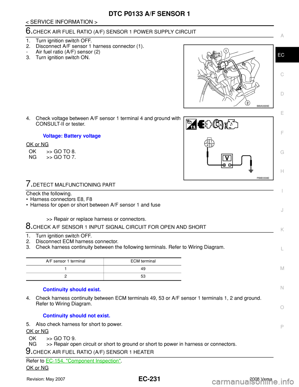
2. Disconnect A/F sensor 1 harness connector (1).
- Air fuel ratio (A/F) sensor (2)
3. Turn ignition switch ON.
4. Check voltage between A/F sensor 1 terminal 4 and ground with
CONSULT-II or tester.
OK or NG
OK >> GO TO 8.
NG >> GO TO 7.
7.DETECT MALFUNCTIONING PART
Check the following.
• Harness connectors E8, F8
• Harness for open or short between A/F sensor 1 and fuse
>> Repair or replace harness or connectors.
8.CHECK A/F SENSOR 1 INPUT SIGNAL CIRCUIT FOR OPEN AND SHORT
1. Turn ignition switch OFF.
2. Disconnect ECM harness connector.
3. Check harness continuity between the following terminals. Refer to Wiring Diagram.
4. Check harness continuity between ECM terminals 49, 53 or A/F sensor 1 terminals 1, 2 and ground.
Refer to Wiring Diagram.
5. Also check harness for short to power.
OK or NG
OK >> GO TO 9.
NG >> Repair open circuit or short to ground or short to power in harness or connectors.
9.CHECK AIR FUEL RATIO (A/F) SENSOR 1 HEATER
Refer to EC-154, "
Component Inspection".
OK or NG
BBIA0699E
Voltage: Battery voltage
PBIB3308E
A/F sensor 1 terminal ECM terminal
149
253
Continuity should exist.
Continuity should not exist.
Page 1310 of 2771
EC-236
< SERVICE INFORMATION >
DTC P0137 HO2S2
Do not use ECM ground terminals when measuring input/output voltage. Doing so may result in dam-
age to the ECM's transistor. Use a ground other than ECM terminals, such as the ground.
: Average voltage for pulse signal (Actual pulse signal can be confirmed by oscilloscope.)
Diagnosis ProcedureINFOID:0000000001702739
1.CHECK GROUND CONNECTIONS
1. Turn ignition switch OFF.
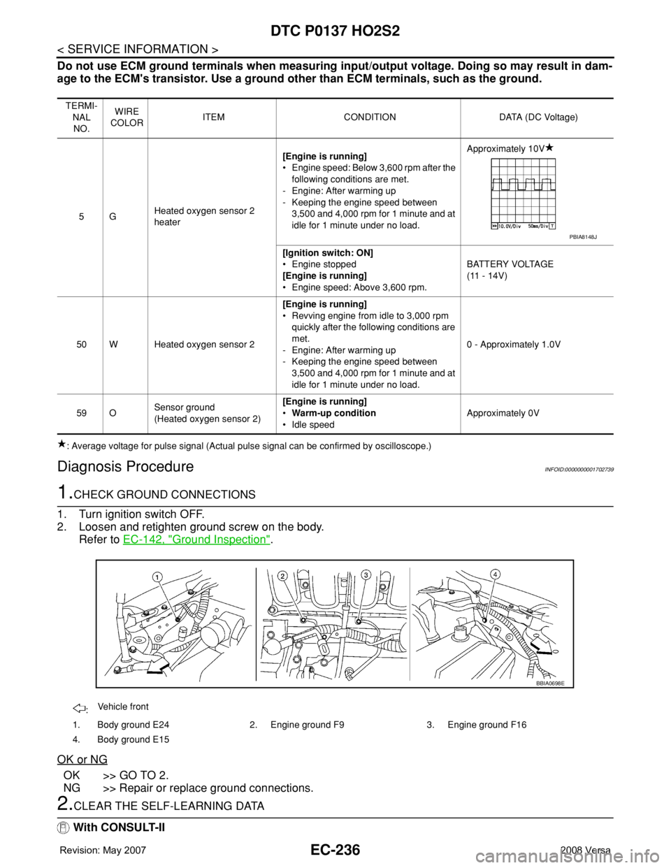
2. Loosen and retighten ground screw on the body.
Refer to EC-142, "
Ground Inspection".
OK or NG
OK >> GO TO 2.
NG >> Repair or replace ground connections.
2.CLEAR THE SELF-LEARNING DATA
With CONSULT-II
TERMI-
NAL
NO.WIRE
COLORITEM CONDITION DATA (DC Voltage)
5GHeated oxygen sensor 2
heater[Engine is running]
• Engine speed: Below 3,600 rpm after the
following conditions are met.
- Engine: After warming up
- Keeping the engine speed between
3,500 and 4,000 rpm for 1 minute and at
idle for 1 minute under no load.Approximately 10V
[Ignition switch: ON]
• Engine stopped
[Engine is running]
• Engine speed: Above 3,600 rpm.BATTERY VOLTAGE
(11 - 14V)
50 W Heated oxygen sensor 2[Engine is running]
• Revving engine from idle to 3,000 rpm
quickly after the following conditions are
met.
- Engine: After warming up
- Keeping the engine speed between
3,500 and 4,000 rpm for 1 minute and at
idle for 1 minute under no load.0 - Approximately 1.0V
59 OSensor ground
(Heated oxygen sensor 2)[Engine is running]
•Warm-up condition
• Idle speedApproximately 0V
PBIA8148J
:Vehicle front
1. Body ground E24 2. Engine ground F9 3. Engine ground F16
4. Body ground E15
BBIA0698E
Page 1318 of 2771
EC-244
< SERVICE INFORMATION >
DTC P0138 HO2S2
Do not use ECM ground terminals when measuring input/output voltage. Doing so may result in dam-
age to the ECM's transistor. Use a ground other than ECM terminals, such as the ground.
: Average voltage for pulse signal (Actual pulse signal can be confirmed by oscilloscope.)
Diagnosis ProcedureINFOID:0000000001702748
PROCEDURE FOR MALFUNCTION A
1.CHECK GROUND CONNECTIONS
1. Turn ignition switch OFF.
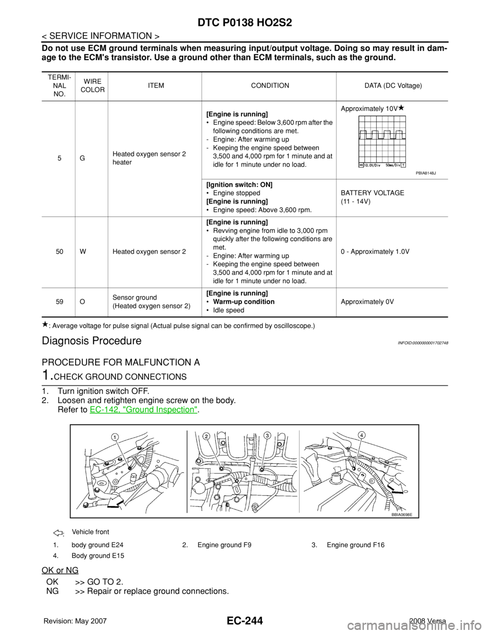
2. Loosen and retighten engine screw on the body.
Refer to EC-142, "
Ground Inspection".
OK or NG
OK >> GO TO 2.
NG >> Repair or replace ground connections.
TERMI-
NAL
NO.WIRE
COLORITEM CONDITION DATA (DC Voltage)
5GHeated oxygen sensor 2
heater[Engine is running]
• Engine speed: Below 3,600 rpm after the
following conditions are met.
- Engine: After warming up
- Keeping the engine speed between
3,500 and 4,000 rpm for 1 minute and at
idle for 1 minute under no load.Approximately 10V
[Ignition switch: ON]
• Engine stopped
[Engine is running]
• Engine speed: Above 3,600 rpm.BATTERY VOLTAGE
(11 - 14V)
50 W Heated oxygen sensor 2[Engine is running]
• Revving engine from idle to 3,000 rpm
quickly after the following conditions are
met.
- Engine: After warming up
- Keeping the engine speed between
3,500 and 4,000 rpm for 1 minute and at
idle for 1 minute under no load.0 - Approximately 1.0V
59 OSensor ground
(Heated oxygen sensor 2)[Engine is running]
•Warm-up condition
• Idle speedApproximately 0V
PBIA8148J
:Vehicle front
1. body ground E24 2. Engine ground F9 3. Engine ground F16
4. Body ground E15
BBIA0698E
Page 1327 of 2771
DTC P0139 HO2S2
EC-253
< SERVICE INFORMATION >
C
D
E
F
G
H
I
J
K
L
MA
EC
N
P O
Do not use ECM ground terminals when measuring input/output voltage. Doing so may result in dam-
age to the ECM's transistor. Use a ground other than ECM terminals, such as the ground.
: Average voltage for pulse signal (Actual pulse signal can be confirmed by oscilloscope.)
Diagnosis ProcedureINFOID:0000000001702757
1.CHECK GROUND CONNECTIONS
1. Turn ignition switch OFF.
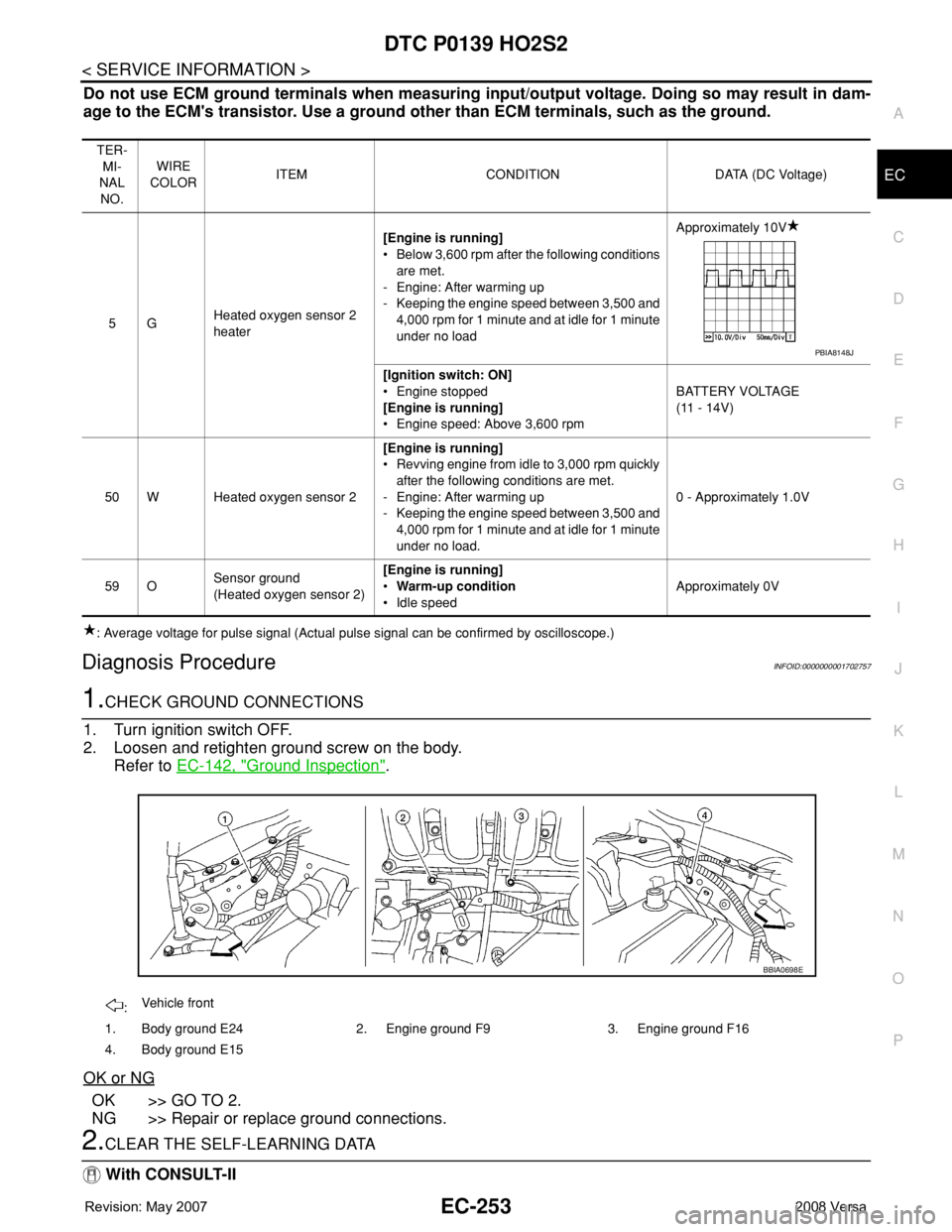
2. Loosen and retighten ground screw on the body.
Refer to EC-142, "
Ground Inspection".
OK or NG
OK >> GO TO 2.
NG >> Repair or replace ground connections.
2.CLEAR THE SELF-LEARNING DATA
With CONSULT-II
TER-
MI-
NAL
NO.WIRE
COLORITEM CONDITION DATA (DC Voltage)
5GHeated oxygen sensor 2
heater[Engine is running]
• Below 3,600 rpm after the following conditions
are met.
- Engine: After warming up
- Keeping the engine speed between 3,500 and
4,000 rpm for 1 minute and at idle for 1 minute
under no loadApproximately 10V
[Ignition switch: ON]
• Engine stopped
[Engine is running]
• Engine speed: Above 3,600 rpmBATTERY VOLTAGE
(11 - 14V)
50 W Heated oxygen sensor 2[Engine is running]
• Revving engine from idle to 3,000 rpm quickly
after the following conditions are met.
- Engine: After warming up
- Keeping the engine speed between 3,500 and
4,000 rpm for 1 minute and at idle for 1 minute
under no load.0 - Approximately 1.0V
59 OSensor ground
(Heated oxygen sensor 2)[Engine is running]
•Warm-up condition
• Idle speedApproximately 0V
PBIA8148J
:Vehicle front
1. Body ground E24 2. Engine ground F9 3. Engine ground F16
4. Body ground E15
BBIA0698E
Page 1334 of 2771
EC-260
< SERVICE INFORMATION >
DTC P0171 FUEL INJECTION SYSTEM FUNCTION
Do not use ECM ground terminals when measuring input/output voltage. Doing so may result in dam-
age to the ECM's transistor. Use a ground other than ECM terminals, such as the ground.
: Average voltage for pulse signal (Actual pulse signal can be confirmed by oscilloscope.)
Diagnosis ProcedureINFOID:0000000001702763
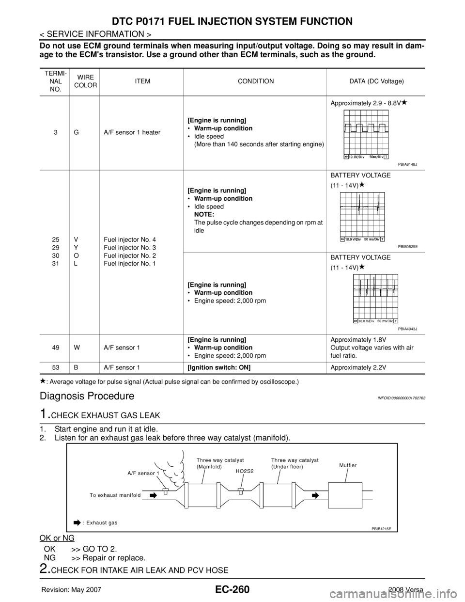
1.CHECK EXHAUST GAS LEAK
1. Start engine and run it at idle.
2. Listen for an exhaust gas leak before three way catalyst (manifold).
OK or NG
OK >> GO TO 2.
NG >> Repair or replace.
2.CHECK FOR INTAKE AIR LEAK AND PCV HOSE
TERMI-
NAL
NO.WIRE
COLORITEM CONDITION DATA (DC Voltage)
3 G A/F sensor 1 heater[Engine is running]
•Warm-up condition
• Idle speed
(More than 140 seconds after starting engine)Approximately 2.9 - 8.8V
25
29
30
31V
Y
O
LFuel injector No. 4
Fuel injector No. 3
Fuel injector No. 2
Fuel injector No. 1[Engine is running]
•Warm-up condition
• Idle speed
NOTE:
The pulse cycle changes depending on rpm at
idleBATTERY VOLTAGE
(11 - 14V)
[Engine is running]
•Warm-up condition
• Engine speed: 2,000 rpmBATTERY VOLTAGE
(11 - 14V)
49 W A/F sensor 1[Engine is running]
•Warm-up condition
• Engine speed: 2,000 rpmApproximately 1.8V
Output voltage varies with air
fuel ratio.
53 B A/F sensor 1[Ignition switch: ON]Approximately 2.2V
PBIA8148J
PBIB0529E
PBIA4943J
PBIB1216E
Page 1341 of 2771
DTC P0172 FUEL INJECTION SYSTEM FUNCTION
EC-267
< SERVICE INFORMATION >
C
D
E
F
G
H
I
J
K
L
MA
EC
N
P O
Do not use ECM ground terminals when measuring input/output voltage. Doing so may result in dam-
age to the ECM's transistor. Use a ground other than ECM terminals, such as the ground.
: Average voltage for pulse signal (Actual pulse signal can be confirmed by oscilloscope.)
Diagnosis ProcedureINFOID:0000000001702767
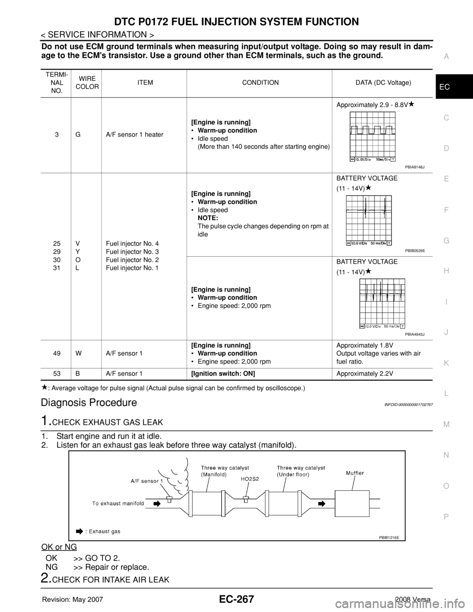
1.CHECK EXHAUST GAS LEAK
1. Start engine and run it at idle.
2. Listen for an exhaust gas leak before three way catalyst (manifold).
OK or NG
OK >> GO TO 2.
NG >> Repair or replace.
2.CHECK FOR INTAKE AIR LEAK
TERMI-
NAL
NO.WIRE
COLORITEM CONDITION DATA (DC Voltage)
3 G A/F sensor 1 heater[Engine is running]
•Warm-up condition
• Idle speed
(More than 140 seconds after starting engine)Approximately 2.9 - 8.8V
25
29
30
31V
Y
O
LFuel injector No. 4
Fuel injector No. 3
Fuel injector No. 2
Fuel injector No. 1[Engine is running]
•Warm-up condition
• Idle speed
NOTE:
The pulse cycle changes depending on rpm at
idleBATTERY VOLTAGE
(11 - 14V)
[Engine is running]
•Warm-up condition
• Engine speed: 2,000 rpmBATTERY VOLTAGE
(11 - 14V)
49 W A/F sensor 1[Engine is running]
•Warm-up condition
• Engine speed: 2,000 rpmApproximately 1.8V
Output voltage varies with air
fuel ratio.
53 B A/F sensor 1[Ignition switch: ON]Approximately 2.2V
PBIA8148J
PBIB0529E
PBIA4943J
PBIB1216E
Page 1363 of 2771
DTC P0300 - P0304 MULTIPLE CYLINDER MISFIRE, NO. 1 - 4 CYLINDER MIS-
FIRE
EC-289
< SERVICE INFORMATION >
C
D
E
F
G
H
I
J
K
L
MA
EC
N
P O
6. Also check harness for short to power.
OK or NG
OK >> GO TO 14.
NG >> Repair open circuit or short to ground or short to power in harness or connectors.
14.CHECK AIR FUEL RATIO (A/F) SENSOR 1 HEATER
Refer to EC-154, "
Component Inspection".
OK or NG
OK >> GO TO 16.
NG >> GO TO 15.
15.REPLACE AIR FUEL RATIO (A/F) SENSOR 1
Replace air fuel ratio (A/F) sensor 1.
CAUTION:
• Discard any A/F sensor which has been dropped from a height of more than 0.5 m (19.7 in) onto a
hard surface such as a concrete floor; use a new one.
• Before installing new A/F sensor, clean exhaust system threads using Oxygen Sensor Thread
Cleaner tool J-43897-18 or J-43897-12 and approved anti-seize lubricant.
>>INSPECTION END
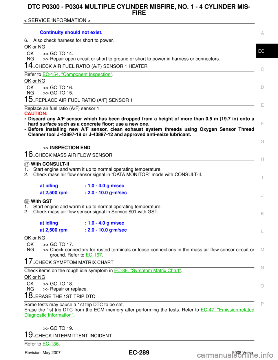
16.CHECK MASS AIR FLOW SENSOR
With CONSULT-II
1. Start engine and warm it up to normal operating temperature.
2. Check mass air flow sensor signal in “DATA MONITOR” mode with CONSULT-II.
With GST
1. Start engine and warm it up to normal operating temperature.
2. Check mass air flow sensor signal in Service $01 with GST.
OK or NG
OK >> GO TO 17.
NG >> Check connectors for rusted terminals or loose connections in the mass air flow sensor circuit or
ground. Refer to EC-167
.
17.CHECK SYMPTOM MATRIX CHART
Check items on the rough idle symptom in EC-88, "
Symptom Matrix Chart".
OK or NG
OK >> GO TO 18.
NG >> Repair or replace.
18.ERASE THE 1ST TRIP DTC
Some tests may cause a 1st trip DTC to be set.
Erase the 1st trip DTC from the ECM memory after performing the tests. Refer to EC-47, "
Emission-related
Diagnostic Information".
>> GO TO 19.
19.CHECK INTERMITTENT INCIDENT
Refer to EC-136
. Continuity should not exist.
at idling : 1.0 - 4.0 g·m/sec
at 2,500 rpm : 2.0 - 10.0 g·m/sec
at idling : 1.0 - 4.0 g·m/sec
at 2,500 rpm : 2.0 - 10.0 g·m/sec
Page 1485 of 2771

DTC P1148 CLOSED LOOP CONTROL
EC-411
< SERVICE INFORMATION >
C
D
E
F
G
H
I
J
K
L
MA
EC
N
P O
DTC P1148 CLOSED LOOP CONTROL
On Board Diagnosis LogicINFOID:0000000001702928
This self-diagnosis has the one trip detection logic.
NOTE:
DTC P1148 is displayed with another DTC for air fuel ratio (A/F) sensor 1.
Perform the trouble diagnosis for the corresponding DTC.
DTC No. Trouble diagnosis name DTC detecting condition Possible cause
P1148
11 4 8Closed loop control
functionThe closed loop control function does not oper-
ate even when vehicle is driving in the specified
condition.• Harness or connectors
[Air fuel ratio (A/F) sensor 1 circuit is open
or shorted.]
• Air fuel ratio (A/F) sensor 1
• Air fuel ratio (A/F) sensor 1 heater