2008 NISSAN LATIO bulb
[x] Cancel search: bulbPage 2138 of 2771

LT-1
ELECTRICAL
C
D
E
F
G
H
I
J
L
M
SECTION LT
A
B
LT
N
O
P
CONTENTS
LIGHTING SYSTEM
SERVICE INFORMATION ............................3
PRECAUTIONS ...................................................3
Precaution for Supplemental Restraint System
(SRS) "AIR BAG" and "SEAT BELT PRE-TEN-
SIONER" ...................................................................
3
HEADLAMP (FOR USA) .....................................4
Component Parts and Harness Connector Loca-
tion ............................................................................
4
System Description ...................................................4
CAN COMMUNICATION SYSTEM DESCRIP-
TION ..........................................................................
5
Schematic .................................................................6
Wiring Diagram .........................................................7
Terminal and Reference Value for BCM .................10
Terminal and Reference Value for IPDM E/R .........10
How to Perform Trouble Diagnosis .........................11
Preliminary Check ...................................................11
CONSULT-III Function (BCM) .................................11
CONSULT-III Function (IPDM E/R) .........................12
Headlamp High Beam Does Not Illuminate (Both
Sides) ......................................................................
13
Headlamp High Beam Does Not Illuminate (One
Side) ........................................................................
15
High Beam Indicator Lamp Does Not Illuminate .....16
Headlamp Low Beam Does Not Illuminate (Both
Sides) ......................................................................
16
Headlamp Low Beam Does Not Illuminate (One
Side) ........................................................................
19
Headlamps Do Not Turn OFF .................................20
Aiming Adjustment ..................................................21
Bulb Replacement ...................................................22
Removal and Installation .........................................23
Disassembly and Assembly ....................................23
HEADLAMP (FOR CANADA) - DAYTIME
LIGHT SYSTEM - ...............................................
25
Component Parts and Harness Connector Loca-
tion ..........................................................................
25
System Description .................................................25
CAN Communication System Description ...............27
Schematic ................................................................28
Wiring Diagram - DTRL - .........................................29
Terminal and Reference Value for BCM ..................32
Terminal and Reference Value for IPDM E/R ..........32
How to Perform Trouble Diagnosis ..........................33
Preliminary Check ...................................................33
CONSULT-III Function (BCM) .................................33
CONSULT-III Function (IPDM E/R) .........................33
Daytime Light Control Does Not Operate Properly
(High Beam Headlamps Operate Properly) .............
33
Aiming Adjustment ...................................................35
Bulb Replacement ...................................................36
Removal and Installation .........................................37
Disassembly and Assembly .....................................37
FRONT FOG LAMP ..........................................39
Component Parts and Harness Connector Loca-
tion ...........................................................................
39
System Description ..................................................39
CAN Communication System Description ...............40
Wiring Diagram - F/FOG - .......................................41
Terminal and Reference Value for BCM ..................42
Terminal and Reference Value for IPDM E/R ..........42
How to Proceed with Trouble Diagnosis ..................43
Preliminary Check ...................................................43
CONSULT-III Function (BCM) .................................43
CONSULT-III Function (IPDM E/R) .........................43
Front Fog lamps Do Not Illuminate (Both Sides) .....43
Front Fog Lamp Does Not Illuminate (One Side) ....45
Aiming Adjustment ...................................................46
Bulb Replacement ...................................................47
Removal and Installation .........................................47
TURN SIGNAL AND HAZARD WARNING
LAMPS ..............................................................
48
Component Parts and Harness Connector Loca-
tion ...........................................................................
48
System Description ..................................................48
CAN Communication System Description ...............50
Schematic ................................................................51
Page 2139 of 2771

LT-2
Wiring Diagram - TURN - ........................................52
Terminal and Reference Value for BCM .................55
How to Proceed with Trouble Diagnosis .................55
Preliminary Check ..................................................56
CONSULT-III Function (BCM) ................................56
Turn Signals Do Not Operate .................................56
Front Turn Signal Lamp Does Not Operate ............56
Rear Turn Signal Lamp Does Not Operate ............57
Hazard Warning Lamp Does Not Operate But
Turn Signal Lamp Operates ...................................
58
Turn Signal Indicator Lamp Does Not Operate ......59
Bulb Replacement for Front Turn Signal Lamp ......59
Bulb Replacement for Rear Turn Signal Lamp .......59
Removal and Installation of Front Turn Signal
Lamp .......................................................................
59
Removal and Installation of Rear Turn Signal
Lamp .......................................................................
59
LIGHTING AND TURN SIGNAL SWITCH .........60
Removal and Installation ........................................60
HAZARD SWITCH .............................................61
Removal and Installation ........................................61
COMBINATION SWITCH ..................................62
Wiring Diagram - COMBSW - .................................62
Combination Switch Reading Function ...................62
Terminal and Reference Value for BCM .................63
CONSULT-III Function (BCM) ................................63
Combination Switch Inspection ..............................63
Removal and Installation ........................................65
STOP LAMP ......................................................66
Wiring Diagram - STOP/L .......................................66
Wiring Diagram - STOP/L .......................................67
Bulb Replacement for High-Mounted Stop Lamp ...67
Bulb Replacement for Rear Combination Lamp for
Stop Lamp ..............................................................
68
Removal and Installation of High-Mounted Stop
Lamp .......................................................................
68
Removal and Installation of Rear Combination
Lamp for Stop Lamp ...............................................
69
BACK-UP LAMP ................................................70
Wiring Diagram - BACK/L - .....................................70
Bulb Replacement ..................................................70
Removal and Installation ........................................71
PARKING, LICENSE PLATE AND TAIL
LAMPS ...............................................................
72
Component Parts and Harness Connector Loca-
tion ..........................................................................
72
System Description .................................................72
CAN Communication System Description ..............73
Schematic ...............................................................74
Wiring Diagram - TAIL/L - .......................................75
Terminal and Reference Value for BCM .................78
Terminal and Reference Value for IPDM E/R .........78
How to Proceed with Trouble Diagnosis .................79
Preliminary Check ...................................................79
CONSULT-III Function (BCM) ................................79
CONSULT-III Function (IPDM E/R) ........................79
Parking, License Plate and Tail Lamps Do Not Il-
luminate ..................................................................
79
Parking, License Plate and Tail Lamps Do Not
Turn OFF (After Approx. 10 Minutes) .....................
82
Bulb Replacement ...................................................82
Removal and Installation .........................................83
REAR COMBINATION LAMP ...........................85
Component .............................................................85
Bulb Replacement ...................................................85
Removal and Installation .........................................86
Disassembly and Assembly ....................................86
INTERIOR LAMP ...............................................87
Map Lamp ...............................................................87
Luggage Compartment Lamp .................................87
INTERIOR ROOM LAMP ...................................89
Component Parts and Harness Connector Loca-
tion ..........................................................................
89
System Description .................................................89
Schematic ...............................................................93
Wiring Diagram - INT/L - .........................................94
Terminal and Reference Value for BCM .................98
How to Proceed with Trouble Diagnosis .................98
Preliminary Check ...................................................99
CONSULT-III Function (BCM) ................................99
Interior Room Lamp Control Does Not Operate
(With Map Lamp) ..................................................
100
Interior Room Lamp Control Does Not Operate
(Without Map Lamp) .............................................
102
Bulb Replacement .................................................103
Removal and Installation .......................................103
ILLUMINATION ................................................105
System Description ...............................................105
CAN Communication System Description ............106
Schematic .............................................................107
Wiring Diagram - ILL - ...........................................108
Bulb Replacement .................................................111
BULB SPECIFICATIONS .................................113
Headlamp ..............................................................113
Exterior Lamp ........................................................113
Interior Lamp/Illumination ......................................113
Page 2151 of 2771
LT-14
< SERVICE INFORMATION >
HEADLAMP (FOR USA)
OK or NG
OK >> GO TO 3.
NG >> GO TO 4.
3.CHECK IPDM E/R
1. Select “IPDM E/R” on CONSULT-III. Select “DATA MONITOR” on “SELECT DIAG MODE” screen.
2. Make sure “HL HI REQ” turns ON when lighting switch is in high position.
OK or NG
OK >> Replace IPDM E/R. Refer to PG-26, "Removal and Installation of IPDM E/R" .
NG >> Replace BCM. Refer to BCS-18, "
Removal and Installation of BCM" .
4.HEADLAMP HIGH BEAM FUSE INSPECTION
Inspect 10A fuse No. 34 (LH) and fuse No. 35 (RH).
OK or NG
OK >> GO TO 5.
NG >> Repair harness.
5.BULB INSPECTION
Inspect inoperative headlamp bulbs.
OK or NG
OK >> GO TO 6.
NG >> Replace headlamp bulb. LT-22, "
Bulb Replacement" .
6.CHECK HEADLAMP INPUT SIGNAL
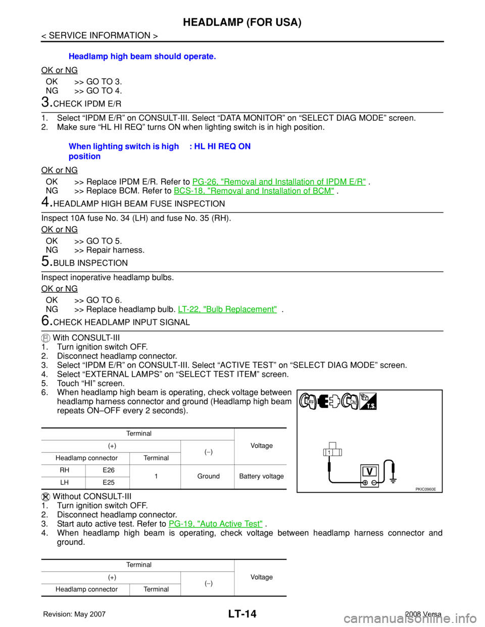
With CONSULT-III
1. Turn ignition switch OFF.
2. Disconnect headlamp connector.
3. Select “IPDM E/R” on CONSULT-III. Select “ACTIVE TEST” on “SELECT DIAG MODE” screen.
4. Select “EXTERNAL LAMPS” on “SELECT TEST ITEM” screen.
5. Touch “HI” screen.
6. When headlamp high beam is operating, check voltage between
headlamp harness connector and ground (Headlamp high beam
repeats ON–OFF every 2 seconds).
Without CONSULT-III
1. Turn ignition switch OFF.
2. Disconnect headlamp connector.
3. Start auto active test. Refer to PG-19, "
Auto Active Test" .
4. When headlamp high beam is operating, check voltage between headlamp harness connector and
ground.Headlamp high beam should operate.
When lighting switch is high
position: HL HI REQ ON
Te r m i n a l
Vo l ta g e (+)
(−)
Headlamp connector Terminal
RH E26
1 Ground Battery voltage
LH E25
Te r m i n a l
Vo l ta g e (+)
(−)
Headlamp connector Terminal
PKIC0960E
Page 2152 of 2771
HEADLAMP (FOR USA)
LT-15
< SERVICE INFORMATION >
C
D
E
F
G
H
I
J
L
MA
B
LT
N
O
P
OK or NG
OK >> GO TO 7.
NG >> GO TO 8.
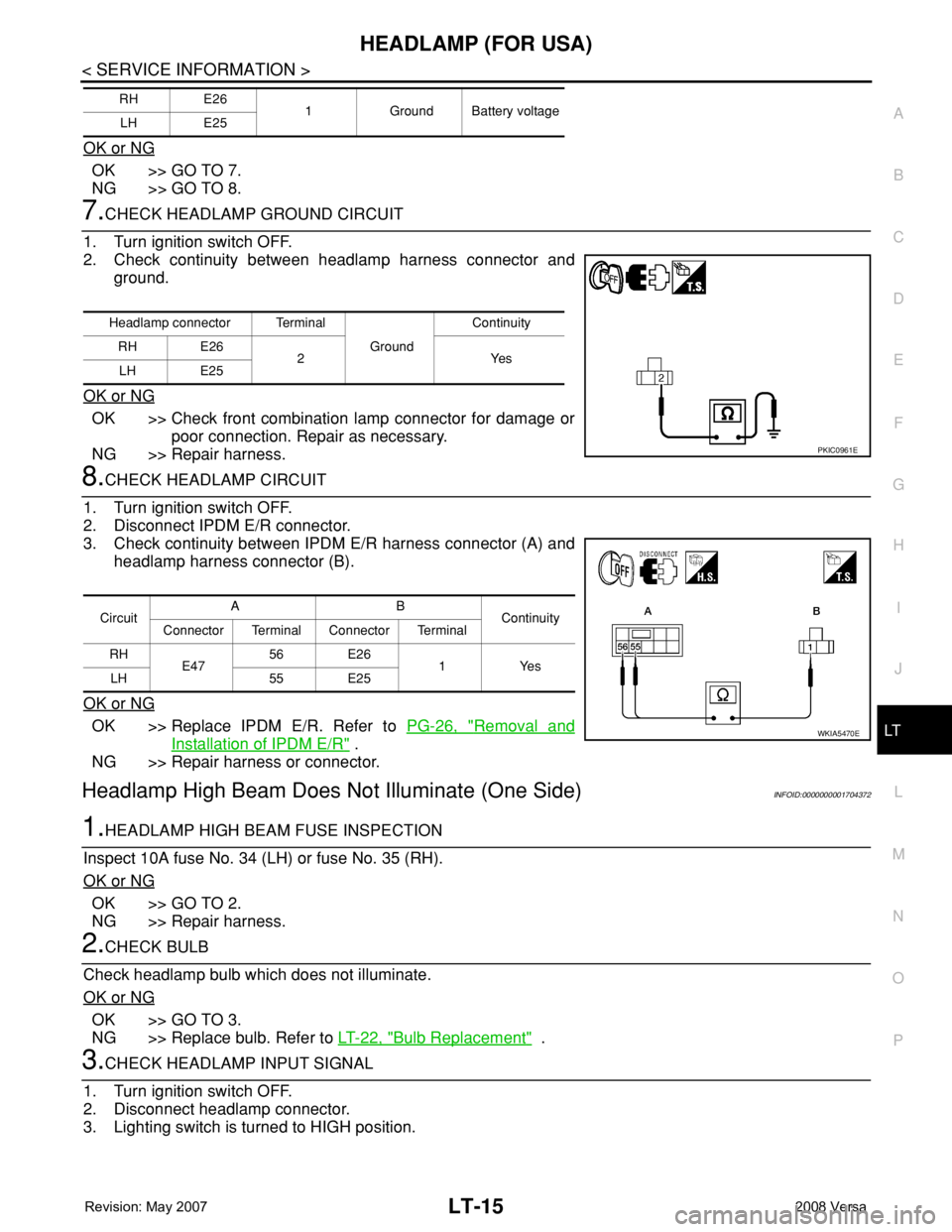
7.CHECK HEADLAMP GROUND CIRCUIT
1. Turn ignition switch OFF.
2. Check continuity between headlamp harness connector and
ground.
OK or NG
OK >> Check front combination lamp connector for damage or
poor connection. Repair as necessary.
NG >> Repair harness.
8.CHECK HEADLAMP CIRCUIT
1. Turn ignition switch OFF.
2. Disconnect IPDM E/R connector.
3. Check continuity between IPDM E/R harness connector (A) and
headlamp harness connector (B).
OK or NG
OK >> Replace IPDM E/R. Refer to PG-26, "Removal and
Installation of IPDM E/R" .
NG >> Repair harness or connector.
Headlamp High Beam Does Not Illuminate (One Side)INFOID:0000000001704372
1.HEADLAMP HIGH BEAM FUSE INSPECTION
Inspect 10A fuse No. 34 (LH) or fuse No. 35 (RH).
OK or NG
OK >> GO TO 2.
NG >> Repair harness.
2.CHECK BULB
Check headlamp bulb which does not illuminate.
OK or NG
OK >> GO TO 3.
NG >> Replace bulb. Refer to LT-22, "
Bulb Replacement" .
3.CHECK HEADLAMP INPUT SIGNAL
1. Turn ignition switch OFF.
2. Disconnect headlamp connector.
3. Lighting switch is turned to HIGH position.
RH E26
1 Ground Battery voltage
LH E25
Headlamp connector Terminal
Ground Continuity
RH E26
2Yes
LH E25
PKIC0961E
CircuitAB
Continuity
Connector Terminal Connector Terminal
RH
E4756 E26
1 Yes
LH 55 E25
WKIA5470E
Page 2153 of 2771
LT-16
< SERVICE INFORMATION >
HEADLAMP (FOR USA)
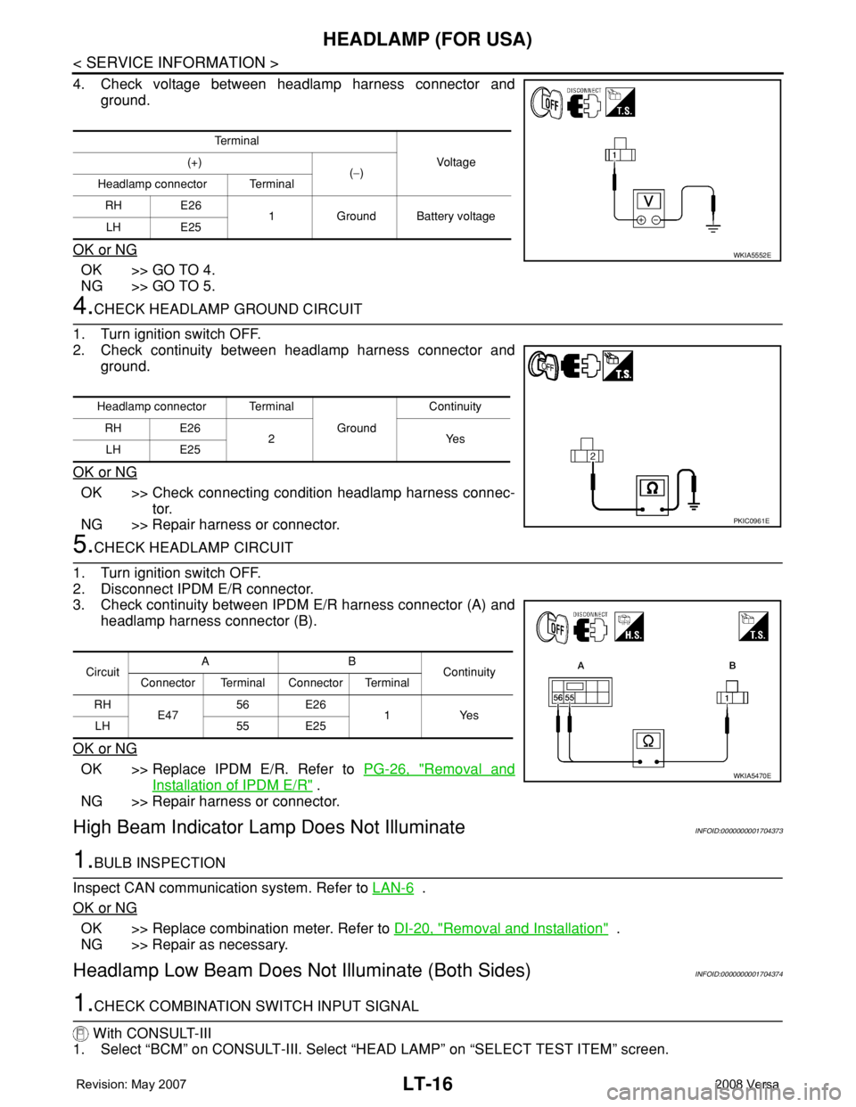
4. Check voltage between headlamp harness connector and
ground.
OK or NG
OK >> GO TO 4.
NG >> GO TO 5.
4.CHECK HEADLAMP GROUND CIRCUIT
1. Turn ignition switch OFF.
2. Check continuity between headlamp harness connector and
ground.
OK or NG
OK >> Check connecting condition headlamp harness connec-
tor.
NG >> Repair harness or connector.
5.CHECK HEADLAMP CIRCUIT
1. Turn ignition switch OFF.
2. Disconnect IPDM E/R connector.
3. Check continuity between IPDM E/R harness connector (A) and
headlamp harness connector (B).
OK or NG
OK >> Replace IPDM E/R. Refer to PG-26, "Removal and
Installation of IPDM E/R" .
NG >> Repair harness or connector.
High Beam Indicator Lamp Does Not IlluminateINFOID:0000000001704373
1.BULB INSPECTION
Inspect CAN communication system. Refer to LAN-6
.
OK or NG
OK >> Replace combination meter. Refer to DI-20, "Removal and Installation" .
NG >> Repair as necessary.
Headlamp Low Beam Does Not Illuminate (Both Sides)INFOID:0000000001704374
1.CHECK COMBINATION SWITCH INPUT SIGNAL
With CONSULT-III
1. Select “BCM” on CONSULT-III. Select “HEAD LAMP” on “SELECT TEST ITEM” screen.
Te r m i n a l
Voltag e (+)
(−)
Headlamp connector Terminal
RH E26
1 Ground Battery voltage
LH E25
WKIA5552E
Headlamp connector Terminal
Ground Continuity
RH E26
2Yes
LH E25
PKIC0961E
CircuitAB
Continuity
Connector Terminal Connector Terminal
RH
E47 56 E26
1Yes
LH 55 E25
WKIA5470E
Page 2154 of 2771
HEADLAMP (FOR USA)
LT-17
< SERVICE INFORMATION >
C
D
E
F
G
H
I
J
L
MA
B
LT
N
O
P
2. Select “DATA MONITOR” on “SELECT DIAG MODE” screen. Make sure that “HEAD LAMP SW 1” and
“HEAD LAMP SW 2” turns ON-OFF linked with operation of lighting switch.
Without CONSULT-III
Refer to LT-63, "
Combination Switch Inspection" .
OK or NG
OK >> GO TO 2.
NG >> Check combination switch (lighting switch). Refer to LT-63, "
Combination Switch Inspection" .
2.CHECK HEADLAMP ACTIVE TEST
With CONSULT-III
1. Select “IPDM E/R” on CONSULT-III. Select “ACTIVE TEST” on “SELECT DIAG MODE” screen.
2. Select “EXTERNAL LAMPS” on “SELECT TEST ITEM” screen.
3. Touch “LO” screen.
4. Make sure headlamp low beam operates.
Without CONSULT-III
1. Start auto active test. Refer to PG-19, "
Auto Active Test" .
2. Make sure headlamp low beam operates.
OK or NG
OK >> GO TO 3.
NG >> GO TO 4.
3.CHECK IPDM E/R
1. Select “IPDM E/R” on CONSULT-III. Select “DATA MONITOR” on “SELECT DIAG MODE” screen.
2. Make sure “HL LO REQ” turns ON when lighting switch is in 2ND position.
OK or NG
OK >> Replace IPDM E/R. Refer to PG-26, "Removal and Installation of IPDM E/R" .
NG >> Replace BCM. Refer toBCS-18, "
Removal and Installation of BCM" .
4.HEADLAMP LOW BEAM FUSE INSPECTION
Inspect 15A fuse No. 40 (LH) and fuse No. 41 (RH).
OK or NG
OK >> GO TO 5.
NG >> Repair harness.
5.BULB INSPECTION
Inspect inoperative headlamp bulbs.
OK or NG
OK >> GO TO 6.
NG >> Replace headlamp bulb.LT-22, "
Bulb Replacement" .
6.CHECK HEADLAMP INPUT SIGNAL
With CONSULT-III
1. Turn ignition switch OFF.
2. Disconnect headlamp connector.
3. Select “IPDM E/R” on CONSULT-III. Select “ACTIVE TEST” on “SELECT DIAG MODE” screen.
4. Select “EXTERNAL LAMPS” on “SELECT TEST ITEM” screen. When lighting switch is 2ND
position: HEAD LAMP SW 1 ON
: HEAD LAMP SW 2 ON
Headlamp low beam should operate.
Headlamp low beam should operate.
When lighting switch is 2ND
position: HL LO REQ ON
Page 2156 of 2771
HEADLAMP (FOR USA)
LT-19
< SERVICE INFORMATION >
C
D
E
F
G
H
I
J
L
MA
B
LT
N
O
P
Headlamp Low Beam Does Not Illuminate (One Side)INFOID:0000000001704375
1.HEADLAMP LOW BEAM FUSE INSPECTION
Inspect 15A fuse No. 40 (LH) and fuse No. 41 (RH).
OK or NG
OK >> GO TO 2.
NG >> Repair harness.
2.CHECK BULB
Check bulb of headlamp which does not illuminate.
OK or NG
OK >> GO TO 3.
NG >> Replace bulb. Refer to LT-22, "
Bulb Replacement" .
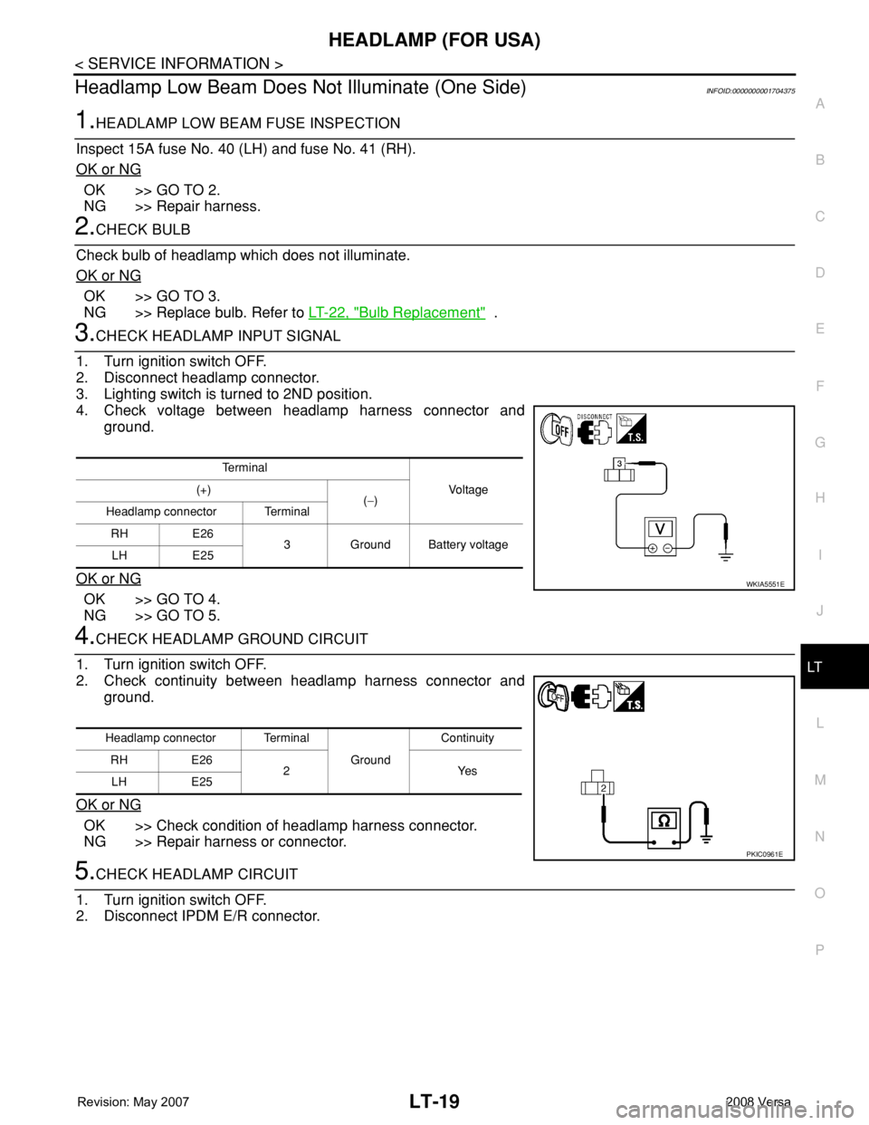
3.CHECK HEADLAMP INPUT SIGNAL
1. Turn ignition switch OFF.
2. Disconnect headlamp connector.
3. Lighting switch is turned to 2ND position.
4. Check voltage between headlamp harness connector and
ground.
OK or NG
OK >> GO TO 4.
NG >> GO TO 5.
4.CHECK HEADLAMP GROUND CIRCUIT
1. Turn ignition switch OFF.
2. Check continuity between headlamp harness connector and
ground.
OK or NG
OK >> Check condition of headlamp harness connector.
NG >> Repair harness or connector.
5.CHECK HEADLAMP CIRCUIT
1. Turn ignition switch OFF.
2. Disconnect IPDM E/R connector.
Te r m i n a l
Vo l ta g e (+)
(−)
Headlamp connector Terminal
RH E26
3 Ground Battery voltage
LH E25
WKIA5551E
Headlamp connector Terminal
Ground Continuity
RH E26
2Yes
LH E25
PKIC0961E
Page 2159 of 2771
LT-22
< SERVICE INFORMATION >
HEADLAMP (FOR USA)
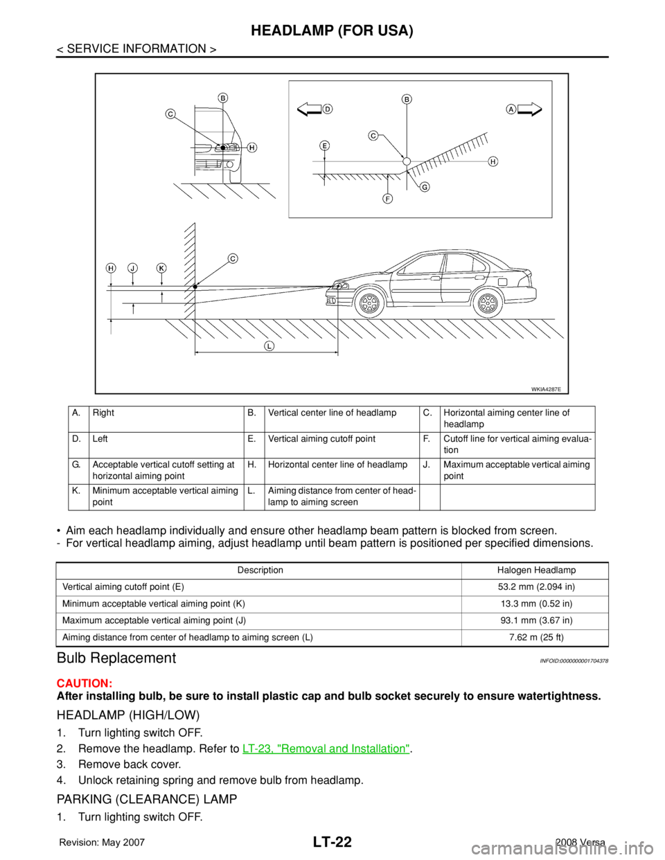
• Aim each headlamp individually and ensure other headlamp beam pattern is blocked from screen.
- For vertical headlamp aiming, adjust headlamp until beam pattern is positioned per specified dimensions.
Bulb ReplacementINFOID:0000000001704378
CAUTION:
After installing bulb, be sure to install plastic cap and bulb socket securely to ensure watertightness.
HEADLAMP (HIGH/LOW)
1. Turn lighting switch OFF.
2. Remove the headlamp. Refer to LT-23, "
Removal and Installation".
3. Remove back cover.
4. Unlock retaining spring and remove bulb from headlamp.
PARKING (CLEARANCE) LAMP
1. Turn lighting switch OFF.
A. Right B. Vertical center line of headlamp C. Horizontal aiming center line of
headlamp
D. Left E. Vertical aiming cutoff point F. Cutoff line for vertical aiming evalua-
tion
G. Acceptable vertical cutoff setting at
horizontal aiming pointH. Horizontal center line of headlamp J. Maximum acceptable vertical aiming
point
K. Minimum acceptable vertical aiming
pointL. Aiming distance from center of head-
lamp to aiming screen
WKIA4287E
Description Halogen Headlamp
Vertical aiming cutoff point (E)53.2 mm (2.094 in)
Minimum acceptable vertical aiming point (K) 13.3 mm (0.52 in)
Maximum acceptable vertical aiming point (J) 93.1 mm (3.67 in)
Aiming distance from center of headlamp to aiming screen (L) 7.62 m (25 ft)