Page 559 of 2771
INTELLIGENT KEY SYSTEM
BL-125
< SERVICE INFORMATION >
C
D
E
F
G
H
J
K
L
MA
B
BL
N
O
P
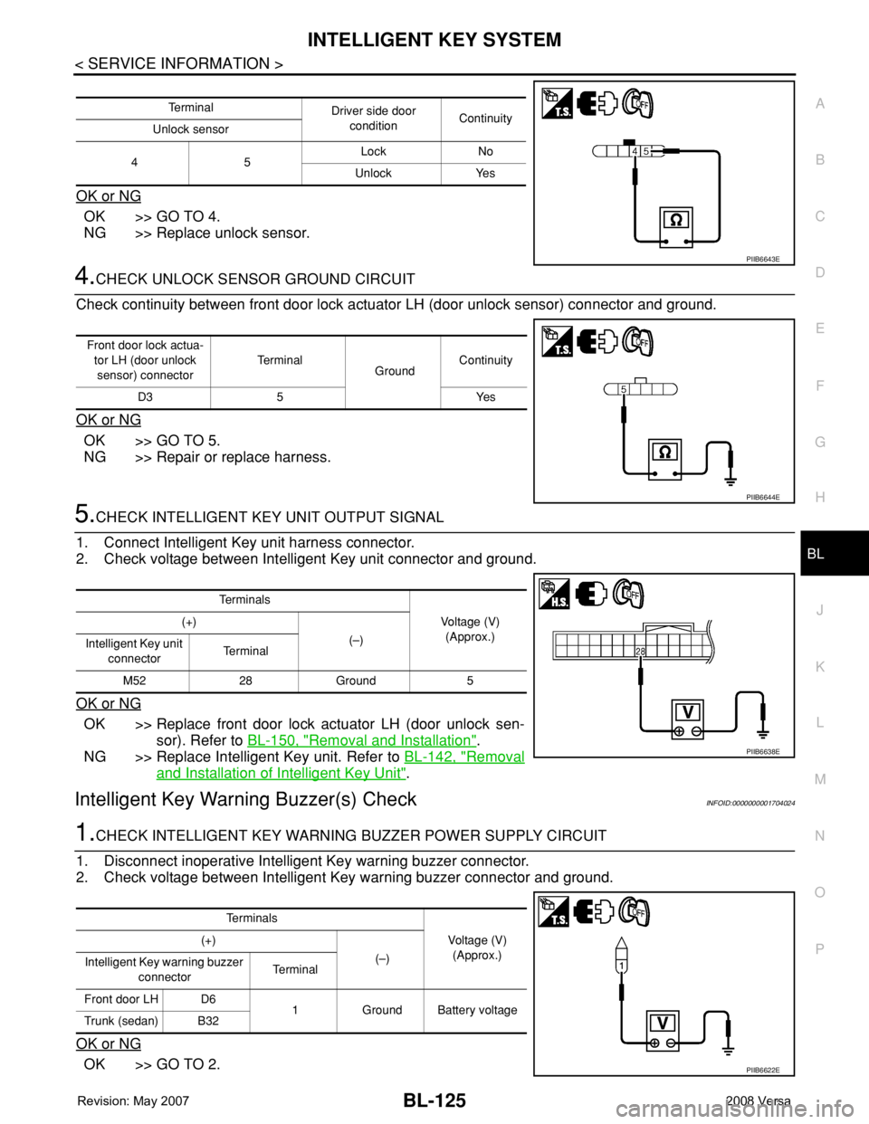
OK or NG
OK >> GO TO 4.
NG >> Replace unlock sensor.
4.CHECK UNLOCK SENSOR GROUND CIRCUIT
Check continuity between front door lock actuator LH (door unlock sensor) connector and ground.
OK or NG
OK >> GO TO 5.
NG >> Repair or replace harness.
5.CHECK INTELLIGENT KEY UNIT OUTPUT SIGNAL
1. Connect Intelligent Key unit harness connector.
2. Check voltage between Intelligent Key unit connector and ground.
OK or NG
OK >> Replace front door lock actuator LH (door unlock sen-
sor). Refer to BL-150, "
Removal and Installation".
NG >> Replace Intelligent Key unit. Refer to BL-142, "
Removal
and Installation of Intelligent Key Unit".
Intelligent Key Warning Buzzer(s) CheckINFOID:0000000001704024
1.CHECK INTELLIGENT KEY WARNING BUZZER POWER SUPPLY CIRCUIT
1. Disconnect inoperative Intelligent Key warning buzzer connector.
2. Check voltage between Intelligent Key warning buzzer connector and ground.
OK or NG
OK >> GO TO 2.
Te r m i n a l
Driver side door
conditionContinuity
Unlock sensor
45Lock No
Unlock Yes
PIIB6643E
Front door lock actua-
tor LH (door unlock
sensor) connectorTe r m i n a l
GroundContinuity
D3 5 Yes
PIIB6644E
Te r m i n a l s
Voltage (V)
(Approx.) (+)
(–)
Intelligent Key unit
connectorTe r m i n a l
M52 28 Ground 5
PIIB6638E
Te r m i n a l s
Voltage (V)
(Approx.) (+)
(–)
Intelligent Key warning buzzer
connectorTerminal
Front door LH D6
1 Ground Battery voltage
Trunk (sedan) B32
PIIB6622E
Page 560 of 2771
BL-126
< SERVICE INFORMATION >
INTELLIGENT KEY SYSTEM
NG >> Repair or replace Intelligent Key warning buzzer power supply circuit.
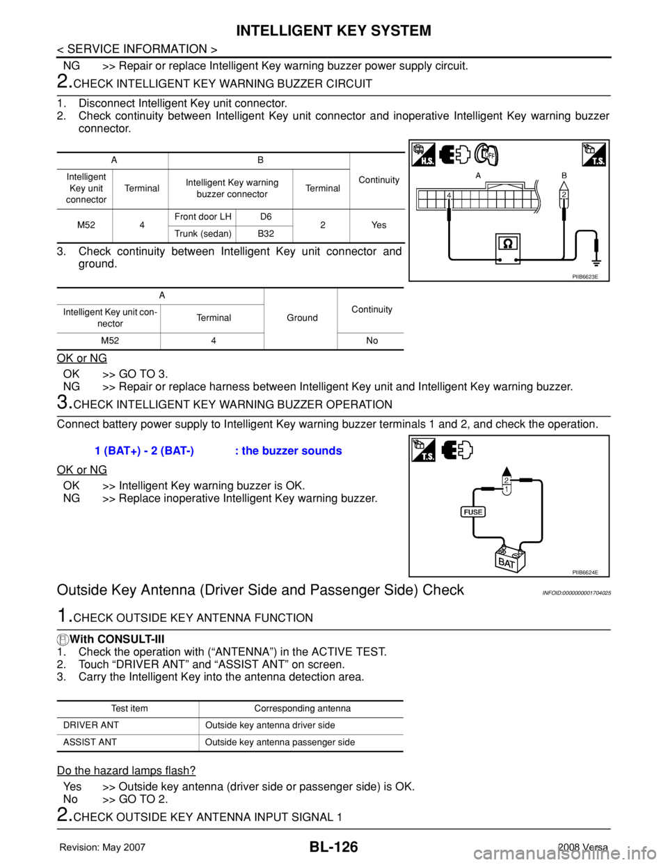
2.CHECK INTELLIGENT KEY WARNING BUZZER CIRCUIT
1. Disconnect Intelligent Key unit connector.
2. Check continuity between Intelligent Key unit connector and inoperative Intelligent Key warning buzzer
connector.
3. Check continuity between Intelligent Key unit connector and
ground.
OK or NG
OK >> GO TO 3.
NG >> Repair or replace harness between Intelligent Key unit and Intelligent Key warning buzzer.
3.CHECK INTELLIGENT KEY WARNING BUZZER OPERATION
Connect battery power supply to Intelligent Key warning buzzer terminals 1 and 2, and check the operation.
OK or NG
OK >> Intelligent Key warning buzzer is OK.
NG >> Replace inoperative Intelligent Key warning buzzer.
Outside Key Antenna (Driver Side and Passenger Side) CheckINFOID:0000000001704025
1.CHECK OUTSIDE KEY ANTENNA FUNCTION
With CONSULT-III
1. Check the operation with (“ANTENNA”) in the ACTIVE TEST.
2. Touch “DRIVER ANT” and “ASSIST ANT” on screen.
3. Carry the Intelligent Key into the antenna detection area.
Do the hazard lamps flash?
Yes >> Outside key antenna (driver side or passenger side) is OK.
No >> GO TO 2.
2.CHECK OUTSIDE KEY ANTENNA INPUT SIGNAL 1
AB
Continuity Intelligent
Key unit
connectorTe r m i n a lIntelligent Key warning
buzzer connectorTe r m i n a l
M52 4Front door LH D6
2Yes
Trunk (sedan) B32
A
GroundContinuity
Intelligent Key unit con-
nectorTerminal
M52 4 No
PIIB6623E
1 (BAT+) - 2 (BAT-) : the buzzer sounds
PIIB6624E
Test item Corresponding antenna
DRIVER ANT Outside key antenna driver side
ASSIST ANT Outside key antenna passenger side
Page 561 of 2771
INTELLIGENT KEY SYSTEM
BL-127
< SERVICE INFORMATION >
C
D
E
F
G
H
J
K
L
MA
B
BL
N
O
P
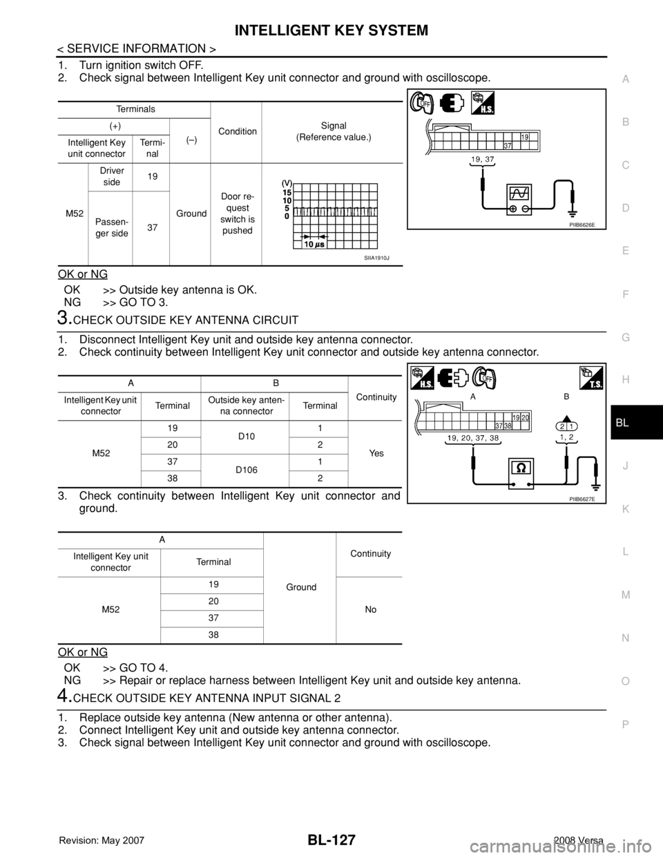
1. Turn ignition switch OFF.
2. Check signal between Intelligent Key unit connector and ground with oscilloscope.
OK or NG
OK >> Outside key antenna is OK.
NG >> GO TO 3.
3.CHECK OUTSIDE KEY ANTENNA CIRCUIT
1. Disconnect Intelligent Key unit and outside key antenna connector.
2. Check continuity between Intelligent Key unit connector and outside key antenna connector.
3. Check continuity between Intelligent Key unit connector and
ground.
OK or NG
OK >> GO TO 4.
NG >> Repair or replace harness between Intelligent Key unit and outside key antenna.
4.CHECK OUTSIDE KEY ANTENNA INPUT SIGNAL 2
1. Replace outside key antenna (New antenna or other antenna).
2. Connect Intelligent Key unit and outside key antenna connector.
3. Check signal between Intelligent Key unit connector and ground with oscilloscope.
Te r m i n a l s
ConditionSignal
(Reference value.) (+)
(–)
Intelligent Key
unit connectorTe r m i -
nal
M52Driver
side19
GroundDoor re-
quest
switch is
pushed Passen-
ger side37
PIIB6626E
SIIA1910J
AB
Continuity
Intelligent Key unit
connectorTe r m i n a lOutside key anten-
na connectorTe r m i n a l
M5219
D101
Ye s 20 2
37
D1061
38 2
A
GroundContinuity
Intelligent Key unit
connectorTe r m i n a l
M5219
No 20
37
38
PIIB6627E
Page 562 of 2771
BL-128
< SERVICE INFORMATION >
INTELLIGENT KEY SYSTEM
OK or NG
OK >> Replace malfunctioning outside key antenna.
NG >> Replace Intelligent Key unit. Refer to BL-142, "
Removal and Installation of Intelligent Key Unit".
Outside Key Antenna (Rear Bumper) CheckINFOID:0000000001704026
1.CHECK REAR BUMPER ANTENNA FUNCTION
With CONSULT-III
1. Check the operation with (“ANTENNA”) in the ACTIVE TEST.
2. Touch “BD/TR ANT” on screen.
3. Carry the Intelligent Key into the antenna detection area.
Do the hazard lamps flash?
Yes >> Rear bumper antenna is OK.
No >> GO TO 2.
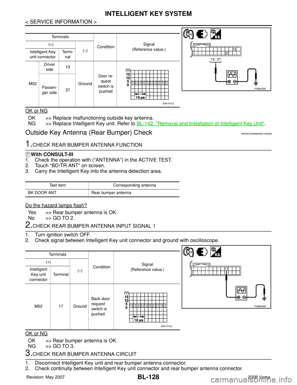
2.CHECK REAR BUMPER ANTENNA INPUT SIGNAL 1
1. Turn ignition switch OFF.
2. Check signal between Intelligent Key unit connector and ground with oscilloscope.
OK or NG
OK >> Rear bumper antenna is OK.
NG >> GO TO 3.
3.CHECK REAR BUMPER ANTENNA CIRCUIT
1. Disconnect Intelligent Key unit and rear bumper antenna connector.
2. Check continuity between Intelligent Key unit connector and rear bumper antenna connector.
Te r m i n a l s
ConditionSignal
(Reference value.) (+)
(–)
Intelligent Key
unit connectorTe r m i -
nal
M52Driver
side19
GroundDoor re-
quest
switch is
pushed Passen-
ger side37
PIIB6626E
SIIA1910J
Test item Corresponding antenna
BK DOOR ANT Rear bumper antenna
Te r m i n a l s
ConditionSignal
(Reference value.) (+)
(–) Intelligent
Key unit
connectorTe r m i n a l
M52 17 GroundBack door
request
switch is
pushed
PIIB6628E
SIIA1910J
Page 563 of 2771
INTELLIGENT KEY SYSTEM
BL-129
< SERVICE INFORMATION >
C
D
E
F
G
H
J
K
L
MA
B
BL
N
O
P
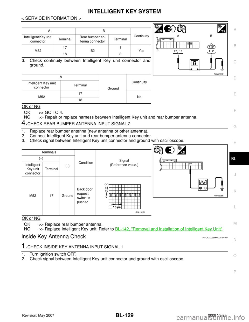
3. Check continuity between Intelligent Key unit connector and
ground.
OK or NG
OK >> GO TO 4.
NG >> Repair or replace harness between Intelligent Key unit and rear bumper antenna.
4.CHECK REAR BUMPER ANTENNA INPUT SIGNAL 2
1. Replace rear bumper antenna (new antenna or other antenna).
2. Connect Intelligent Key unit and rear bumper antenna connector.
3. Check signal between Intelligent Key unit connector and ground with oscilloscope.
OK or NG
OK >> Replace rear bumper antenna.
NG >> Replace Intelligent Key unit. Refer to BL-142, "
Removal and Installation of Intelligent Key Unit".
Inside Key Antenna CheckINFOID:0000000001704027
1.CHECK INSIDE KEY ANTENNA INPUT SIGNAL 1
1. Turn ignition switch OFF.
2. Check signal between Intelligent Key unit connector and ground with oscilloscope.
AB
Continuity
Intelligent Key unit
connectorTe r m i n a lRear bumper an-
tenna connectorTe r m i n a l
M5217
B21
Ye s
18 2
A
GroundContinuity
Intelligent Key unit
connectorTe r m i n a l
M5217
No
18
PIIB6629E
Te r m i n a l s
ConditionSignal
(Reference value.) (+)
(–) Intelligent
Key unit
connectorTe r m i n a l
M52 17 GroundBack door
request
switch is
pushed
PIIB6628E
SIIA1910J
Page 564 of 2771
BL-130
< SERVICE INFORMATION >
INTELLIGENT KEY SYSTEM
OK or NG
OK >> Check the condition of harness and connector.
NG >> GO TO 2.
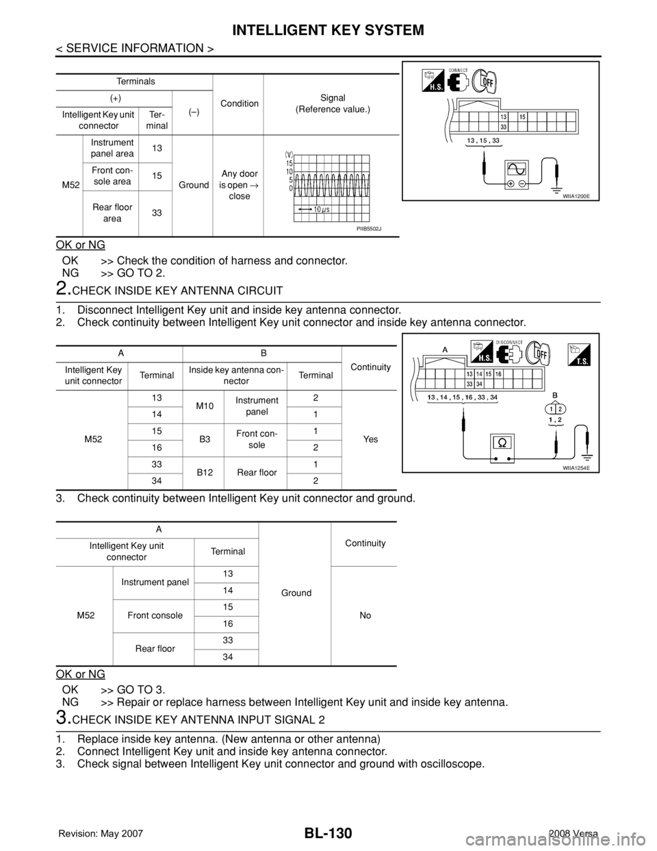
2.CHECK INSIDE KEY ANTENNA CIRCUIT
1. Disconnect Intelligent Key unit and inside key antenna connector.
2. Check continuity between Intelligent Key unit connector and inside key antenna connector.
3. Check continuity between Intelligent Key unit connector and ground.
OK or NG
OK >> GO TO 3.
NG >> Repair or replace harness between Intelligent Key unit and inside key antenna.
3.CHECK INSIDE KEY ANTENNA INPUT SIGNAL 2
1. Replace inside key antenna. (New antenna or other antenna)
2. Connect Intelligent Key unit and inside key antenna connector.
3. Check signal between Intelligent Key unit connector and ground with oscilloscope.
Te r m i n a l s
ConditionSignal
(Reference value.) (+)
(–)
Intelligent Key unit
connectorTe r -
minal
M52Instrument
panel area13
GroundAny door
is open →
close Front con-
sole area15
Rear floor
area33
WIIA1200E
PIIB5502J
AB
Continuity
Intelligent Key
unit connectorTe r m i n a lInside key antenna con-
nectorTe r m i n a l
M5213
M10Instrument
panel2
Ye s 14 1
15
B3Front con-
sole1
16 2
33
B12 Rear floor1
34 2
A
GroundContinuity
Intelligent Key unit
connectorTe r m i n a l
M52Instrument panel13
No 14
Front console15
16
Rear floor33
34
WIIA1254E
Page 565 of 2771
INTELLIGENT KEY SYSTEM
BL-131
< SERVICE INFORMATION >
C
D
E
F
G
H
J
K
L
MA
B
BL
N
O
P
OK or NG
OK >> Replace malfunction inside key antenna.
NG >> Replace Intelligent Key unit.
Steering Lock Solenoid CheckINFOID:0000000001704028
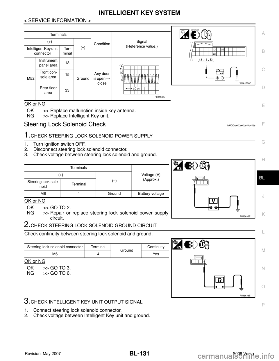
1.CHECK STEERING LOCK SOLENOID POWER SUPPLY
1. Turn ignition switch OFF.
2. Disconnect steering lock solenoid connector.
3. Check voltage between steering lock solenoid and ground.
OK or NG
OK >> GO TO 2.
NG >> Repair or replace steering lock solenoid power supply
circuit.
2.CHECK STEERING LOCK SOLENOID GROUND CIRCUIT
Check continuity between steering lock solenoid and ground.
OK or NG
OK >> GO TO 3.
NG >> GO TO 6.
3.CHECK INTELLIGENT KEY UNIT OUTPUT SIGNAL
1. Connect steering lock solenoid connector.
2. Check voltage between Intelligent Key unit and ground.
Te r m i n a l s
ConditionSignal
(Reference value.) (+)
(–)
Intelligent Key unit
connectorTe r -
minal
M52Instrument
panel area13
GroundAny door
is open →
close Front con-
sole area15
Rear floor
area33
WIIA1200E
PIIB5502J
Te r m i n a l s
Voltage (V)
(Approx.) (+)
(–)
Steering lock sole-
noidTe r m i n a l
M6 1 Ground Battery voltage
PIIB6632E
Steering lock solenoid connector Terminal
GroundContinuity
M6 4 Yes
PIIB6633E
Page 566 of 2771
BL-132
< SERVICE INFORMATION >
INTELLIGENT KEY SYSTEM
OK or NG
OK >> GO TO 4.
NG >> GO TO 6.
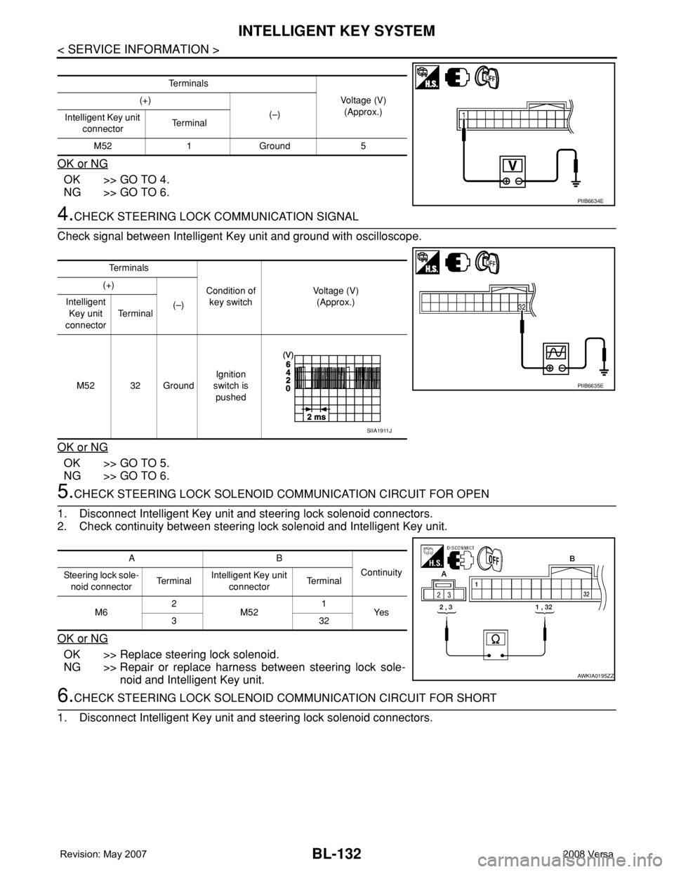
4.CHECK STEERING LOCK COMMUNICATION SIGNAL
Check signal between Intelligent Key unit and ground with oscilloscope.
OK or NG
OK >> GO TO 5.
NG >> GO TO 6.
5.CHECK STEERING LOCK SOLENOID COMMUNICATION CIRCUIT FOR OPEN
1. Disconnect Intelligent Key unit and steering lock solenoid connectors.
2. Check continuity between steering lock solenoid and Intelligent Key unit.
OK or NG
OK >> Replace steering lock solenoid.
NG >> Repair or replace harness between steering lock sole-
noid and Intelligent Key unit.
6.CHECK STEERING LOCK SOLENOID COMMUNICATION CIRCUIT FOR SHORT
1. Disconnect Intelligent Key unit and steering lock solenoid connectors.
Te r m i n a l s
Voltage (V)
(Approx.) (+)
(–)
Intelligent Key unit
connectorTe r m i n a l
M52 1 Ground 5
PIIB6634E
Te r m i n a l s
Condition of
key switchVoltage (V)
(Approx.) (+)
(–) Intelligent
Key unit
connectorTe r m i n a l
M52 32 GroundIgnition
switch is
pushed
PIIB6635E
SIIA1911J
AB
Continuity
Steering lock sole-
noid connectorTe r m i n a lIntelligent Key unit
connectorTe r m i n a l
M62
M521
Ye s
332
AWKIA0195ZZ