Page 527 of 2771
INTELLIGENT KEY SYSTEM
BL-93
< SERVICE INFORMATION >
C
D
E
F
G
H
J
K
L
MA
B
BL
N
O
P
WIWA2277E
Page 528 of 2771
BL-94
< SERVICE INFORMATION >
INTELLIGENT KEY SYSTEM
WIWA2285E
Page 529 of 2771
INTELLIGENT KEY SYSTEM
BL-95
< SERVICE INFORMATION >
C
D
E
F
G
H
J
K
L
MA
B
BL
N
O
P
WIWA2286E
Page 530 of 2771
BL-96
< SERVICE INFORMATION >
INTELLIGENT KEY SYSTEM
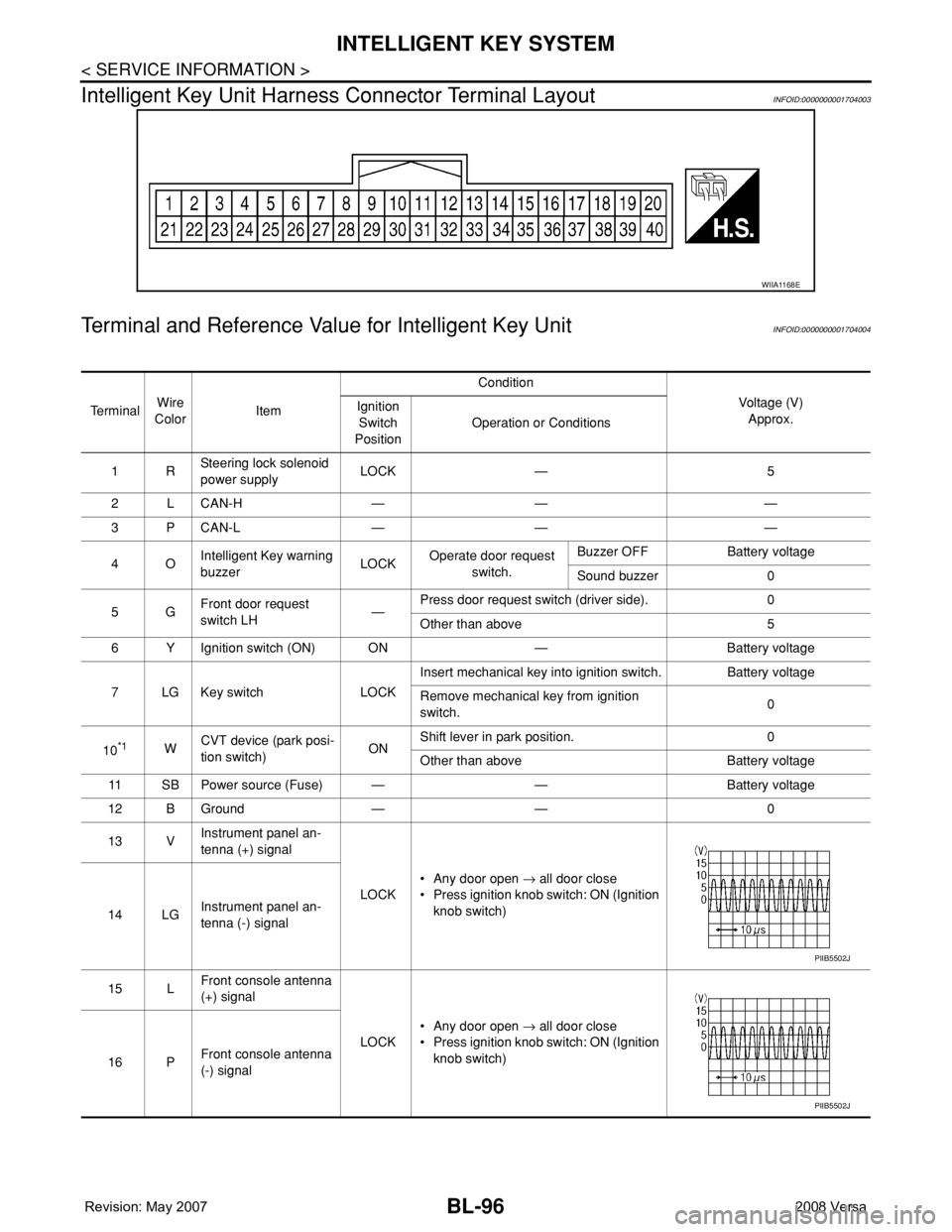
Intelligent Key Unit Harness Connector Terminal Layout
INFOID:0000000001704003
Terminal and Reference Value for Intelligent Key UnitINFOID:0000000001704004
WIIA1168E
Te r m i n a lWire
ColorItemCondition
Voltage (V)
Approx. Ignition
Switch
PositionOperation or Conditions
1RSteering lock solenoid
power supplyLOCK — 5
2 L CAN-H — — —
3 P CAN-L — — —
4OIntelligent Key warning
buzzerLOCKOperate door request
switch.Buzzer OFF Battery voltage
Sound buzzer 0
5GFront door request
switch LH—Press door request switch (driver side). 0
Other than above 5
6 Y Ignition switch (ON) ON — Battery voltage
7 LG Key switch LOCKInsert mechanical key into ignition switch. Battery voltage
Remove mechanical key from ignition
switch.0
10
*1WCVT device (park posi-
tion switch)ONShift lever in park position. 0
Other than above Battery voltage
11 SB Power source (Fuse) — — Battery voltage
12 B Ground — — 0
13 VInstrument panel an-
tenna (+) signal
LOCK• Any door open → all door close
• Press ignition knob switch: ON (Ignition
knob switch)
14 LGInstrument panel an-
tenna (-) signal
15 LFront console antenna
(+) signal
LOCK• Any door open → all door close
• Press ignition knob switch: ON (Ignition
knob switch)
16 PFront console antenna
(-) signal
PIIB5502J
PIIB5502J
Page 531 of 2771
INTELLIGENT KEY SYSTEM
BL-97
< SERVICE INFORMATION >
C
D
E
F
G
H
J
K
L
MA
B
BL
N
O
P
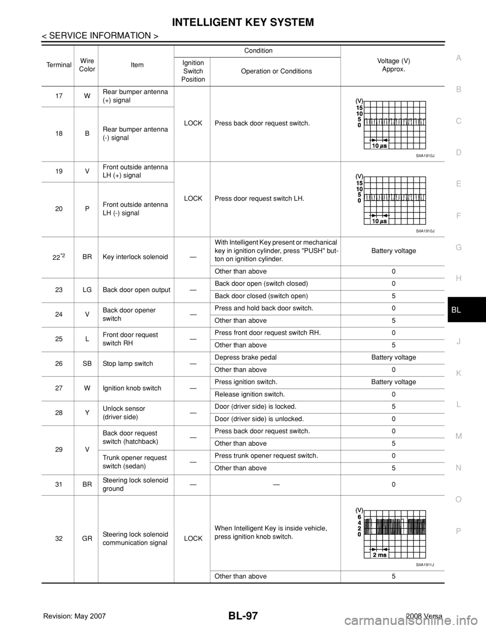
17 WRear bumper antenna
(+) signal
LOCK Press back door request switch.
18 BRear bumper antenna
(-) signal
19 VFront outside antenna
LH (+) signal
LOCK Press door request switch LH.
20 PFront outside antenna
LH (-) signal
22
*2BR Key interlock solenoid —With Intelligent Key present or mechanical
key in ignition cylinder, press "PUSH" but-
ton on ignition cylinder.Battery voltage
Other than above 0
23 LG Back door open output —Back door open (switch closed) 0
Back door closed (switch open) 5
24 VBack door opener
switch—Press and hold back door switch. 0
Other than above 5
25 LFront door request
switch RH—Press front door request switch RH. 0
Other than above 5
26 SB Stop lamp switch —Depress brake pedal Battery voltage
Other than above 0
27 W Ignition knob switch —Press ignition switch. Battery voltage
Release ignition switch. 0
28 YUnlock sensor
(driver side)—Door (driver side) is locked. 5
Door (driver side) is unlocked. 0
29 VBack door request
switch (hatchback)—Press back door request switch. 0
Other than above 5
Trunk opener request
switch (sedan)—Press trunk opener request switch. 0
Other than above 5
31 BRSteering lock solenoid
ground—— 0
32 GRSteering lock solenoid
communication signalLOCKWhen Intelligent Key is inside vehicle,
press ignition knob switch.
Other than above 5 TerminalWire
ColorItemCondition
Voltage (V)
Approx. Ignition
Switch
PositionOperation or Conditions
SIIA1910J
SIIA1910J
SIIA1911J
Page 532 of 2771
BL-98
< SERVICE INFORMATION >
INTELLIGENT KEY SYSTEM
*1: With continuously variable transmission (CVT).
*2: With manual transmission (M/T).
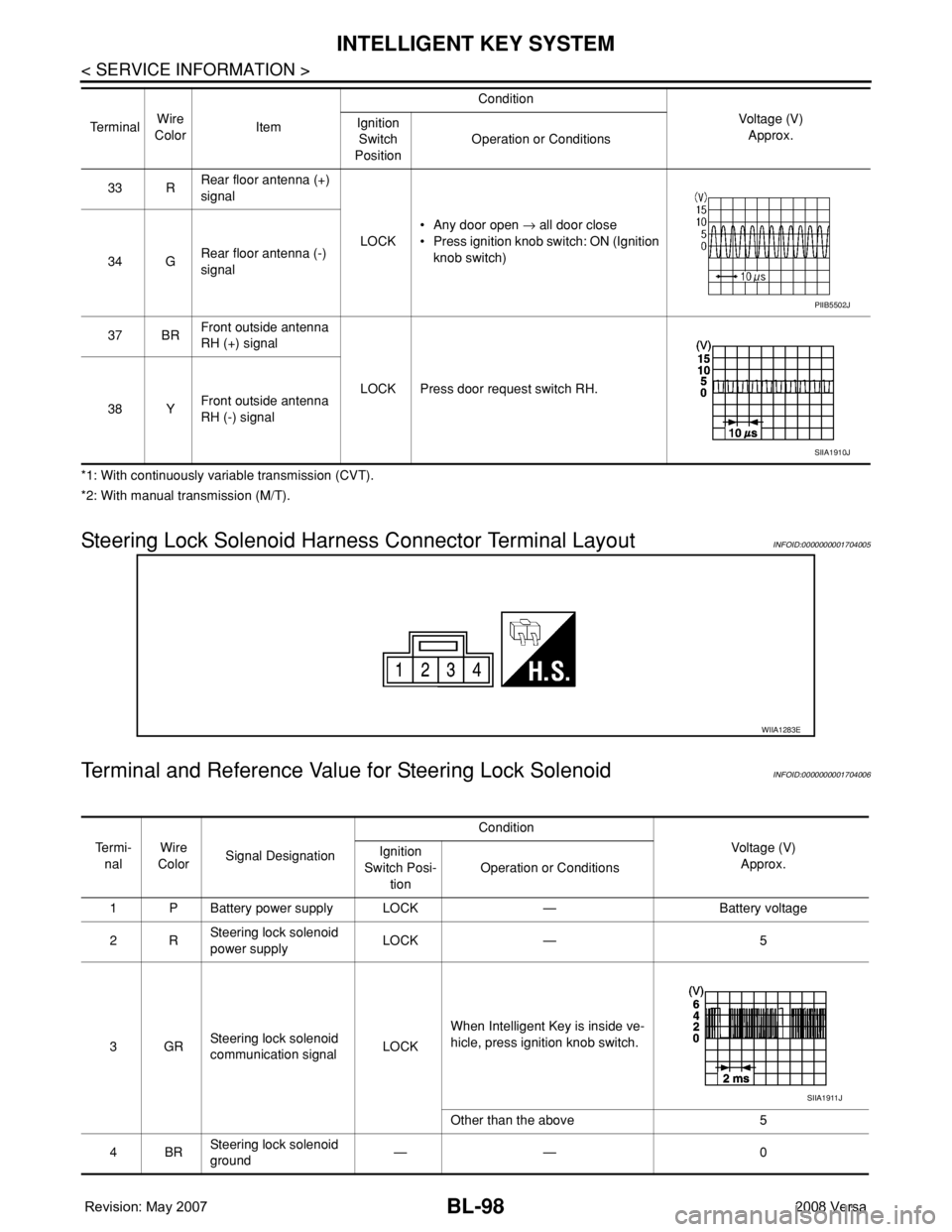
Steering Lock Solenoid Harness Connector Terminal LayoutINFOID:0000000001704005
Terminal and Reference Value for Steering Lock SolenoidINFOID:0000000001704006
33 RRear floor antenna (+)
signal
LOCK• Any door open → all door close
• Press ignition knob switch: ON (Ignition
knob switch)
34 GRear floor antenna (-)
signal
37 BRFront outside antenna
RH (+) signal
LOCK Press door request switch RH.
38 YFront outside antenna
RH (-) signal Te r m i n a lWire
ColorItemCondition
Voltage (V)
Approx. Ignition
Switch
PositionOperation or Conditions
PIIB5502J
SIIA1910J
WIIA1283E
Te r m i -
nalWire
ColorSignal DesignationCondition
Voltage (V)
Approx. Ignition
Switch Posi-
tionOperation or Conditions
1 P Battery power supply LOCK — Battery voltage
2RSteering lock solenoid
power supplyLOCK — 5
3GRSteering lock solenoid
communication signalLOCKWhen Intelligent Key is inside ve-
hicle, press ignition knob switch.
Other than the above 5
4BRSteering lock solenoid
ground—— 0
SIIA1911J
Page 533 of 2771
INTELLIGENT KEY SYSTEM
BL-99
< SERVICE INFORMATION >
C
D
E
F
G
H
J
K
L
MA
B
BL
N
O
P
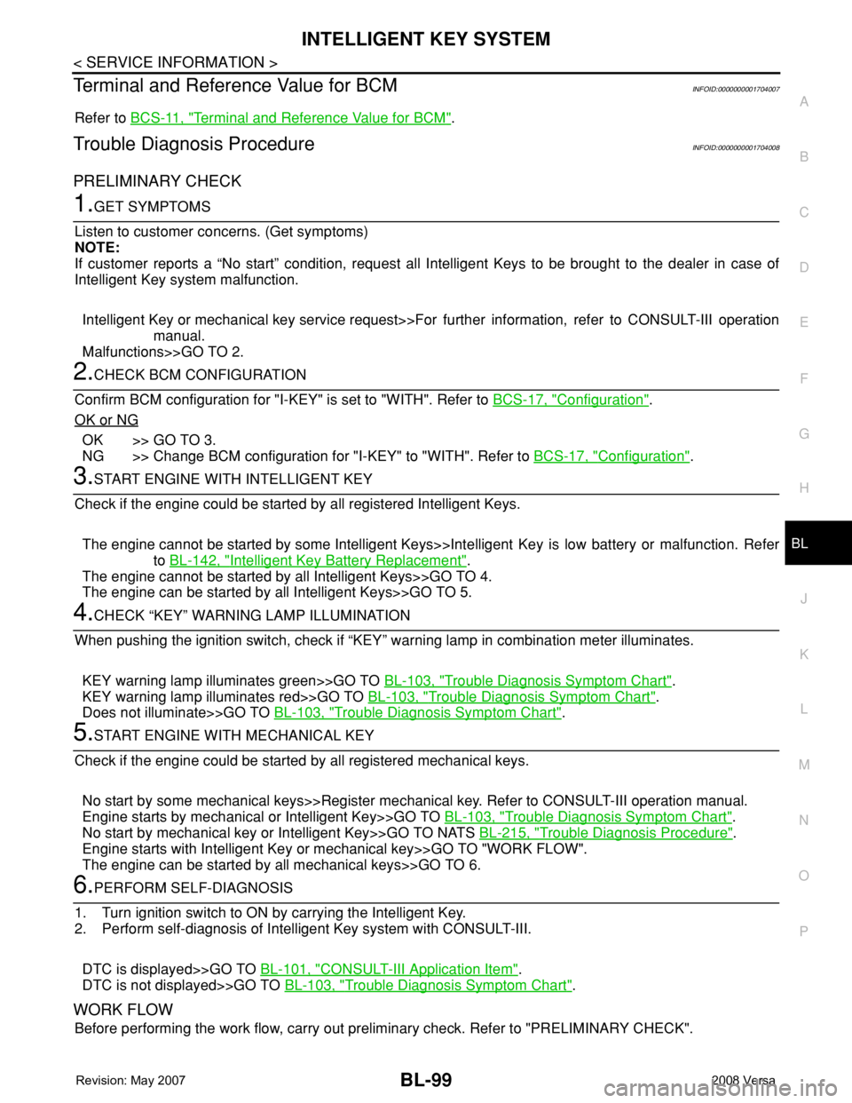
Terminal and Reference Value for BCMINFOID:0000000001704007
Refer to BCS-11, "Terminal and Reference Value for BCM".
Trouble Diagnosis ProcedureINFOID:0000000001704008
PRELIMINARY CHECK
1.GET SYMPTOMS
Listen to customer concerns. (Get symptoms)
NOTE:
If customer reports a “No start” condition, request all Intelligent Keys to be brought to the dealer in case of
Intelligent Key system malfunction.
Intelligent Key or mechanical key service request>>For further information, refer to CONSULT-III operation
manual.
Malfunctions>>GO TO 2.
2.CHECK BCM CONFIGURATION
Confirm BCM configuration for "I-KEY" is set to "WITH". Refer to BCS-17, "
Configuration".
OK or NG
OK >> GO TO 3.
NG >> Change BCM configuration for "I-KEY" to "WITH". Refer to BCS-17, "
Configuration".
3.START ENGINE WITH INTELLIGENT KEY
Check if the engine could be started by all registered Intelligent Keys.
The engine cannot be started by some Intelligent Keys>>Intelligent Key is low battery or malfunction. Refer
to BL-142, "
Intelligent Key Battery Replacement".
The engine cannot be started by all Intelligent Keys>>GO TO 4.
The engine can be started by all Intelligent Keys>>GO TO 5.
4.CHECK “KEY” WARNING LAMP ILLUMINATION
When pushing the ignition switch, check if “KEY” warning lamp in combination meter illuminates.
KEY warning lamp illuminates green>>GO TO BL-103, "
Trouble Diagnosis Symptom Chart".
KEY warning lamp illuminates red>>GO TO BL-103, "
Trouble Diagnosis Symptom Chart".
Does not illuminate>>GO TO BL-103, "
Trouble Diagnosis Symptom Chart".
5.START ENGINE WITH MECHANICAL KEY
Check if the engine could be started by all registered mechanical keys.
No start by some mechanical keys>>Register mechanical key. Refer to CONSULT-III operation manual.
Engine starts by mechanical or Intelligent Key>>GO TO BL-103, "
Trouble Diagnosis Symptom Chart".
No start by mechanical key or Intelligent Key>>GO TO NATS BL-215, "
Trouble Diagnosis Procedure".
Engine starts with Intelligent Key or mechanical key>>GO TO "WORK FLOW".
The engine can be started by all mechanical keys>>GO TO 6.
6.PERFORM SELF-DIAGNOSIS
1. Turn ignition switch to ON by carrying the Intelligent Key.
2. Perform self-diagnosis of Intelligent Key system with CONSULT-III.
DTC is displayed>>GO TO BL-101, "
CONSULT-III Application Item".
DTC is not displayed>>GO TO BL-103, "
Trouble Diagnosis Symptom Chart".
WORK FLOW
Before performing the work flow, carry out preliminary check. Refer to "PRELIMINARY CHECK".
Page 534 of 2771
BL-100
< SERVICE INFORMATION >
INTELLIGENT KEY SYSTEM
1.CHECK FUNCTION OF INTELLIGENT KEY SYSTEM
Check if the function related to Intelligent Key system operates normally.
All functions of Intelligent Key system do not operate>>GO TO BL-103, "
Trouble Diagnosis Symptom Chart".
Specific function of Intelligent Key system does not operate>>GO TO 2.
2.CHECK POWER DOOR LOCK OPERATION
Check if door lock/unlock function operates with door lock and unlock switch.
OK or NG
OK >> GO TO 3.
NG >> GO TO BL-22
.
3.CHECK DOOR REQUEST SWITCH OPERATION
Check if door lock/unlock function operates with request switch.
OK or NG
OK >> GO TO 4.
NG >> GO TO BL-103, "
Trouble Diagnosis Symptom Chart".
4.CHECK REMOTE KEYLESS FUNCTION
Check if the following function responds with Intelligent Key button.
• Door lock/unlock function
• Panic alarm function
OK or NG
OK >> GO TO 5.
NG >> GO TO BL-103, "
Trouble Diagnosis Symptom Chart".
5.CHECK HAZARD AND BUZZER REMINDER FUNCTION
Check if hazard and buzzer reminder function responds with the following switches.
• Door request switch
• Intelligent Key button
OK or NG
OK >> GO TO 6.
NG >> GO TO BL-103, "
Trouble Diagnosis Symptom Chart".
6.CHECK WARNING CHIME FUNCTION
Check if warning chime function operates normally according to system description. Refer to BL-76, "
System
Description".
OK or NG
OK >> GO TO 7.
NG >> GO TO BL-103, "
Trouble Diagnosis Symptom Chart".
7.CHECK WARNING LAMP FUNCTION
Check if warning lamp could be turn on normally according to system description. Refer to BL-76, "
System
Description".
OK or NG
OK >> End of inspection.
NG >> GO TO BL-103, "
Trouble Diagnosis Symptom Chart".
CONSULT-III Functions (INTELLIGENT KEY)INFOID:0000000001704009
CONSULT-III can display each diagnostic item using the diagnostic test modes as shown below.