2008 NISSAN LATIO engine coolant
[x] Cancel search: engine coolantPage 2183 of 2771
LT-46
< SERVICE INFORMATION >
FRONT FOG LAMP
1. Check continuity between front fog lamp harness connector and
ground.
OK or NG
OK >> Replace IPDM E/R. Refer to PG-26, "Removal and
Installation of IPDM E/R" .
NG >> Repair harness or connector.
Aiming AdjustmentINFOID:0000000001704409
The front fog lamp is a semi-sealed beam type which uses a replaceable halogen bulb. Before performing
aiming adjustment, make sure of the following.
• Keep all tires inflated to correct pressure.
• Place vehicle on level surface.
• Set that there is no-load in vehicle other than the driver (or equivalent weight placed in driver’s position).
Coolant, engine oil filled up to correct level and full fuel tank, spare tire, jack and tools are properly stowed.
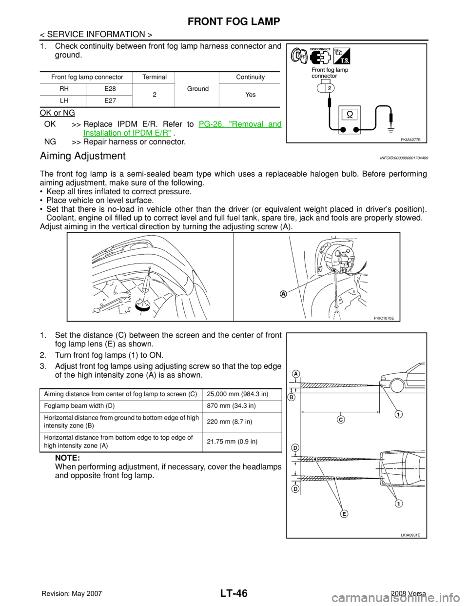
Adjust aiming in the vertical direction by turning the adjusting screw (A).
1. Set the distance (C) between the screen and the center of front
fog lamp lens (E) as shown.
2. Turn front fog lamps (1) to ON.
3. Adjust front fog lamps using adjusting screw so that the top edge
of the high intensity zone (A) is as shown.
NOTE:
When performing adjustment, if necessary, cover the headlamps
and opposite front fog lamp.
Front fog lamp connector Terminal
Ground Continuity
RH E28
2Yes
LH E27
PKIA6277E
PKIC1070E
Aiming distance from center of fog lamp to screen (C) 25,000 mm (984.3 in)
Foglamp beam width (D) 870 mm (34.3 in)
Horizontal distance from ground to bottom edge of high
intensity zone (B)220 mm (8.7 in)
Horizontal distance from bottom edge to top edge of
high intensity zone (A)21.75 mm (0.9 in)
LKIA0931E
Page 2252 of 2771
LU-2
< SERVICE INFORMATION >
PRECAUTIONS
SERVICE INFORMATION
PRECAUTIONS
Precaution for Supplemental Restraint System (SRS) "AIR BAG" and "SEAT BELT
PRE-TENSIONER"
INFOID:0000000001790697
The Supplemental Restraint System such as “AIR BAG” and “SEAT BELT PRE-TENSIONER”, used along
with a front seat belt, helps to reduce the risk or severity of injury to the driver and front passenger for certain
types of collision. This system includes seat belt switch inputs and dual stage front air bag modules. The SRS
system uses the seat belt switches to determine the front air bag deployment, and may only deploy one front
air bag, depending on the severity of a collision and whether the front occupants are belted or unbelted.
Information necessary to service the system safely is included in the SRS and SB section of this Service Man-
ual.
WARNING:
• To avoid rendering the SRS inoperative, which could increase the risk of personal injury or death in
the event of a collision which would result in air bag inflation, all maintenance must be performed by
an authorized NISSAN/INFINITI dealer.
• Improper maintenance, including incorrect removal and installation of the SRS, can lead to personal
injury caused by unintentional activation of the system. For removal of Spiral Cable and Air Bag
Module, see the SRS section.
• Do not use electrical test equipment on any circuit related to the SRS unless instructed to in this
Service Manual. SRS wiring harnesses can be identified by yellow and/or orange harnesses or har-
ness connectors.
Precaution for Liquid GasketINFOID:0000000001702514
LIQUID GASKET APPLICATION PROCEDURE
1. Remove old liquid gasket adhering to the liquid gasket application surface and the mating surface.
• Remove liquid gasket completely from the liquid gasket application surface, bolts, and bolt holes.
2. Wipe the liquid gasket application surface and the mating surface with white gasoline (lighting and heating
use) to remove adhering moisture, grease and foreign materials.
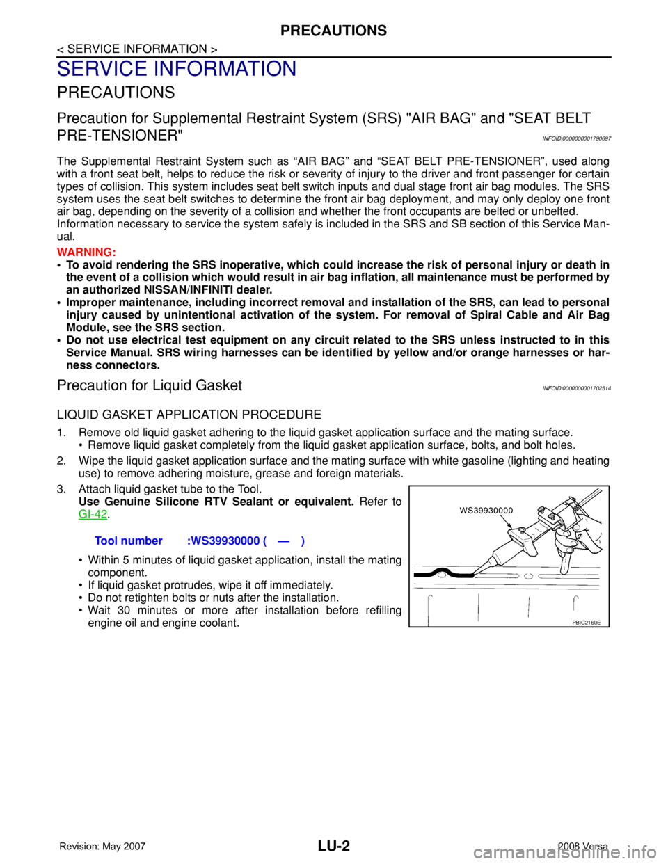
3. Attach liquid gasket tube to the Tool.
Use Genuine Silicone RTV Sealant or equivalent. Refer to
GI-42
.
• Within 5 minutes of liquid gasket application, install the mating
component.
• If liquid gasket protrudes, wipe it off immediately.
• Do not retighten bolts or nuts after the installation.
• Wait 30 minutes or more after installation before refilling
engine oil and engine coolant.Tool number :WS39930000 ( — )
PBIC2160E
Page 2256 of 2771
LU-6
< SERVICE INFORMATION >
ENGINE OIL
ENGINE OIL
InspectionINFOID:0000000001702518
ENGINE OIL LEVEL
NOTE:
Before starting engine, park vehicle on a level surface and check the engine oil level. If engine is already
started, stop it and allow 10 minutes before checking.
1. Pull out oil level gauge and wipe it clean.
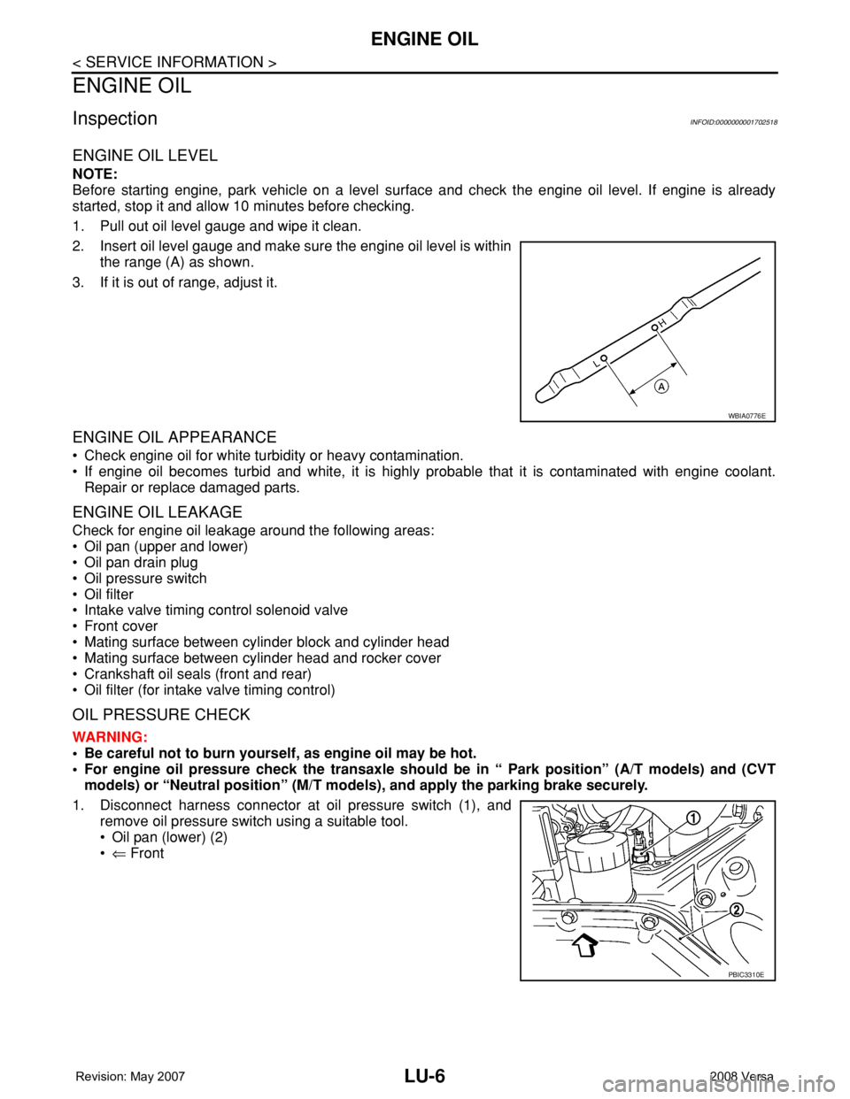
2. Insert oil level gauge and make sure the engine oil level is within
the range (A) as shown.
3. If it is out of range, adjust it.
ENGINE OIL APPEARANCE
• Check engine oil for white turbidity or heavy contamination.
• If engine oil becomes turbid and white, it is highly probable that it is contaminated with engine coolant.
Repair or replace damaged parts.
ENGINE OIL LEAKAGE
Check for engine oil leakage around the following areas:
• Oil pan (upper and lower)
• Oil pan drain plug
• Oil pressure switch
• Oil filter
• Intake valve timing control solenoid valve
• Front cover
• Mating surface between cylinder block and cylinder head
• Mating surface between cylinder head and rocker cover
• Crankshaft oil seals (front and rear)
• Oil filter (for intake valve timing control)
OIL PRESSURE CHECK
WARNING:
• Be careful not to burn yourself, as engine oil may be hot.
• For engine oil pressure check the transaxle should be in “ Park position” (A/T models) and (CVT
models) or “Neutral position” (M/T models), and apply the parking brake securely.
1. Disconnect harness connector at oil pressure switch (1), and
remove oil pressure switch using a suitable tool.
• Oil pan (lower) (2)
•⇐ Front
WBIA0776E
PBIC3310E
Page 2261 of 2771

MA-1
MAINTENANCE
C
D
E
F
G
H
I
J
K
M
SECTION MA
A
B
MA
N
O
P
CONTENTS
MAINTENANCE
SERVICE INFORMATION ............................2
PRECAUTIONS ...................................................2
Precaution for Supplemental Restraint System
(SRS) "AIR BAG" and "SEAT BELT PRE-TEN-
SIONER" ...................................................................
2
PREPARATION ...................................................3
Special Service Tool .................................................3
Commercial Service Tool ..........................................3
GENERAL MAINTENANCE ................................4
Explanation of General Maintenance ........................4
General Maintenance ................................................4
PERIODIC MAINTENANCE ................................6
Introduction of Periodic Maintenance ........................6
Schedule 1 ................................................................6
Schedule 2 ................................................................8
RECOMMENDED FLUIDS AND LUBRI-
CANTS ................................................................
10
Fluids and Lubricants ..............................................10
SAE Viscosity Number ............................................10
Anti-freeze Coolant Mixture Ratio ...........................11
ENGINE MAINTENANCE ...................................12
Drive Belts ...............................................................12
Checking Drive Belts ...............................................12
Tension Adjustment ................................................12
Changing Engine Coolant .......................................12
Inspection ................................................................14
Checking Fuel Line ..................................................14
Changing Air Cleaner Filter .....................................14
Changing Engine Oil ................................................15
Engine Oil Filter .......................................................16
Changing Spark Plugs .............................................17
Checking EVAP Vapor Line .....................................18
CHASSIS AND BODY MAINTENANCE ...........19
Changing In-cabin Microfilter ...................................19
Checking Exhaust System .......................................19
Checking CVT Fluid .................................................19
Changing CVT Fluid ................................................20
Checking Clutch Fluid Level and Leaks ..................21
Checking Clutch System .........................................21
Checking M/T Oil .....................................................21
Changing M/T Oil .....................................................21
Checking A/T Fluid ..................................................22
Changing A/T Fluid ..................................................22
Balancing Wheels ....................................................23
Rotation ...................................................................23
Checking Brake Fluid Level and Leaks ...................23
Checking Brake Line and Cables ............................24
Changing Brake Fluid ..............................................24
Checking Disc Brake ...............................................24
Axle and Suspension Parts .....................................25
Drive Shaft ...............................................................26
Lubricating Locks, Hinges and Hood Latch .............27
Checking Seat Belts, Buckles, Retractors, An-
chors and Adjusters .................................................
27
Page 2263 of 2771
PREPARATION
MA-3
< SERVICE INFORMATION >
C
D
E
F
G
H
I
J
K
MA
B
MA
N
O
P
PREPARATION
Special Service ToolINFOID:0000000001704718
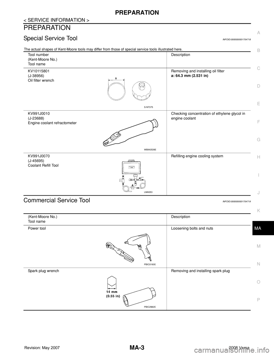
The actual shapes of Kent-Moore tools may differ from those of special service tools illustrated here.
Commercial Service ToolINFOID:0000000001704719
Tool number
(Kent-Moore No.)
Tool nameDescription
KV10115801
(J-38956)
Oil filter wrenchRemoving and installing oil filter
a: 64.3 mm (2.531 in)
KV991J0010
(J-23688)
Engine coolant refractometerChecking concentration of ethylene glycol in
engine coolant
KV991J0070
(J-45695)
Coolant Refill ToolRefilling engine cooling system
S-NT375
WBIA0539E
LMA053
(Kent-Moore No.)
Tool nameDescription
Power toolLoosening bolts and nuts
Spark plug wrench Removing and installing spark plug
PBIC0190E
PBIC2982E
Page 2265 of 2771
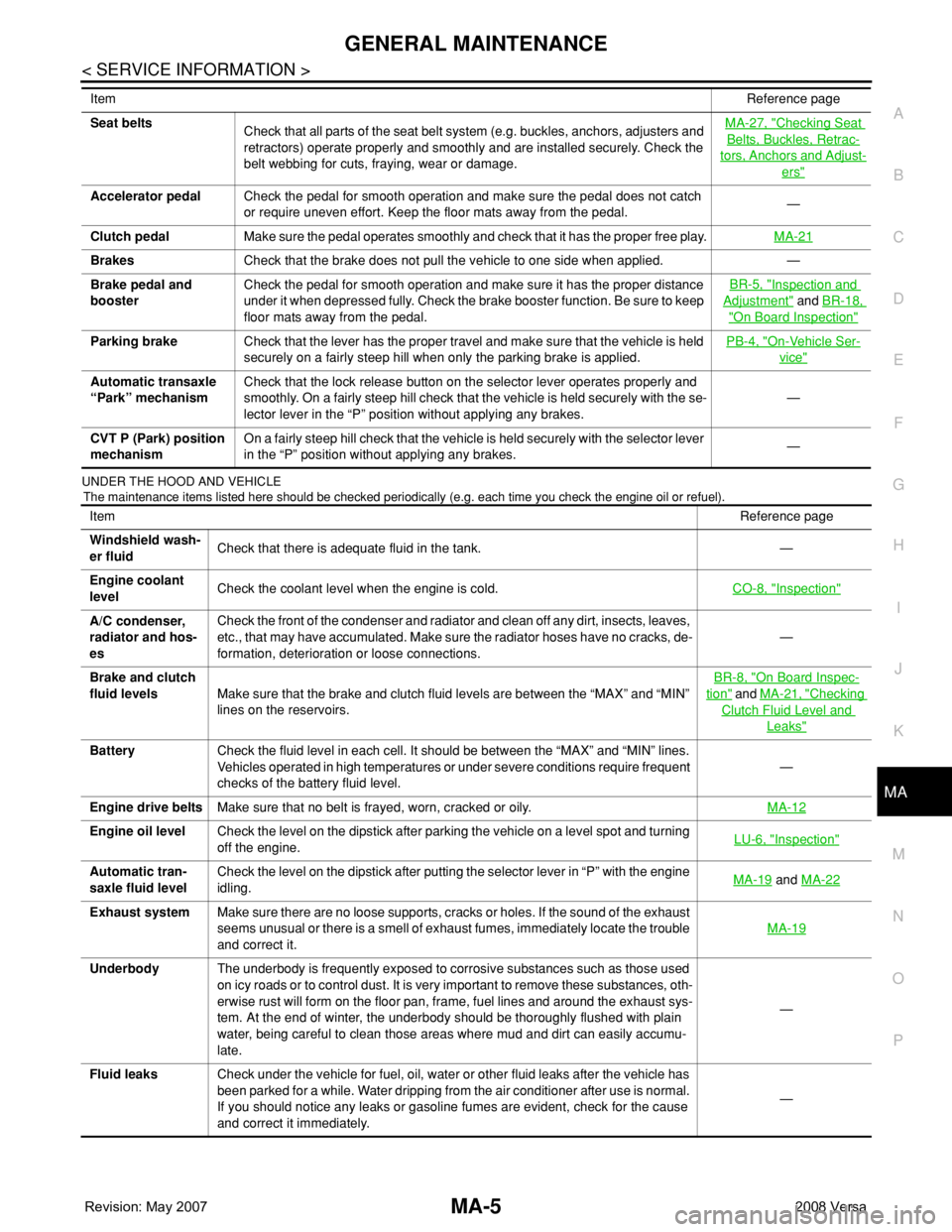
GENERAL MAINTENANCE
MA-5
< SERVICE INFORMATION >
C
D
E
F
G
H
I
J
K
MA
B
MA
N
O
P
UNDER THE HOOD AND VEHICLE
The maintenance items listed here should be checked periodically (e.g. each time you check the engine oil or refuel).
Seat belts
Check that all parts of the seat belt system (e.g. buckles, anchors, adjusters and
retractors) operate properly and smoothly and are installed securely. Check the
belt webbing for cuts, fraying, wear or damage.MA-27, "Checking Seat
Belts, Buckles, Retrac-
tors, Anchors and Adjust-
ers"
Accelerator pedalCheck the pedal for smooth operation and make sure the pedal does not catch
or require uneven effort. Keep the floor mats away from the pedal.—
Clutch pedalMake sure the pedal operates smoothly and check that it has the proper free play.MA-21
BrakesCheck that the brake does not pull the vehicle to one side when applied. —
Brake pedal and
boosterCheck the pedal for smooth operation and make sure it has the proper distance
under it when depressed fully. Check the brake booster function. Be sure to keep
floor mats away from the pedal.BR-5, "
Inspection and
Adjustment" and BR-18,
"On Board Inspection"
Parking brakeCheck that the lever has the proper travel and make sure that the vehicle is held
securely on a fairly steep hill when only the parking brake is applied.PB-4, "On-Vehicle Ser-
vice"
Automatic transaxle
“Park” mechanismCheck that the lock release button on the selector lever operates properly and
smoothly. On a fairly steep hill check that the vehicle is held securely with the se-
lector lever in the “P” position without applying any brakes.—
CVT P (Park) position
mechanismOn a fairly steep hill check that the vehicle is held securely with the selector lever
in the “P” position without applying any brakes.— ItemReference page
ItemReference page
Windshield wash-
er fluidCheck that there is adequate fluid in the tank. —
Engine coolant
levelCheck the coolant level when the engine is cold.CO-8, "
Inspection"
A/C condenser,
radiator and hos-
esCheck the front of the condenser and radiator and clean off any dirt, insects, leaves,
etc., that may have accumulated. Make sure the radiator hoses have no cracks, de-
formation, deterioration or loose connections.—
Brake and clutch
fluid levelsMake sure that the brake and clutch fluid levels are between the “MAX” and “MIN”
lines on the reservoirs.BR-8, "
On Board Inspec-
tion" and MA-21, "Checking
Clutch Fluid Level and
Leaks"
BatteryCheck the fluid level in each cell. It should be between the “MAX” and “MIN” lines.
Vehicles operated in high temperatures or under severe conditions require frequent
checks of the battery fluid level.—
Engine drive beltsMake sure that no belt is frayed, worn, cracked or oily.MA-12
Engine oil levelCheck the level on the dipstick after parking the vehicle on a level spot and turning
off the engine.LU-6, "Inspection"
Automatic tran-
saxle fluid levelCheck the level on the dipstick after putting the selector lever in “P” with the engine
idling.MA-19 and MA-22
Exhaust systemMake sure there are no loose supports, cracks or holes. If the sound of the exhaust
seems unusual or there is a smell of exhaust fumes, immediately locate the trouble
and correct it.MA-19
UnderbodyThe underbody is frequently exposed to corrosive substances such as those used
on icy roads or to control dust. It is very important to remove these substances, oth-
erwise rust will form on the floor pan, frame, fuel lines and around the exhaust sys-
tem. At the end of winter, the underbody should be thoroughly flushed with plain
water, being careful to clean those areas where mud and dirt can easily accumu-
late.—
Fluid leaksCheck under the vehicle for fuel, oil, water or other fluid leaks after the vehicle has
been parked for a while. Water dripping from the air conditioner after use is normal.
If you should notice any leaks or gasoline fumes are evident, check for the cause
and correct it immediately.—
Page 2266 of 2771
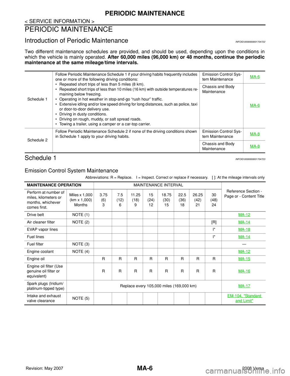
MA-6
< SERVICE INFORMATION >
PERIODIC MAINTENANCE
PERIODIC MAINTENANCE
Introduction of Periodic MaintenanceINFOID:0000000001704722
Two different maintenance schedules are provided, and should be used, depending upon the conditions in
which the vehicle is mainly operated. After 60,000 miles (96,000 km) or 48 months, continue the periodic
maintenance at the same mileage/time intervals.
Schedule 1INFOID:0000000001704723
Emission Control System Maintenance
Abbreviations: R = Replace. I = Inspect. Correct or replace if necessary. [ ]: At the mileage intervals only
Schedule 1Follow Periodic Maintenance Schedule 1 if your driving habits frequently includes
one or more of the following driving conditions:
• Repeated short trips of less than 5 miles (8 km).
• Repeated short trips of less than 10 miles (16 km) with outside temperatures re-
maining below freezing.
• Operating in hot weather in stop-and-go “rush hour” traffic.
• Extensive idling and/or low speed driving for long distances, such as police, taxi
or door-to-door delivery use.
• Driving in dusty conditions.
• Driving on rough, muddy, or salt spread roads.
• Towing a trailer, using a camper or a car-top carrier.Emission Control Sys-
tem MaintenanceMA-6
Chassis and Body
Maintenance
MA-6
Schedule 2Follow Periodic Maintenance Schedule 2 if none of the driving conditions shown
in Schedule 1 apply to your driving habits.Emission Control Sys-
tem MaintenanceMA-8Chassis and Body
MaintenanceMA-8
MAINTENANCE OPERATIONMAINTENANCE INTERVAL
Reference Section -
Page or - Content Title Perform at number of
miles, kilometers or
months, whichever
comes first.Miles x 1,000
(km x 1,000)
Months3.75
(6)
37.5
(12)
611 . 2 5
(18)
915
(24)
1218.75
(30)
1522.5
(36)
1826.25
(42)
2130
(48)
24
Drive belt NOTE (1)MA-12
Air cleaner filter NOTE (2) [R]MA-14
EVAP vapor linesI*MA-18
Fuel linesI*MA-14
Fuel filter NOTE (3)—
Engine coolant NOTE (4)MA-12
Engine oil R R R R R R R RMA-15
Engine oil filter (Use
genuine oil filter or
equivalent)RRRRRRRRMA-16
Spark plugs (Iridium/
platinum-tipped type)Replace every 105,000 miles (169,000 km)MA-17
Intake and exhaust
valve clearance NOTE (5)EM-104, "Standard
and Limit"
Page 2267 of 2771
![NISSAN LATIO 2008 Service Repair Manual PERIODIC MAINTENANCE
MA-7
< SERVICE INFORMATION >
C
D
E
F
G
H
I
J
K
MA
B
MA
N
O
P
Abbreviations: R = Replace. I = Inspect. Correct or replace if necessary. [ ]: At the mileage intervals only
(1) After NISSAN LATIO 2008 Service Repair Manual PERIODIC MAINTENANCE
MA-7
< SERVICE INFORMATION >
C
D
E
F
G
H
I
J
K
MA
B
MA
N
O
P
Abbreviations: R = Replace. I = Inspect. Correct or replace if necessary. [ ]: At the mileage intervals only
(1) After](/manual-img/5/57360/w960_57360-2266.png)
PERIODIC MAINTENANCE
MA-7
< SERVICE INFORMATION >
C
D
E
F
G
H
I
J
K
MA
B
MA
N
O
P
Abbreviations: R = Replace. I = Inspect. Correct or replace if necessary. [ ]: At the mileage intervals only
(1) After 60,000 miles (96,000 km) or 48 months, inspect every 15,000 miles (24,000 km) or 12 months. Replace the drive belts if found
damaged.
(2) If operating mainly in dusty conditions, more frequent maintenance may be required.
(3) Maintenance-free item. For service procedures, go to the FL section.
(4) After 60,000 miles (96,000 km) or 48 months, replace every 30,000 miles (48,000 km) or 24 months.
(5) If valve noise increases, inspect valve clearance.
* Maintenance items and intervals with “*” are recommended by NISSAN for reliable vehicle operation. The owner need not perform
such maintenance in order to maintain the emission warranty or manufacturer recall liability. Other maintenance items and intervals are
required.
Chassis and Body Maintenance
Abbreviations: R = Replace. I = Inspect. Correct or replace if necessary. L = Lubricate.
MAINTENANCE OPERATIONMAINTENANCE INTERVAL
Reference Section -
Page or - Content Title Perform at number of
miles, kilometers or
months, whichever
comes first.Miles x
1,000
(km x
1,000)
Months33.75
(54)
2737.5
(60)
3041.25
(66)
3345
(72)
3648.75
(78)
3952.5
(84)
4256.25
(90)
4560
(96)
48
Drive beltNOTE
(1)I*MA-12
Air cleaner filterNOTE
(2)[R]MA-14
EVAP vapor linesI*MA-18
Fuel linesI*MA-14
Fuel filterNOTE
(3)—
Engine coolantNOTE
(4)R*MA-12
Engine oil R R R R R R R RMA-15
Engine oil filter (Use
genuine oil filter or
equivalent)R R R R RRRRMA-16
Spark plugs (Iridium/
platinum-tipped type)Replace every 105,000 miles (169,000 km)MA-17
Intake and exhaust
valve clearance NOTE
(5)EM-104
MAINTENANCE OPERATIONMAINTENANCE INTERVAL
Reference
Section -
Page or -
Content Title Perform at number of
miles, kilometers or
months, whichever
comes first.Miles x
1,000
(km x
1,000)
Months3.75
(6)
37.5
(12)
611 . 2 5
(18)
915
(24)
1218.75
(30)
1522.5
(36)
1826.25
(42)
2130
(48)
24
Brake lines & cables I IMA-24
Brake pads, rotors,
drums & liningsIIIIMA-24
Manual transaxle oil or
automatic transaxle
fluidNOTE (1) I IMA-19 , MA-
22 or MA-21
CVT fluid NOTE (2) I I
Steering gear & link-
age, axle & suspen-
sion partsIIIIMA-25
, PS-
12
Tire rotation NOTE (3)WT-6
Front drive shaft boots I I I IMA-26