2008 NISSAN LATIO engine coolant
[x] Cancel search: engine coolantPage 1496 of 2771
EC-422
< SERVICE INFORMATION >
DTC P1217 ENGINE OVER TEMPERATURE
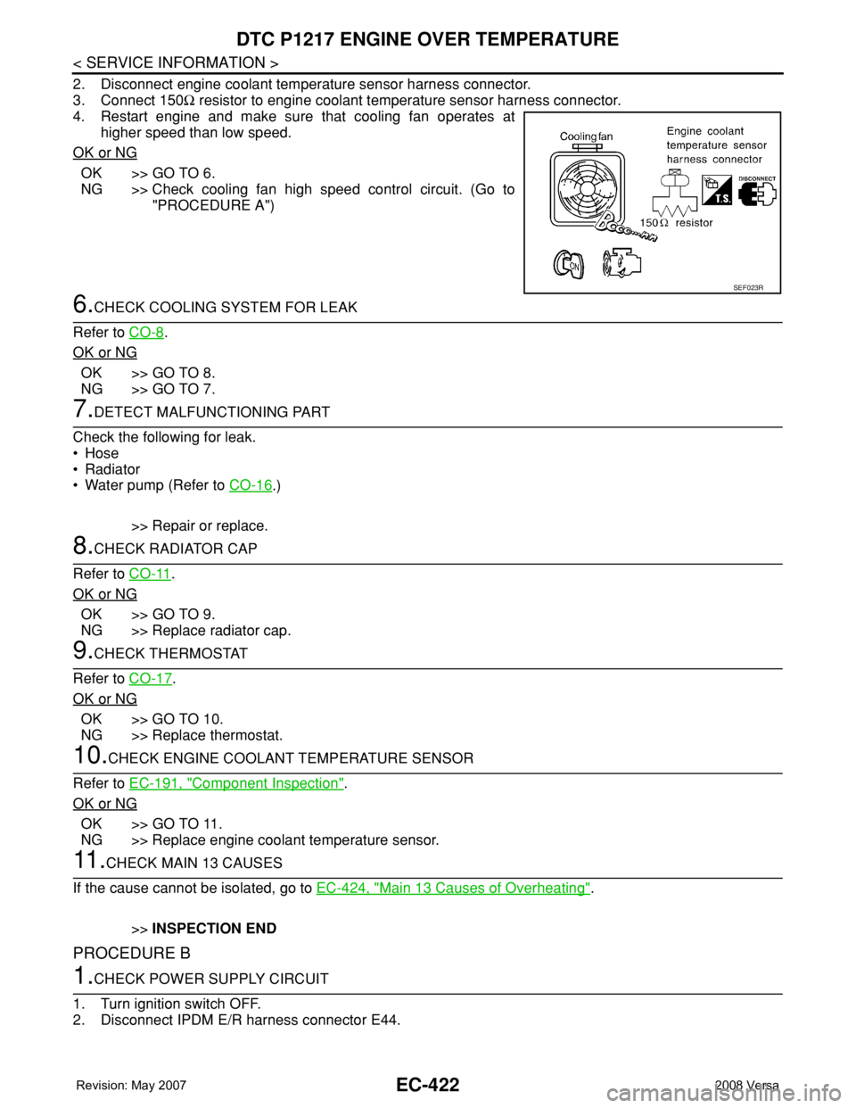
2. Disconnect engine coolant temperature sensor harness connector.
3. Connect 150Ω resistor to engine coolant temperature sensor harness connector.
4. Restart engine and make sure that cooling fan operates at
higher speed than low speed.
OK or NG
OK >> GO TO 6.
NG >> Check cooling fan high speed control circuit. (Go to
"PROCEDURE A")
6.CHECK COOLING SYSTEM FOR LEAK
Refer to CO-8
.
OK or NG
OK >> GO TO 8.
NG >> GO TO 7.
7.DETECT MALFUNCTIONING PART
Check the following for leak.
•Hose
• Radiator
• Water pump (Refer to CO-16
.)
>> Repair or replace.
8.CHECK RADIATOR CAP
Refer to CO-11
.
OK or NG
OK >> GO TO 9.
NG >> Replace radiator cap.
9.CHECK THERMOSTAT
Refer to CO-17
.
OK or NG
OK >> GO TO 10.
NG >> Replace thermostat.
10.CHECK ENGINE COOLANT TEMPERATURE SENSOR
Refer to EC-191, "
Component Inspection".
OK or NG
OK >> GO TO 11.
NG >> Replace engine coolant temperature sensor.
11 .CHECK MAIN 13 CAUSES
If the cause cannot be isolated, go to EC-424, "
Main 13 Causes of Overheating".
>>INSPECTION END
PROCEDURE B
1.CHECK POWER SUPPLY CIRCUIT
1. Turn ignition switch OFF.
2. Disconnect IPDM E/R harness connector E44.
SEF023R
Page 1498 of 2771
EC-424
< SERVICE INFORMATION >
DTC P1217 ENGINE OVER TEMPERATURE
OK >> GO TO 6.
NG >> Replace cooling fan motor.
6.CHECK INTERMITTENT INCIDENT
Perform EC-136
.
OK or NG
OK >> Replace IPDM E/R. Refer to PG-26, "Removal and Installation of IPDM E/R".
NG >> Repair or replace harness or connector.
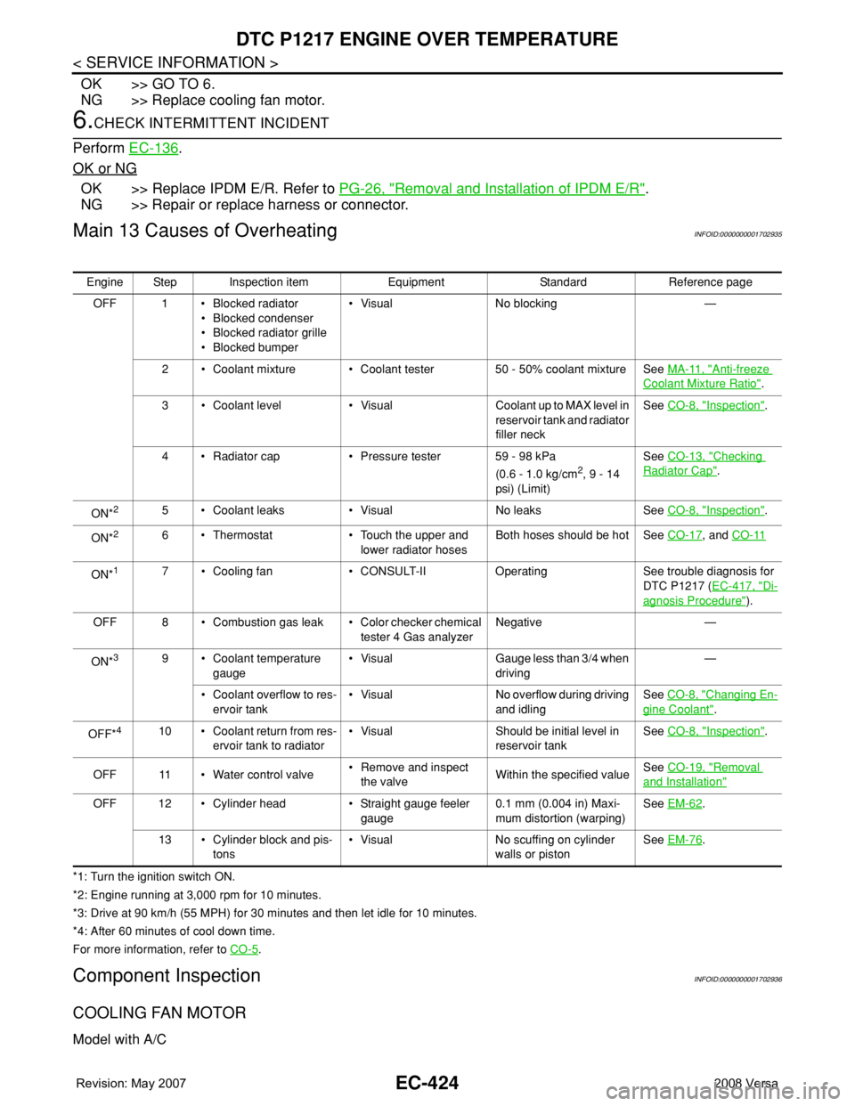
Main 13 Causes of OverheatingINFOID:0000000001702935
*1: Turn the ignition switch ON.
*2: Engine running at 3,000 rpm for 10 minutes.
*3: Drive at 90 km/h (55 MPH) for 30 minutes and then let idle for 10 minutes.
*4: After 60 minutes of cool down time.
For more information, refer to CO-5
.
Component InspectionINFOID:0000000001702936
COOLING FAN MOTOR
Model with A/C
Engine Step Inspection item Equipment Standard Reference page
OFF 1 • Blocked radiator
• Blocked condenser
• Blocked radiator grille
• Blocked bumper• Visual No blocking —
2 • Coolant mixture • Coolant tester 50 - 50% coolant mixture See MA-11, "
Anti-freeze
Coolant Mixture Ratio".
3 • Coolant level • Visual Coolant up to MAX level in
reservoir tank and radiator
filler neckSee CO-8, "
Inspection".
4 • Radiator cap • Pressure tester 59 - 98 kPa
(0.6 - 1.0 kg/cm
2, 9 - 14
psi) (Limit)See CO-13, "
Checking
Radiator Cap".
ON*
25 • Coolant leaks • Visual No leaks See CO-8, "Inspection".
ON*
26 • Thermostat • Touch the upper and
lower radiator hosesBoth hoses should be hot See CO-17, and CO-11
ON*17 • Cooling fan • CONSULT-II Operating See trouble diagnosis for
DTC P1217 (EC-417, "
Di-
agnosis Procedure").
OFF 8 • Combustion gas leak • Color checker chemical
tester 4 Gas analyzerNegative —
ON*
39 • Coolant temperature
gauge• Visual Gauge less than 3/4 when
driving—
• Coolant overflow to res-
ervoir tank• Visual No overflow during driving
and idlingSee CO-8, "
Changing En-
gine Coolant".
OFF*
410 • Coolant return from res-
ervoir tank to radiator• Visual Should be initial level in
reservoir tankSee CO-8, "Inspection".
OFF 11 • Water control valve• Remove and inspect
the valveWithin the specified valueSee CO-19, "
Removal
and Installation"
OFF 12 • Cylinder head • Straight gauge feeler
gauge0.1 mm (0.004 in) Maxi-
mum distortion (warping)See EM-62.
13 • Cylinder block and pis-
tons• Visual No scuffing on cylinder
walls or pistonSee EM-76
.
Page 1622 of 2771

EC-548
< SERVICE INFORMATION >
SERVICE DATA AND SPECIFICATIONS (SDS)
SERVICE DATA AND SPECIFICATIONS (SDS)
Fuel PressureINFOID:0000000001703081
Idle Speed and Ignition TimingINFOID:0000000001703082
*: Under the following conditions:
• Air conditioner switch: OFF
• Electric load: OFF (Lights, heater fan & rear window defogger)
• Steering wheel: Kept in straight-ahead position
Calculated Load ValueINFOID:0000000001703083
Mass Air Flow SensorINFOID:0000000001703084
*: Engine is warmed up to normal operating temperature and running under no load.
Intake Air Temperature SensorINFOID:0000000001703085
Engine Coolant Temperature SensorINFOID:0000000001703086
Fuel pressure at idle
Approximately 350 kPa (3.57 kg/cm2, 51 psi)
Target idle speedA/T No load* (in P or N position)
700 ± 50 rpm CVT No load* (In P or N position)
M/T No load* (in Neutral position)
Air conditioner: ONA/T In P or N position
850 rpm or more CVT In P or N position
M/T In Neutral position
Ignition timingA/T In P or N position
13 ± 5° BTDC CVT In P or N position
M/T In Neutral position
Calculated load value% (Using CONSULT-II or GST)
At idle10 - 35
At 2,500 rpm10 - 35
Supply voltageBattery voltage (11 - 14V)
Output voltage at idle1.0 - 1.3*V
Mass air flow (Using CONSULT-II or GST)1.0 - 4.0 g·m/sec at idle*
2.0 - 10.0 g·m/sec at 2,500 rpm*
Temperature °C (°F) Resistance kΩ
25 (77)1.800 - 2.200
Temperature °C (°F) Resistance kΩ
20 (68)2.1 - 2.9
50 (122)0.68 - 1.00
90 (194)0.236 - 0.260
Page 1678 of 2771

EM-1
ENGINE
C
D
E
F
G
H
I
J
K
L
M
SECTION EM
A
EM
N
O
P
CONTENTS
ENGINE MECHANICAL
SERVICE INFORMATION ............................3
PRECAUTIONS ...................................................3
Precaution for Supplemental Restraint System
(SRS) "AIR BAG" and "SEAT BELT PRE-TEN-
SIONER" ...................................................................
3
Precaution for Procedure without Cowl Top Cover ......3
Precaution Necessary for Steering Wheel Rota-
tion After Battery Disconnect .....................................
3
Precaution for Drain Coolant .....................................4
Precaution for Disconnecting Fuel Piping .................4
Precaution for Removal and Disassembly ................4
Precaution for Inspection, Repair and Replace-
ment ..........................................................................
4
Precaution for Assembly and Installation ..................4
Parts Requiring Angular Tightening ..........................4
Precaution for Liquid Gasket .....................................5
PREPARATION ...................................................7
Special Service Tool .................................................7
Commercial Service Tool ..........................................9
NOISE, VIBRATION AND HARSHNESS
(NVH) TROUBLESHOOTING ............................
11
NVH Troubleshooting - Engine Noise .....................11
Use the Chart Below to Help You Find the Cause
of the Symptom .......................................................
12
DRIVE BELTS ....................................................13
Component ..............................................................13
Checking Drive Belts ...............................................13
Tension Adjustment ................................................13
Removal and Installation .........................................13
Component ..............................................................14
Removal and Installation of Drive Belt Auto Ten-
sioner ......................................................................
14
AIR CLEANER AND AIR DUCT ........................16
Component ..............................................................16
Removal and Installation .........................................16
Changing Air Cleaner Filter .....................................17
INTAKE MANIFOLD .........................................18
Component ..............................................................18
Removal and Installation .........................................18
EXHAUST MANIFOLD ......................................21
Component ..............................................................21
Removal and Installation .........................................21
OIL PAN ............................................................24
Component ..............................................................24
Removal and Installation .........................................24
IGNITION COIL, SPARK PLUG AND ROCK-
ER COVER ........................................................
30
Component ..............................................................30
Removal and Installation .........................................30
FUEL INJECTOR AND FUEL TUBE ................33
Component ..............................................................33
Removal and Installation .........................................33
TIMING CHAIN ..................................................37
Component ..............................................................37
Removal and Installation .........................................38
CAMSHAFT .......................................................47
Component ..............................................................47
Removal and Installation .........................................47
Valve Clearance ......................................................55
OIL SEAL ..........................................................59
Removal and Installation of Valve Oil Seal ..............59
Removal and Installation of Front Oil Seal ..............59
Removal and Installation of Rear Oil Seal ...............60
CYLINDER HEAD .............................................62
On-Vehicle Service ..................................................62
Component ..............................................................63
Removal and Installation .........................................63
Component ..............................................................65
Disassembly and Assembly .....................................66
Inspection After Disassembly ..................................67
Page 1681 of 2771

EM-4
< SERVICE INFORMATION >
PRECAUTIONS
2. Use the Intelligent Key or mechanical key to turn the ignition switch to the ″ACC″ position. At this time, the
steering lock will be released.
3. Disconnect both battery cables. The steering lock will remain released and the steering wheel can be
rotated.
4. Perform the necessary repair operation.
5. When the repair work is completed, return the ignition switch to the ″LOCK″ position before connecting
the battery cables. (At this time, the steering lock mechanism will engage.)
6. Perform a self-diagnosis check of all control units using CONSULT-III.
Precaution for Drain CoolantINFOID:0000000001702463
• Drain coolant when engine is cooled.
Precaution for Disconnecting Fuel PipingINFOID:0000000001702464
• Before starting work, make sure no fire or spark producing items are in the work area.
• Release fuel pressure before disassembly.
• After disconnecting pipes, plug openings to stop fuel leakage.
Precaution for Removal and DisassemblyINFOID:0000000001702465
• When instructed to use special service tools, use the specified tools. Always be careful to work safely, avoid
forceful or uninstructed operations.
• Exercise maximum care to avoid damage to mating or sliding surfaces.
• Cover openings of engine system with tape or the equivalent, if necessary, to seal out foreign materials.
• Mark and arrange disassembly parts in an organized way for easy troubleshooting and assembly.
• When loosening nuts and bolts, as a basic rule, start with the one furthest outside, then the one diagonally
opposite, and so on. If the order of loosening is specified, do exactly as specified. Power tools may be used
where noted in the step.
Precaution for Inspection, Repair and ReplacementINFOID:0000000001702466
• Before repairing or replacing, thoroughly inspect parts. Inspect new replacement parts in the same way, and
replace if necessary.
Precaution for Assembly and InstallationINFOID:0000000001702467
• Use torque wrench to tighten bolts or nuts to specification.
• When tightening nuts and bolts, as a basic rule, equally tighten in several different steps starting with the
ones in center, then ones on inside and outside diagonally in this order. If the order of tightening is specified,
do exactly as specified.
• Replace with new gasket, packing, oil seal or O-ring.
• Thoroughly wash, clean, and air-blow each part. Carefully check oil or coolant passages for any restriction
and blockage.
• Avoid damaging sliding or mating surfaces. Completely remove foreign materials such as cloth lint or dust.
Before assembly, oil sliding surfaces well.
• Release air within route after draining coolant.
• Before starting engine, apply fuel pressure to fuel lines with turning ignition switch ON (with engine stopped).
Then make sure that there are no leaks at fuel line connections.
• After repairing, start engine and increase engine speed to check coolant, fuel, oil, and exhaust systems for
leakage.
Parts Requiring Angular TighteningINFOID:0000000001702468
• Use an angle wrench for the final tightening of the following engine parts:
- Cylinder head bolts
- Camshaft sprocket (INT)
- Main bearing cap bolts
- Connecting rod cap nuts
- Crankshaft pulley bolt (No angle wrench is required as the bolt flange is provided with notches for angular
tightening)
Page 1683 of 2771
EM-6
< SERVICE INFORMATION >
PRECAUTIONS
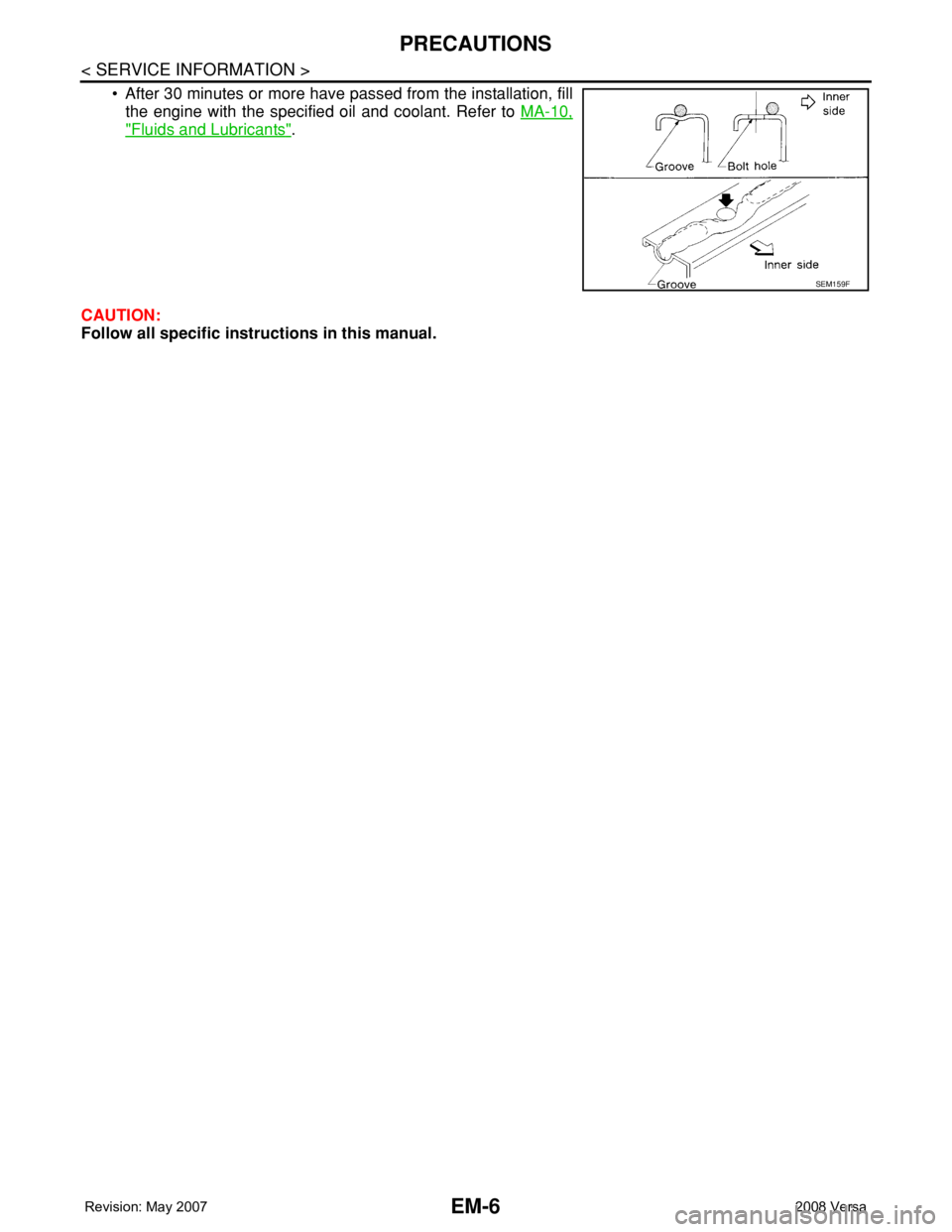
• After 30 minutes or more have passed from the installation, fill
the engine with the specified oil and coolant. Refer to MA-10,
"Fluids and Lubricants".
CAUTION:
Follow all specific instructions in this manual.
SEM159F
Page 1691 of 2771
EM-14
< SERVICE INFORMATION >
DRIVE BELTS
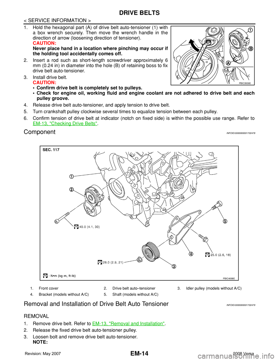
1. Hold the hexagonal part (A) of drive belt auto-tensioner (1) with
a box wrench securely. Then move the wrench handle in the
direction of arrow (loosening direction of tensioner).
CAUTION:
Never place hand in a location where pinching may occur if
the holding tool accidentally comes off.
2. Insert a rod such as short-length screwdriver approximately 6
mm (0.24 in) in diameter into the hole (B) of retaining boss to fix
drive belt auto-tensioner.
3. Install drive belt.
CAUTION:
• Confirm drive belt is completely set to pulleys.
• Check for engine oil, working fluid and engine coolant are not adhered to drive belt and each
pulley groove.
4. Release drive belt auto-tensioner, and apply tension to drive belt.
5. Turn crankshaft pulley clockwise several times to equalize tension between each pulley.
6. Confirm tension of drive belt at indicator (notch on fixed side) is within the possible use range. Refer to
EM-13, "
Checking Drive Belts".
ComponentINFOID:0000000001702478
Removal and Installation of Drive Belt Auto TensionerINFOID:0000000001702479
REMOVAL
1. Remove drive belt. Refer to EM-13, "Removal and Installation".
2. Release the fixed drive belt auto-tensioner pulley.
3. Loosen bolt and remove drive belt auto-tensioner.
NOTE:
PBIC3936E
1. Front cover 2. Drive belt auto–tensioner 3. Idler pulley (models without A/C)
4. Bracket (models without A/C) 5. Shaft (models without A/C)
PBIC4698E
Page 1695 of 2771
EM-18
< SERVICE INFORMATION >
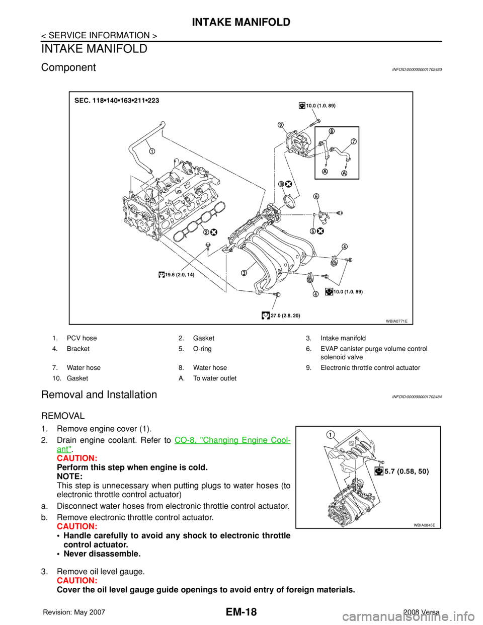
INTAKE MANIFOLD
INTAKE MANIFOLD
ComponentINFOID:0000000001702483
Removal and InstallationINFOID:0000000001702484
REMOVAL
1. Remove engine cover (1).
2. Drain engine coolant. Refer to CO-8, "
Changing Engine Cool-
ant".
CAUTION:
Perform this step when engine is cold.
NOTE:
This step is unnecessary when putting plugs to water hoses (to
electronic throttle control actuator)
a. Disconnect water hoses from electronic throttle control actuator.
b. Remove electronic throttle control actuator.
CAUTION:
• Handle carefully to avoid any shock to electronic throttle
control actuator.
• Never disassemble.
3. Remove oil level gauge.
CAUTION:
Cover the oil level gauge guide openings to avoid entry of foreign materials.
1. PCV hose 2. Gasket 3. Intake manifold
4. Bracket 5. O-ring 6. EVAP canister purge volume control
solenoid valve
7. Water hose 8. Water hose 9. Electronic throttle control actuator
10. Gasket A. To water outlet
WBIA0771E
WBIA0845E