Page 995 of 2771
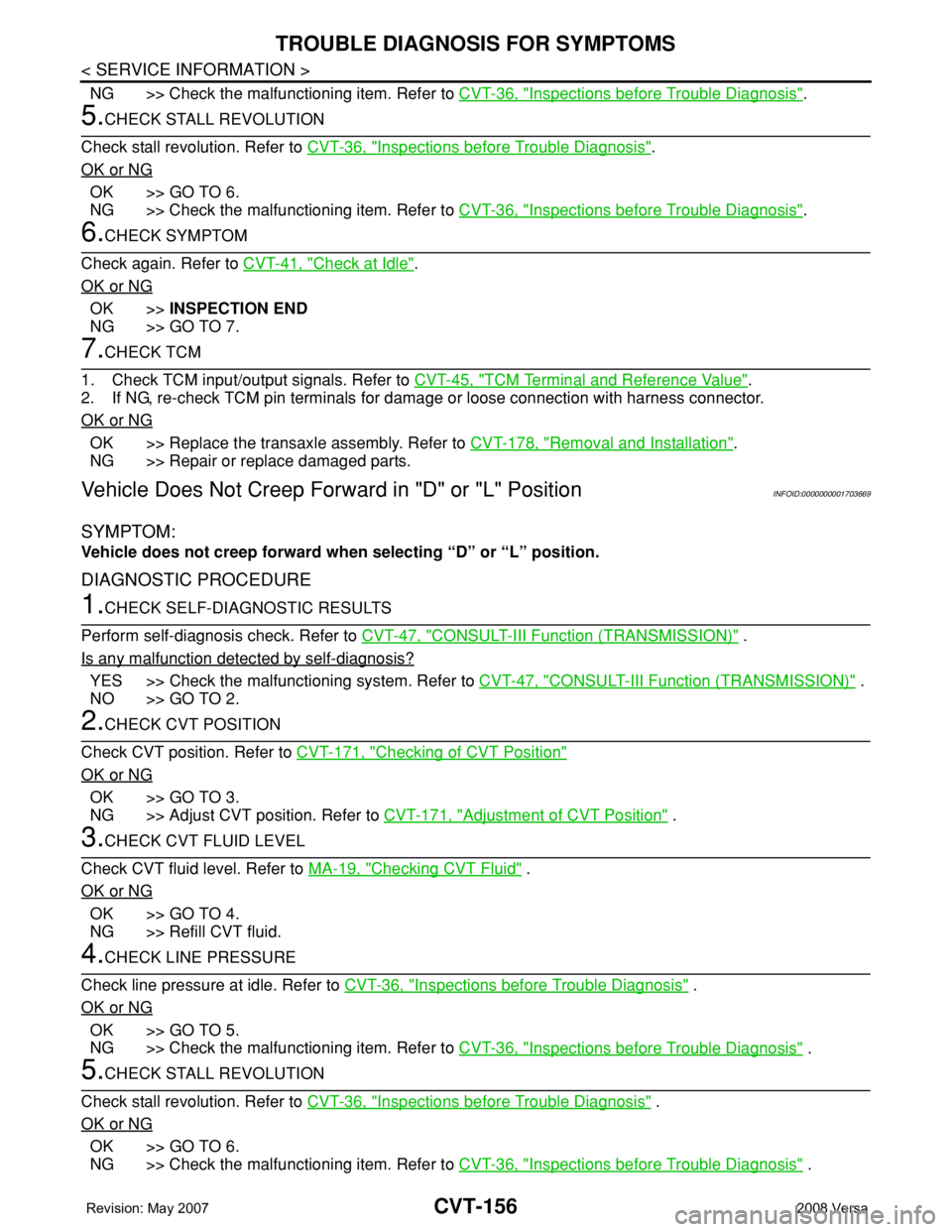
CVT-156
< SERVICE INFORMATION >
TROUBLE DIAGNOSIS FOR SYMPTOMS
NG >> Check the malfunctioning item. Refer to CVT-36, "Inspections before Trouble Diagnosis".
5.CHECK STALL REVOLUTION
Check stall revolution. Refer to CVT-36, "
Inspections before Trouble Diagnosis".
OK or NG
OK >> GO TO 6.
NG >> Check the malfunctioning item. Refer to CVT-36, "
Inspections before Trouble Diagnosis".
6.CHECK SYMPTOM
Check again. Refer to CVT-41, "
Check at Idle".
OK or NG
OK >>INSPECTION END
NG >> GO TO 7.
7.CHECK TCM
1. Check TCM input/output signals. Refer to CVT-45, "
TCM Terminal and Reference Value".
2. If NG, re-check TCM pin terminals for damage or loose connection with harness connector.
OK or NG
OK >> Replace the transaxle assembly. Refer to CVT-178, "Removal and Installation".
NG >> Repair or replace damaged parts.
Vehicle Does Not Creep Forward in "D" or "L" PositionINFOID:0000000001703669
SYMPTOM:
Vehicle does not creep forward when selecting “D” or “L” position.
DIAGNOSTIC PROCEDURE
1.CHECK SELF-DIAGNOSTIC RESULTS
Perform self-diagnosis check. Refer to CVT-47, "
CONSULT-III Function (TRANSMISSION)" .
Is any malfunction detected by self-diagnosis?
YES >> Check the malfunctioning system. Refer to CVT-47, "CONSULT-III Function (TRANSMISSION)" .
NO >> GO TO 2.
2.CHECK CVT POSITION
Check CVT position. Refer to CVT-171, "
Checking of CVT Position"
OK or NG
OK >> GO TO 3.
NG >> Adjust CVT position. Refer to CVT-171, "
Adjustment of CVT Position" .
3.CHECK CVT FLUID LEVEL
Check CVT fluid level. Refer to MA-19, "
Checking CVT Fluid" .
OK or NG
OK >> GO TO 4.
NG >> Refill CVT fluid.
4.CHECK LINE PRESSURE
Check line pressure at idle. Refer to CVT-36, "
Inspections before Trouble Diagnosis" .
OK or NG
OK >> GO TO 5.
NG >> Check the malfunctioning item. Refer to CVT-36, "
Inspections before Trouble Diagnosis" .
5.CHECK STALL REVOLUTION
Check stall revolution. Refer to CVT-36, "
Inspections before Trouble Diagnosis" .
OK or NG
OK >> GO TO 6.
NG >> Check the malfunctioning item. Refer to CVT-36, "
Inspections before Trouble Diagnosis" .
Page 996 of 2771
TROUBLE DIAGNOSIS FOR SYMPTOMS
CVT-157
< SERVICE INFORMATION >
D
E
F
G
H
I
J
K
L
MA
B
CVT
N
O
P
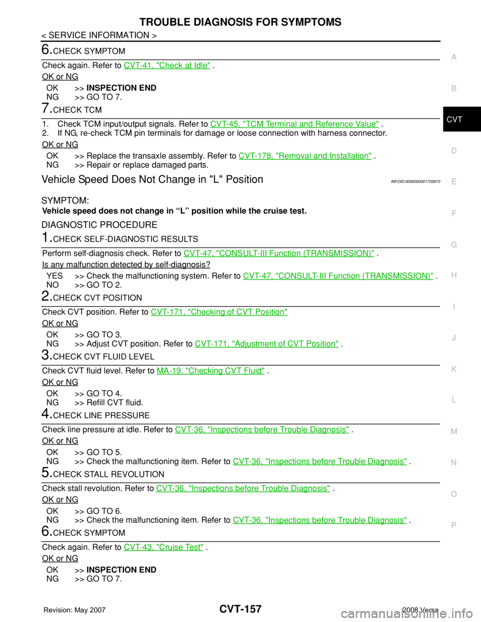
6.CHECK SYMPTOM
Check again. Refer to CVT-41, "
Check at Idle" .
OK or NG
OK >>INSPECTION END
NG >> GO TO 7.
7.CHECK TCM
1. Check TCM input/output signals. Refer to CVT-45, "
TCM Terminal and Reference Value" .
2. If NG, re-check TCM pin terminals for damage or loose connection with harness connector.
OK or NG
OK >> Replace the transaxle assembly. Refer to CVT-178, "Removal and Installation" .
NG >> Repair or replace damaged parts.
Vehicle Speed Does Not Change in "L" PositionINFOID:0000000001703670
SYMPTOM:
Vehicle speed does not change in “L” position while the cruise test.
DIAGNOSTIC PROCEDURE
1.CHECK SELF-DIAGNOSTIC RESULTS
Perform self-diagnosis check. Refer to CVT-47, "
CONSULT-III Function (TRANSMISSION)" .
Is any malfunction detected by self-diagnosis?
YES >> Check the malfunctioning system. Refer to CVT-47, "CONSULT-III Function (TRANSMISSION)" .
NO >> GO TO 2.
2.CHECK CVT POSITION
Check CVT position. Refer to CVT-171, "
Checking of CVT Position"
OK or NG
OK >> GO TO 3.
NG >> Adjust CVT position. Refer to CVT-171, "
Adjustment of CVT Position" .
3.CHECK CVT FLUID LEVEL
Check CVT fluid level. Refer to MA-19, "
Checking CVT Fluid" .
OK or NG
OK >> GO TO 4.
NG >> Refill CVT fluid.
4.CHECK LINE PRESSURE
Check line pressure at idle. Refer to CVT-36, "
Inspections before Trouble Diagnosis" .
OK or NG
OK >> GO TO 5.
NG >> Check the malfunctioning item. Refer to CVT-36, "
Inspections before Trouble Diagnosis" .
5.CHECK STALL REVOLUTION
Check stall revolution. Refer to CVT-36, "
Inspections before Trouble Diagnosis" .
OK or NG
OK >> GO TO 6.
NG >> Check the malfunctioning item. Refer to CVT-36, "
Inspections before Trouble Diagnosis" .
6.CHECK SYMPTOM
Check again. Refer to CVT-43, "
Cruise Test" .
OK or NG
OK >>INSPECTION END
NG >> GO TO 7.
Page 997 of 2771
CVT-158
< SERVICE INFORMATION >
TROUBLE DIAGNOSIS FOR SYMPTOMS
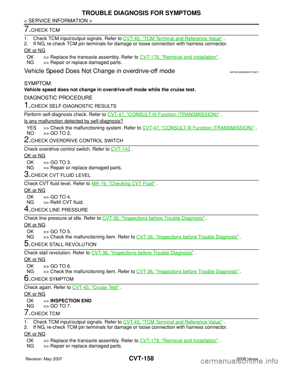
7.CHECK TCM
1. Check TCM input/output signals. Refer to CVT-45, "
TCM Terminal and Reference Value" .
2. If NG, re-check TCM pin terminals for damage or loose connection with harness connector.
OK or NG
OK >> Replace the transaxle assembly. Refer to CVT-178, "Removal and Installation" .
NG >> Repair or replace damaged parts.
Vehicle Speed Does Not Change in overdrive-off modeINFOID:0000000001703671
SYMPTOM:
Vehicle speed does not change in overdrive-off mode while the cruise test.
DIAGNOSTIC PROCEDURE
1.CHECK SELF-DIAGNOSTIC RESULTS
Perform self-diagnosis check. Refer to CVT-47, "
CONSULT-III Function (TRANSMISSION)" .
Is any malfunction detected by self-diagnosis?
YES >> Check the malfunctioning system. Refer to CVT-47, "CONSULT-III Function (TRANSMISSION)" .
NO >> GO TO 2.
2.CHECK OVERDRIVE CONTROL SWITCH
Check overdrive control switch. Refer to CVT-143
.
OK or NG
OK >> GO TO 3.
NG >> Repair or replace damaged parts.
3.CHECK CVT FLUID LEVEL
Check CVT fluid level. Refer to MA-19, "
Checking CVT Fluid" .
OK or NG
OK >> GO TO 4.
NG >> Refill CVT fluid.
4.CHECK LINE PRESSURE
Check line pressure at idle. Refer to CVT-36, "
Inspections before Trouble Diagnosis" .
OK or NG
OK >> GO TO 5.
NG >> Check the malfunctioning item. Refer to CVT-36, "
Inspections before Trouble Diagnosis" .
5.CHECK STALL REVOLUTION
Check stall revolution. Refer to CVT-36, "
Inspections before Trouble Diagnosis" .
OK or NG
OK >> GO TO 6.
NG >> Check the malfunctioning item. Refer to CVT-36, "
Inspections before Trouble Diagnosis" .
6.CHECK SYMPTOM
Check again. Refer to CVT-43, "
Cruise Test" .
OK or NG
OK >>INSPECTION END
NG >> GO TO 7.
7.CHECK TCM
1. Check TCM input/output signals. Refer to CVT-45, "
TCM Terminal and Reference Value" .
2. If NG, re-check TCM pin terminals for damage or loose connection with harness connector.
OK or NG
OK >> Replace the transaxle assembly. Refer to CVT-178, "Removal and Installation" .
NG >> Repair or replace damaged parts.
Page 998 of 2771
TROUBLE DIAGNOSIS FOR SYMPTOMS
CVT-159
< SERVICE INFORMATION >
D
E
F
G
H
I
J
K
L
MA
B
CVT
N
O
P
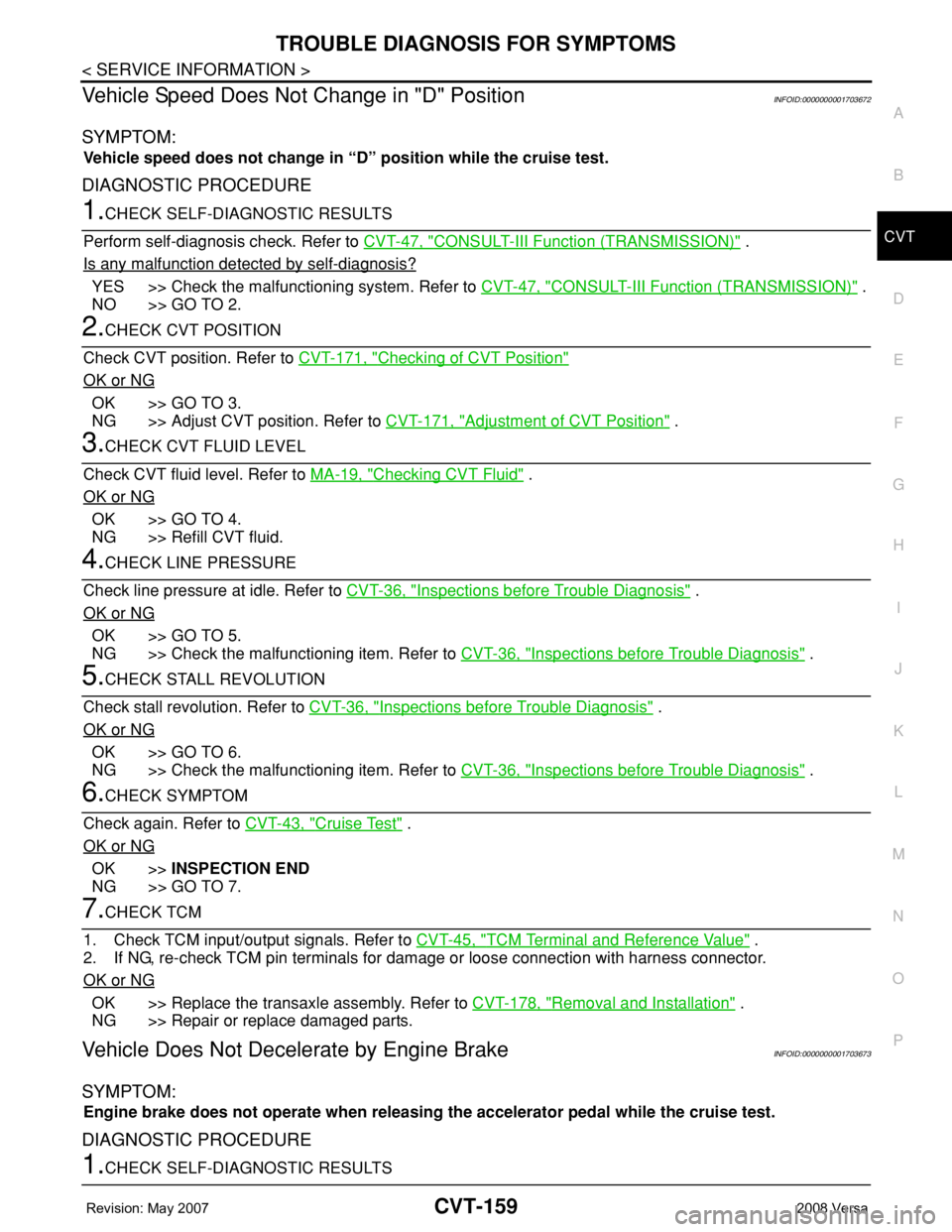
Vehicle Speed Does Not Change in "D" PositionINFOID:0000000001703672
SYMPTOM:
Vehicle speed does not change in “D” position while the cruise test.
DIAGNOSTIC PROCEDURE
1.CHECK SELF-DIAGNOSTIC RESULTS
Perform self-diagnosis check. Refer to CVT-47, "
CONSULT-III Function (TRANSMISSION)" .
Is any malfunction detected by self-diagnosis?
YES >> Check the malfunctioning system. Refer to CVT-47, "CONSULT-III Function (TRANSMISSION)" .
NO >> GO TO 2.
2.CHECK CVT POSITION
Check CVT position. Refer to CVT-171, "
Checking of CVT Position"
OK or NG
OK >> GO TO 3.
NG >> Adjust CVT position. Refer to CVT-171, "
Adjustment of CVT Position" .
3.CHECK CVT FLUID LEVEL
Check CVT fluid level. Refer to MA-19, "
Checking CVT Fluid" .
OK or NG
OK >> GO TO 4.
NG >> Refill CVT fluid.
4.CHECK LINE PRESSURE
Check line pressure at idle. Refer to CVT-36, "
Inspections before Trouble Diagnosis" .
OK or NG
OK >> GO TO 5.
NG >> Check the malfunctioning item. Refer to CVT-36, "
Inspections before Trouble Diagnosis" .
5.CHECK STALL REVOLUTION
Check stall revolution. Refer to CVT-36, "
Inspections before Trouble Diagnosis" .
OK or NG
OK >> GO TO 6.
NG >> Check the malfunctioning item. Refer to CVT-36, "
Inspections before Trouble Diagnosis" .
6.CHECK SYMPTOM
Check again. Refer to CVT-43, "
Cruise Test" .
OK or NG
OK >>INSPECTION END
NG >> GO TO 7.
7.CHECK TCM
1. Check TCM input/output signals. Refer to CVT-45, "
TCM Terminal and Reference Value" .
2. If NG, re-check TCM pin terminals for damage or loose connection with harness connector.
OK or NG
OK >> Replace the transaxle assembly. Refer to CVT-178, "Removal and Installation" .
NG >> Repair or replace damaged parts.
Vehicle Does Not Decelerate by Engine BrakeINFOID:0000000001703673
SYMPTOM:
Engine brake does not operate when releasing the accelerator pedal while the cruise test.
DIAGNOSTIC PROCEDURE
1.CHECK SELF-DIAGNOSTIC RESULTS
Page 999 of 2771
CVT-160
< SERVICE INFORMATION >
TROUBLE DIAGNOSIS FOR SYMPTOMS
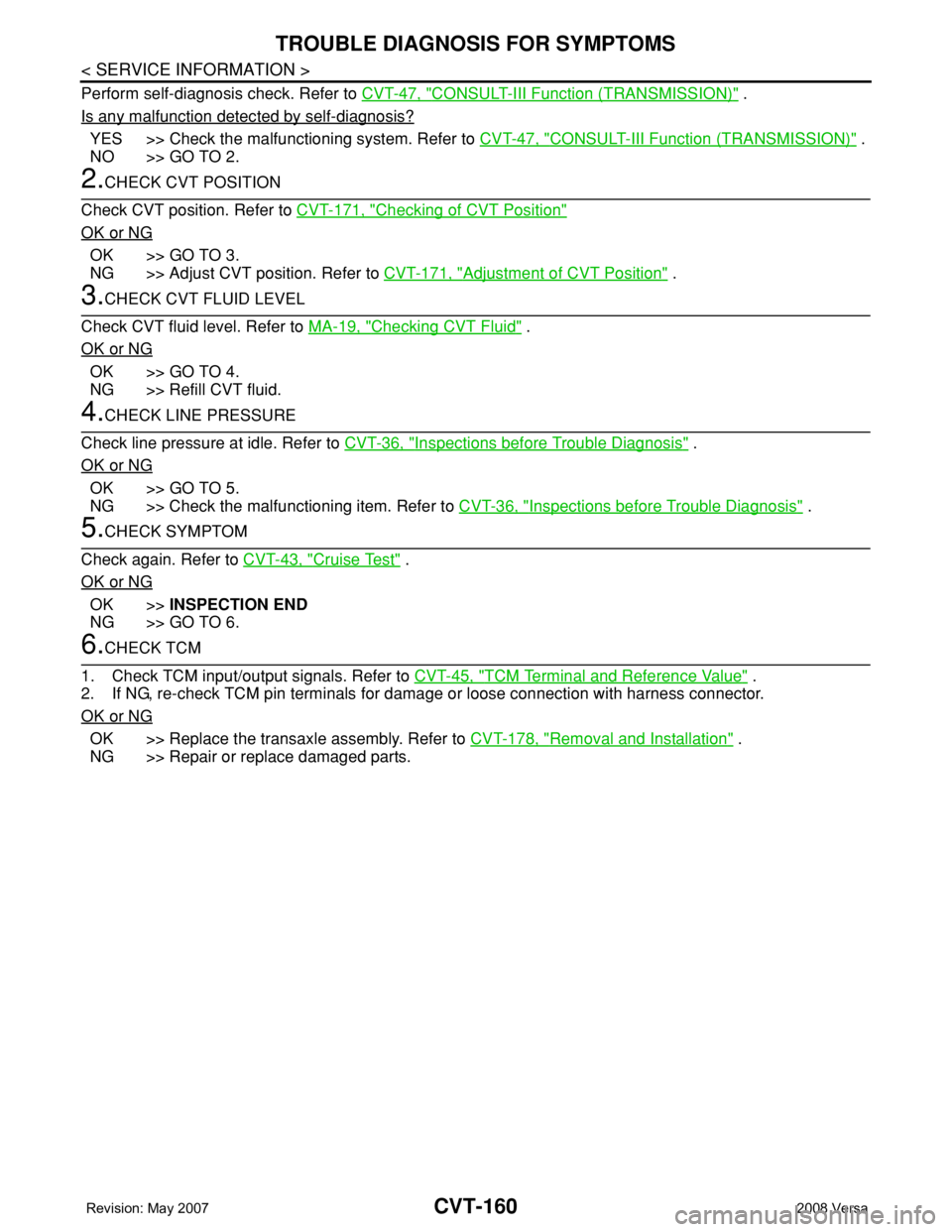
Perform self-diagnosis check. Refer to CVT-47, "CONSULT-III Function (TRANSMISSION)" .
Is any malfunction detected by self-diagnosis?
YES >> Check the malfunctioning system. Refer to CVT-47, "CONSULT-III Function (TRANSMISSION)" .
NO >> GO TO 2.
2.CHECK CVT POSITION
Check CVT position. Refer to CVT-171, "
Checking of CVT Position"
OK or NG
OK >> GO TO 3.
NG >> Adjust CVT position. Refer to CVT-171, "
Adjustment of CVT Position" .
3.CHECK CVT FLUID LEVEL
Check CVT fluid level. Refer to MA-19, "
Checking CVT Fluid" .
OK or NG
OK >> GO TO 4.
NG >> Refill CVT fluid.
4.CHECK LINE PRESSURE
Check line pressure at idle. Refer to CVT-36, "
Inspections before Trouble Diagnosis" .
OK or NG
OK >> GO TO 5.
NG >> Check the malfunctioning item. Refer to CVT-36, "
Inspections before Trouble Diagnosis" .
5.CHECK SYMPTOM
Check again. Refer to CVT-43, "
Cruise Test" .
OK or NG
OK >>INSPECTION END
NG >> GO TO 6.
6.CHECK TCM
1. Check TCM input/output signals. Refer to CVT-45, "
TCM Terminal and Reference Value" .
2. If NG, re-check TCM pin terminals for damage or loose connection with harness connector.
OK or NG
OK >> Replace the transaxle assembly. Refer to CVT-178, "Removal and Installation" .
NG >> Repair or replace damaged parts.
Page 1000 of 2771
TRANSMISSION CONTROL MODULE
CVT-161
< SERVICE INFORMATION >
D
E
F
G
H
I
J
K
L
MA
B
CVT
N
O
P
TRANSMISSION CONTROL MODULE
Removal and InstallationINFOID:0000000001703674
COMPONENTS
REMOVAL
1. Disconnect the battery negative terminal.
2. Disconnect the TCM harness connector (1) from the TCM (2).
• Instrument lower finisher (3)
3. Remove the TCM (2).
INSTALLATION
Installation is in the reverse order of removal.
1. TCM
SCIA6963E
SCIA7167E
Page 1001 of 2771
CVT-162
< SERVICE INFORMATION >
CVT SHIFT LOCK SYSTEM
CVT SHIFT LOCK SYSTEM
DescriptionINFOID:0000000001703675
• The mechanical key interlock mechanism also operates as a shift lock:
With the ignition switch turned to ON, selector lever cannot be shifted from “P” position to any other position
unless brake pedal is depressed.
With the key removed, selector lever cannot be shifted from “P” position to any other position.
The key cannot be removed unless selector lever is placed in “P” position.
• The shift lock and key interlock mechanisms are controlled by the ON-OFF operation of the shift lock sole-
noid and by the operation of the rotator and slider located inside key cylinder, respectively.
Shift Lock System Electrical Parts LocationINFOID:0000000001703676
1. Key interlock cable 2. Key cylinder 3. Stop lamp switch
4. Brake pedal 5. Shift lock release button 6. Key interlock cable
7. Shift lock solenoid 8. Park position switch
BCIA0034E
Page 1002 of 2771
CVT SHIFT LOCK SYSTEM
CVT-163
< SERVICE INFORMATION >
D
E
F
G
H
I
J
K
L
MA
B
CVT
N
O
P
Wiring Diagram - CVT - SHIFTINFOID:0000000001703677
Diagnosis ProcedureINFOID:0000000001703678
SYMPTOM 1:
•Selector lever cannot be moved from “P” position with ignition switch in ON position and brake
pedal depressed.
BCWA0685E