Page 987 of 2771

CVT-148
< SERVICE INFORMATION >
SHIFT POSITION INDICATOR CIRCUIT
SHIFT POSITION INDICATOR CIRCUIT
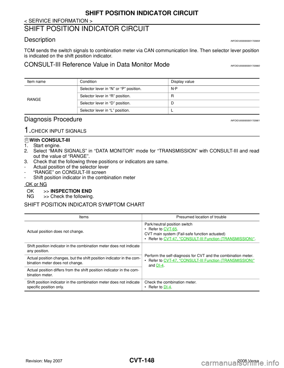
DescriptionINFOID:0000000001703659
TCM sends the switch signals to combination meter via CAN communication line. Then selector lever position
is indicated on the shift position indicator.
CONSULT-III Reference Value in Data Monitor ModeINFOID:0000000001703660
Diagnosis ProcedureINFOID:0000000001703661
1.CHECK INPUT SIGNALS
With CONSULT-III
1. Start engine.
2. Select “MAIN SIGNALS” in “DATA MONITOR” mode for “TRANSMISSION” with CONSULT-III and read
out the value of “RANGE”.
3. Check that the following three positions or indicators are same.
- Actual position of the selector lever
- “RANGE” on CONSULT-III screen
- Shift position indicator in the combination meter
OK or NG
OK >>INSPECTION END
NG >> Check the following.
SHIFT POSITION INDICATOR SYMPTOM CHART
Item name Condition Display value
RANGESelector lever in “N” or “P” position. N·P
Selector lever in “R” position. R
Selector lever in “D” position. D
Selector lever in “L” position. L
Items Presumed location of trouble
Actual position does not change.Park/neutral position switch
• Refer to CVT-65
.
CVT main system (Fail-safe function actuated)
• Refer to CVT-47, "
CONSULT-III Function (TRANSMISSION)".
Shift position indicator in the combination meter does not indicate
any position.
Perform the self-diagnosis for CVT and the combination meter.
• Refer to CVT-47, "
CONSULT-III Function (TRANSMISSION)"
and DI-4
. Actual position changes, but the shift position indicator in the com-
bination meter does not change.
Actual position differs from the shift position indicator in the com-
bination meter.
Shift position indicator in the combination meter does not indicate
specific position only.Check the combination meter.
• Refer to DI-4
.
Page 988 of 2771
TROUBLE DIAGNOSIS FOR SYMPTOMS
CVT-149
< SERVICE INFORMATION >
D
E
F
G
H
I
J
K
L
MA
B
CVT
N
O
P
TROUBLE DIAGNOSIS FOR SYMPTOMS
Wiring Diagram - CVT - NONDTCINFOID:0000000001703662
BCWA0682E
Page 989 of 2771
CVT-150
< SERVICE INFORMATION >
TROUBLE DIAGNOSIS FOR SYMPTOMS
BCWA0683E
Page 990 of 2771
TROUBLE DIAGNOSIS FOR SYMPTOMS
CVT-151
< SERVICE INFORMATION >
D
E
F
G
H
I
J
K
L
MA
B
CVT
N
O
P
TCM TERMINALS AND REFERENCE VALUES
Refer to CVT-45, "TCM Terminal and Reference Value".
O/D OFF Indicator Lamp Does Not Come OnINFOID:0000000001703663
SYMPTOM:
BCWA0684E
Page 991 of 2771

CVT-152
< SERVICE INFORMATION >
TROUBLE DIAGNOSIS FOR SYMPTOMS
O/D OFF indicator lamp does not come on for about 2 seconds when turning ignition switch ON.
DIAGNOSTIC PROCEDURE
1.CHECK CAN COMMUNICATION LINE
Perform the self-diagnosis check. Refer to CVT-47, "
CONSULT-III Function (TRANSMISSION)".
Is any malfunction of the
“U1000 CAN COMM CIRCUIT” indicated in the results?
YES >> Check CAN communication line. Refer to CVT-56.
NO >> GO TO 2.
2.CHECK TCM POWER SOURCE
1. Turn ignition switch ON.
2. Check voltage between TCM connector terminals and ground.
Refer to CVT-122, "
Wiring Diagram - CVT - POWER".
OK or NG
OK >> GO TO 4.
NG >> GO TO 3.
3.DETECT MALFUNCTIONING ITEM
Check the following.
• Harness for short or open between ignition switch and TCM connector terminal 10, 19
Refer to CVT-122, "
Wiring Diagram - CVT - POWER".
• 10 A fuse (No.49, located in the IPDM E/R). Refer to CVT-122, "
Wiring Diagram - CVT - POWER".
• Ignition switch. Refer to PG-3
.
OK or NG
OK >> GO TO 4.
NG >> Repair or replace damaged parts.
4.CHECK TCM GROUND CIRCUIT
1. Turn ignition switch OFF.
2. Disconnect TCM connector.
3. Check continuity between TCM connector terminals and ground.
Refer to CVT-122, "
Wiring Diagram - CVT - POWER".
OK or NG
OK >> GO TO 5.
NG >> Repair open circuit or short to ground or short to power
in harness or connectors.
5.DETECT MALFUNCTIONING ITEM
Check the following.
• Harness and fuse for short or open between ignition switch and O/D OFF indicator lamp
Refer to PG-3
.
OK or NG
OK >> GO TO 6.
NG >> Repair or replace damaged parts.
6.CHECK SYMPTOM
NameConnec-
torTerminal Voltage (Approx.)
Power supply E3110 Battery voltage
19 Battery voltage
SCIA4737E
NameConnec-
torTerminal Continuity
Ground E3225
Ye s
48
SCIA2671E
Page 992 of 2771

TROUBLE DIAGNOSIS FOR SYMPTOMS
CVT-153
< SERVICE INFORMATION >
D
E
F
G
H
I
J
K
L
MA
B
CVT
N
O
P
Check again. Refer to CVT-41, "Check before Engine Is Started".
OK or NG
OK >>INSPECTION END
NG >> GO TO 7.
7.CHECK COMBINATION METERS
Check combination meters. Refer to DI-4
OK or NG
OK >>INSPECTION END
NG >> Repair or replace damaged parts.
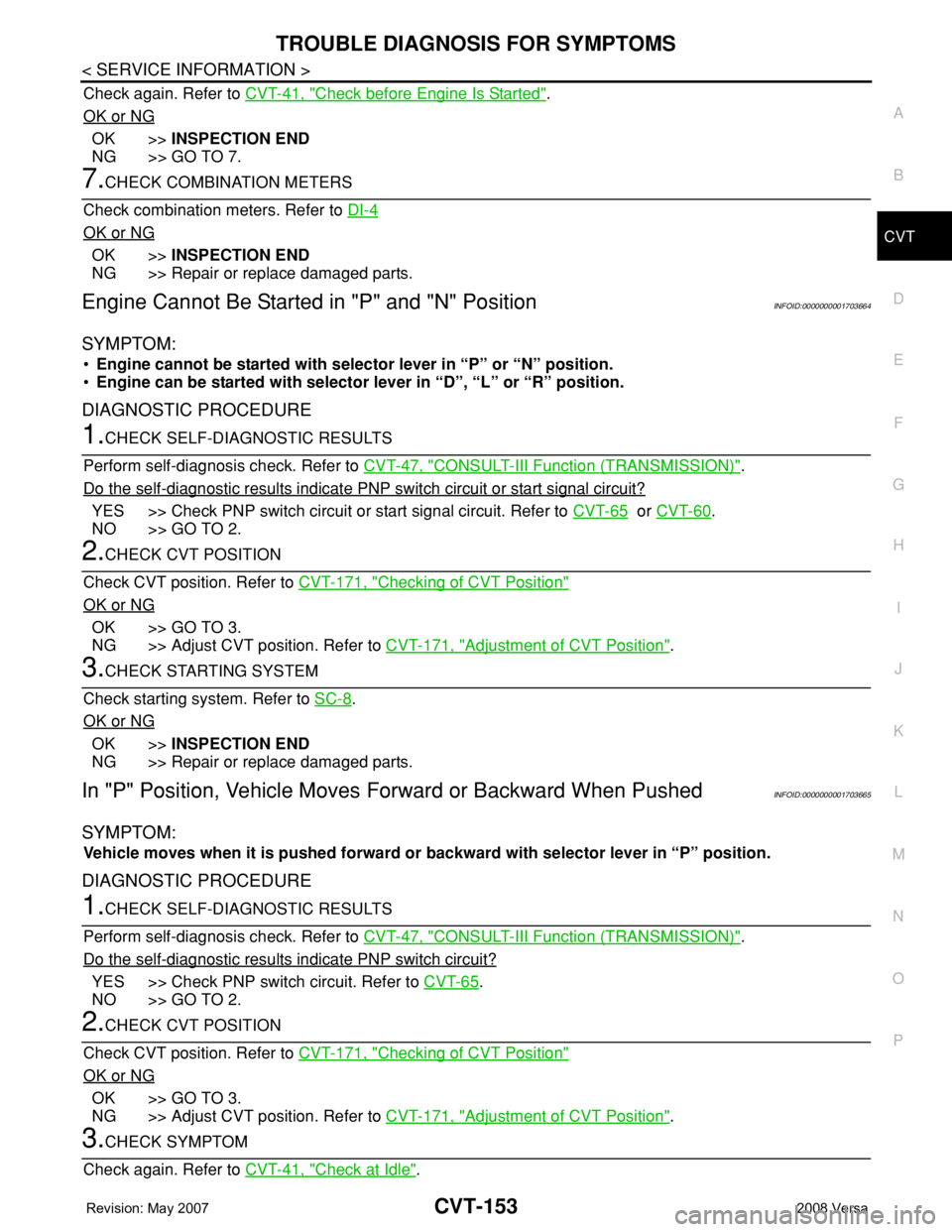
Engine Cannot Be Started in "P" and "N" PositionINFOID:0000000001703664
SYMPTOM:
•Engine cannot be started with selector lever in “P” or “N” position.
•Engine can be started with selector lever in “D”, “L” or “R” position.
DIAGNOSTIC PROCEDURE
1.CHECK SELF-DIAGNOSTIC RESULTS
Perform self-diagnosis check. Refer to CVT-47, "
CONSULT-III Function (TRANSMISSION)".
Do the self-diagnostic results indicate PNP switch circuit or start signal circuit?
YES >> Check PNP switch circuit or start signal circuit. Refer to CVT-65 or CVT-60.
NO >> GO TO 2.
2.CHECK CVT POSITION
Check CVT position. Refer to CVT-171, "
Checking of CVT Position"
OK or NG
OK >> GO TO 3.
NG >> Adjust CVT position. Refer to CVT-171, "
Adjustment of CVT Position".
3.CHECK STARTING SYSTEM
Check starting system. Refer to SC-8
.
OK or NG
OK >>INSPECTION END
NG >> Repair or replace damaged parts.
In "P" Position, Vehicle Moves Forward or Backward When PushedINFOID:0000000001703665
SYMPTOM:
Vehicle moves when it is pushed forward or backward with selector lever in “P” position.
DIAGNOSTIC PROCEDURE
1.CHECK SELF-DIAGNOSTIC RESULTS
Perform self-diagnosis check. Refer to CVT-47, "
CONSULT-III Function (TRANSMISSION)".
Do the self-diagnostic results indicate PNP switch circuit?
YES >> Check PNP switch circuit. Refer to CVT-65.
NO >> GO TO 2.
2.CHECK CVT POSITION
Check CVT position. Refer to CVT-171, "
Checking of CVT Position"
OK or NG
OK >> GO TO 3.
NG >> Adjust CVT position. Refer to CVT-171, "
Adjustment of CVT Position".
3.CHECK SYMPTOM
Check again. Refer to CVT-41, "
Check at Idle".
Page 993 of 2771

CVT-154
< SERVICE INFORMATION >
TROUBLE DIAGNOSIS FOR SYMPTOMS
OK or NG
OK >>INSPECTION END
NG >> Replace the transaxle assembly. Refer to CVT-178, "
Removal and Installation".
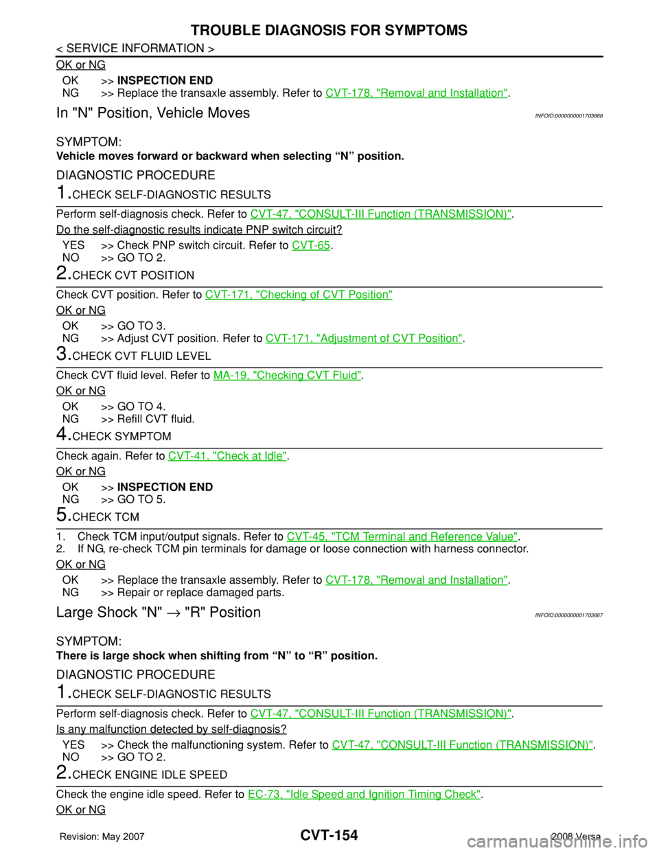
In "N" Position, Vehicle MovesINFOID:0000000001703666
SYMPTOM:
Vehicle moves forward or backward when selecting “N” position.
DIAGNOSTIC PROCEDURE
1.CHECK SELF-DIAGNOSTIC RESULTS
Perform self-diagnosis check. Refer to CVT-47, "
CONSULT-III Function (TRANSMISSION)".
Do the self-diagnostic results indicate PNP switch circuit?
YES >> Check PNP switch circuit. Refer to CVT-65.
NO >> GO TO 2.
2.CHECK CVT POSITION
Check CVT position. Refer to CVT-171, "
Checking of CVT Position"
OK or NG
OK >> GO TO 3.
NG >> Adjust CVT position. Refer to CVT-171, "
Adjustment of CVT Position".
3.CHECK CVT FLUID LEVEL
Check CVT fluid level. Refer to MA-19, "
Checking CVT Fluid".
OK or NG
OK >> GO TO 4.
NG >> Refill CVT fluid.
4.CHECK SYMPTOM
Check again. Refer to CVT-41, "
Check at Idle".
OK or NG
OK >>INSPECTION END
NG >> GO TO 5.
5.CHECK TCM
1. Check TCM input/output signals. Refer to CVT-45, "
TCM Terminal and Reference Value".
2. If NG, re-check TCM pin terminals for damage or loose connection with harness connector.
OK or NG
OK >> Replace the transaxle assembly. Refer to CVT-178, "Removal and Installation".
NG >> Repair or replace damaged parts.
Large Shock "N" → "R" PositionINFOID:0000000001703667
SYMPTOM:
There is large shock when shifting from “N” to “R” position.
DIAGNOSTIC PROCEDURE
1.CHECK SELF-DIAGNOSTIC RESULTS
Perform self-diagnosis check. Refer to CVT-47, "
CONSULT-III Function (TRANSMISSION)".
Is any malfunction detected by self-diagnosis?
YES >> Check the malfunctioning system. Refer to CVT-47, "CONSULT-III Function (TRANSMISSION)".
NO >> GO TO 2.
2.CHECK ENGINE IDLE SPEED
Check the engine idle speed. Refer to EC-73, "
Idle Speed and Ignition Timing Check".
OK or NG
Page 994 of 2771

TROUBLE DIAGNOSIS FOR SYMPTOMS
CVT-155
< SERVICE INFORMATION >
D
E
F
G
H
I
J
K
L
MA
B
CVT
N
O
P
OK >> GO TO 3.
NG >> Repair.
3.CHECK CVT FLUID LEVEL
Check CVT fluid level. Refer to MA-19, "
Checking CVT Fluid".
OK or NG
OK >> GO TO 4.
NG >> Refill CVT fluid.
4.CHECK LINE PRESSURE
Check line pressure at idle. Refer to CVT-36, "
Inspections before Trouble Diagnosis".
OK or NG
OK >> GO TO 5.
NG >> Check the malfunctioning item. Refer to CVT-36, "
Inspections before Trouble Diagnosis".
5.SYMPTOM CHECK
Check again. Refer to CVT-41, "
Check at Idle".
OK or NG
OK >>INSPECTION END
NG >> GO TO 6.
6.CHECK TCM
1. Check TCM input/output signals. Refer to CVT-45, "
TCM Terminal and Reference Value".
2. If NG, re-check TCM pin terminals for damage or loose connection with harness connector.
OK or NG
OK >> Replace the transaxle assembly. Refer to CVT-178, "Removal and Installation".
NG >> Repair or replace damaged parts.
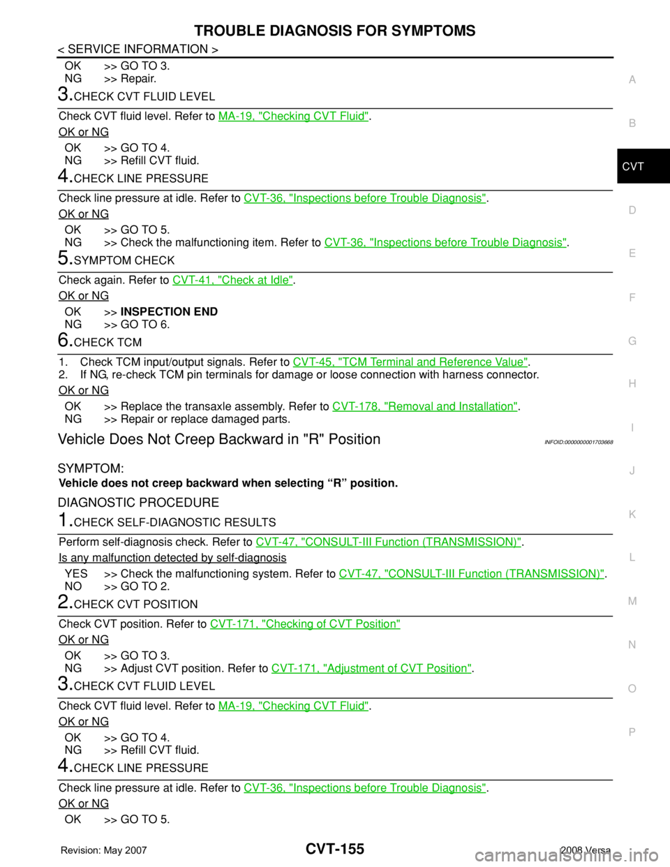
Vehicle Does Not Creep Backward in "R" PositionINFOID:0000000001703668
SYMPTOM:
Vehicle does not creep backward when selecting “R” position.
DIAGNOSTIC PROCEDURE
1.CHECK SELF-DIAGNOSTIC RESULTS
Perform self-diagnosis check. Refer to CVT-47, "
CONSULT-III Function (TRANSMISSION)".
Is any malfunction detected by self-diagnosis
YES >> Check the malfunctioning system. Refer to CVT-47, "CONSULT-III Function (TRANSMISSION)".
NO >> GO TO 2.
2.CHECK CVT POSITION
Check CVT position. Refer to CVT-171, "
Checking of CVT Position"
OK or NG
OK >> GO TO 3.
NG >> Adjust CVT position. Refer to CVT-171, "
Adjustment of CVT Position".
3.CHECK CVT FLUID LEVEL
Check CVT fluid level. Refer to MA-19, "
Checking CVT Fluid".
OK or NG
OK >> GO TO 4.
NG >> Refill CVT fluid.
4.CHECK LINE PRESSURE
Check line pressure at idle. Refer to CVT-36, "
Inspections before Trouble Diagnosis".
OK or NG
OK >> GO TO 5.