2008 NISSAN LATIO sensor
[x] Cancel search: sensorPage 280 of 2771
AT-268
< SERVICE INFORMATION >
REPAIR FOR COMPONENT PARTS
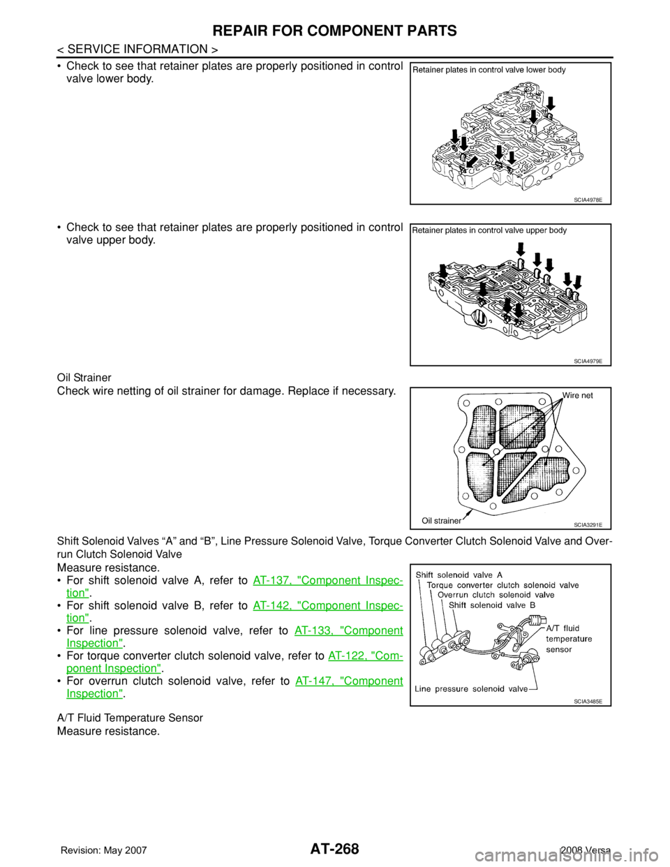
• Check to see that retainer plates are properly positioned in control
valve lower body.
• Check to see that retainer plates are properly positioned in control
valve upper body.
Oil Strainer
Check wire netting of oil strainer for damage. Replace if necessary.
Shift Solenoid Valves “A” and “B”, Line Pressure Solenoid Valve, Torque Converter Clutch Solenoid Valve and Over-
run Clutch Solenoid Valve
Measure resistance.
• For shift solenoid valve A, refer to AT-137, "
Component Inspec-
tion".
• For shift solenoid valve B, refer to AT-142, "
Component Inspec-
tion".
• For line pressure solenoid valve, refer to AT-133, "
Component
Inspection".
• For torque converter clutch solenoid valve, refer to AT-122, "
Com-
ponent Inspection".
• For overrun clutch solenoid valve, refer to AT-147, "
Component
Inspection".
A/T Fluid Temperature Sensor
Measure resistance.
SCIA4978E
SCIA4979E
SCIA3291E
SCIA3485E
Page 281 of 2771
REPAIR FOR COMPONENT PARTS
AT-269
< SERVICE INFORMATION >
D
E
F
G
H
I
J
K
L
MA
B
AT
N
O
P
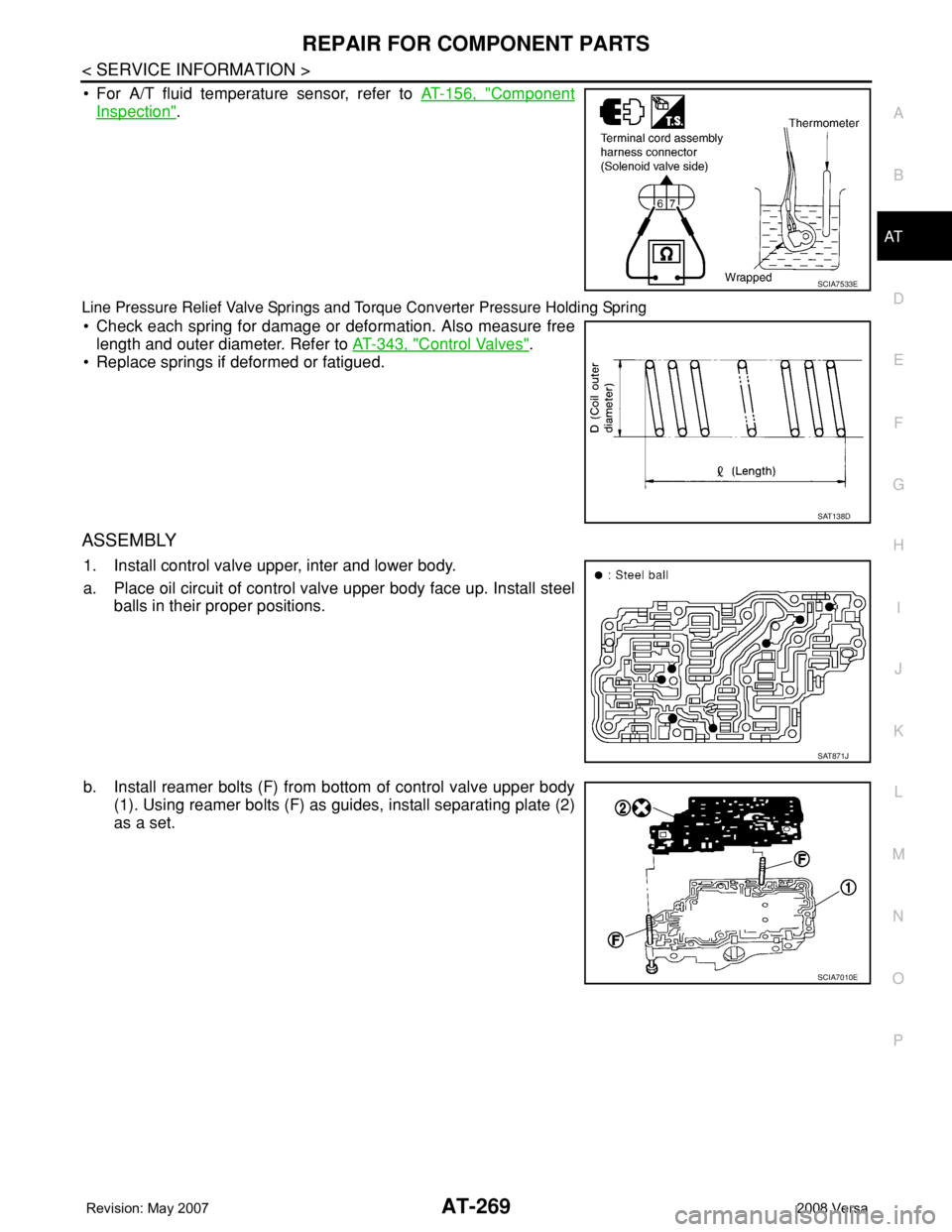
• For A/T fluid temperature sensor, refer to AT-156, "Component
Inspection".
Line Pressure Relief Valve Springs and Torque Converter Pressure Holding Spring
• Check each spring for damage or deformation. Also measure free
length and outer diameter. Refer to AT-343, "
Control Valves".
• Replace springs if deformed or fatigued.
ASSEMBLY
1. Install control valve upper, inter and lower body.
a. Place oil circuit of control valve upper body face up. Install steel
balls in their proper positions.
b. Install reamer bolts (F) from bottom of control valve upper body
(1). Using reamer bolts (F) as guides, install separating plate (2)
as a set.
SCIA7533E
SAT138D
SAT871J
SCIA7010E
Page 351 of 2771

ASSEMBLY
AT-339
< SERVICE INFORMATION >
D
E
F
G
H
I
J
K
L
MA
B
AT
N
O
P
b. Install oil pan gasket on transaxle case.
CAUTION:
• Completely remove all moisture, oil and old gasket, etc.
from the oil pan gasket mounting surface of transaxle
case.
• Do not reuse oil pan gasket.
c. Install oil pan on transaxle case.
CAUTION:
Completely remove all moisture, oil and old gasket, etc.
from the oil pan gasket mounting surface of oil pan.
d. Tighten oil pan fitting bolts (1) to the specified torque. Refer to
AT-230, "
Component".
CAUTION:
• Always replace oil pan fitting bolts (1) as they are self-sealing bolts.
• Tighten four bolts in a criss-cross pattern to prevent dislocation of gasket.
e. Install drain plug gasket and drain plug (2) to oil pan.
CAUTION:
Do not reuse drain plug gasket.
f. Tighten drain plug to the specified torque. Refer to AT-230, "
Component".
29. Install PNP switch (2) on transaxle case.
: Bolt (3)
a. Set manual shaft (1) in “P” position.
b. Temporarily install PNP switch (2) on manual shaft (1).
c. Set manual shaft (1) in “N” position.
d. Use a 4 mm (0.16 in) dia. pin for this adjustment.
i. Insert the pin straight into the manual shaft (1) adjustment hole.
ii. Rotate PNP switch (2) until the pin can also be inserted straight
into hole in PNP switch (2).
e. Tighten PNP switch fitting bolts to the specified torque. Refer to
AT-230, "
Component".
f. Remove pin from adjustment hole after adjusting PNP switch (2).
30. Install O-ring (3) to turbine revolution sensor (power train revolu-
tion sensor) (1).
31. Install turbine revolution sensor (power train revolution sensor)
(1) to transaxle case (2).
: Bolt (1)
32. Tighten turbine revolution sensor (power train revolution sensor)
fitting bolt to the specified torque. Refer to AT-230, "
Compo-
nent".
33. Install revolution sensor (1) to transaxle case (2).
34. Tighten revolution sensor fitting bolts to the specified torque.
Refer to AT-230, "
Component".
: Bolt (2)
CAUTION:
SCIA8016E
SCIA5904J
SCIA7004J
SCIA7170J
Page 352 of 2771
AT-340
< SERVICE INFORMATION >
ASSEMBLY
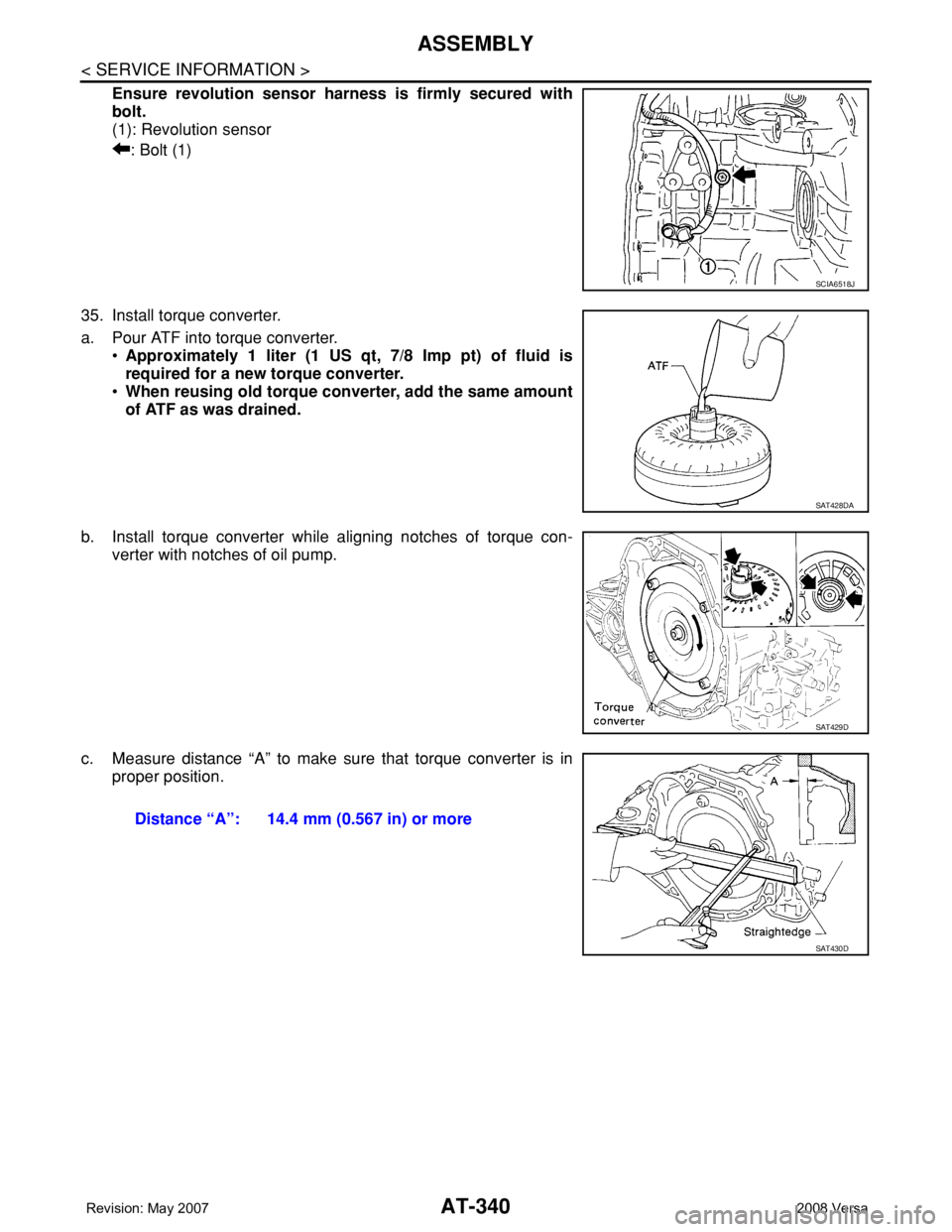
Ensure revolution sensor harness is firmly secured with
bolt.
(1): Revolution sensor
: Bolt (1)
35. Install torque converter.
a. Pour ATF into torque converter.
•Approximately 1 liter (1 US qt, 7/8 Imp pt) of fluid is
required for a new torque converter.
•When reusing old torque converter, add the same amount
of ATF as was drained.
b. Install torque converter while aligning notches of torque con-
verter with notches of oil pump.
c. Measure distance “A” to make sure that torque converter is in
proper position.
SCIA6518J
SAT428DA
SAT429D
Distance “A”: 14.4 mm (0.567 in) or more
SAT430D
Page 359 of 2771
SERVICE DATA AND SPECIFICATIONS (SDS)
AT-347
< SERVICE INFORMATION >
D
E
F
G
H
I
J
K
L
MA
B
AT
N
O
P
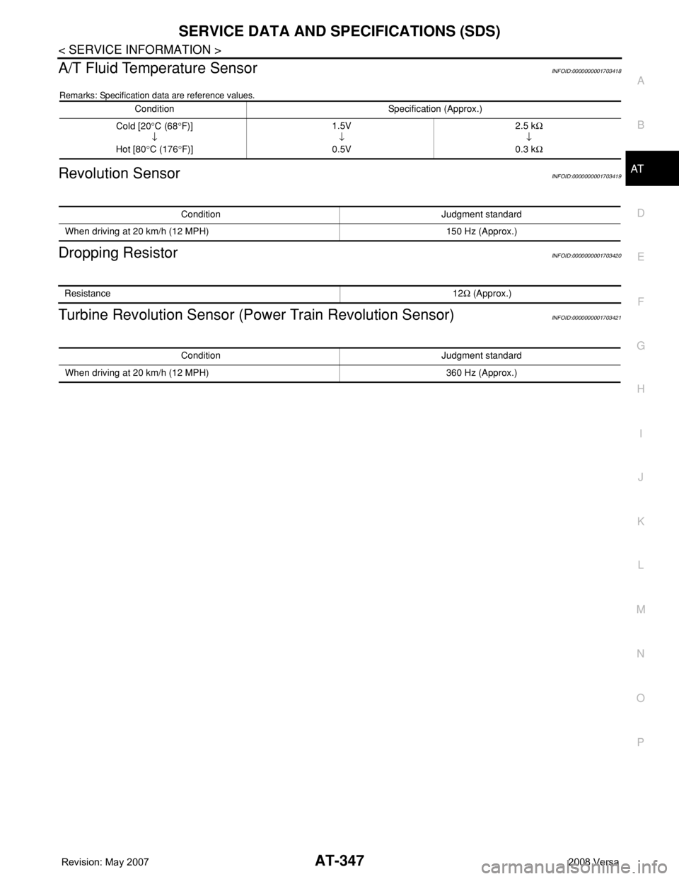
A/T Fluid Temperature SensorINFOID:0000000001703418
Remarks: Specification data are reference values.
Revolution SensorINFOID:0000000001703419
Dropping ResistorINFOID:0000000001703420
Turbine Revolution Sensor (Power Train Revolution Sensor)INFOID:0000000001703421
Condition Specification (Approx.)
Cold [20°C (68°F)]
↓
Hot [80°C (176°F)]1.5V
↓
0.5V2.5 kΩ
↓
0.3 kΩ
Condition Judgment standard
When driving at 20 km/h (12 MPH) 150 Hz (Approx.)
Resistance12Ω (Approx.)
Condition Judgment standard
When driving at 20 km/h (12 MPH) 360 Hz (Approx.)
Page 436 of 2771

BL-2
ID Code Entry Procedure .......................................71
Keyfob Battery Replacement ..................................73
Removal and Installation of Remote Keyless Entry
Receiver .................................................................
73
INTELLIGENT KEY SYSTEM ............................74
Component Parts and Harness Connector Loca-
tion ..........................................................................
74
System Description .................................................76
CAN Communication System Description ..............83
Schematic ...............................................................84
Wiring Diagram - I/KEY - ........................................86
Intelligent Key Unit Harness Connector Terminal
Layout .....................................................................
96
Terminal and Reference Value for Intelligent Key
Unit .........................................................................
96
Steering Lock Solenoid Harness Connector Ter-
minal Layout ...........................................................
98
Terminal and Reference Value for Steering Lock
Solenoid ..................................................................
98
Terminal and Reference Value for BCM .................99
Trouble Diagnosis Procedure .................................99
CONSULT-III Functions (INTELLIGENT KEY) ......100
CONSULT-III Application Item ...............................101
Trouble Diagnosis Symptom Chart ........................103
CAN Communication System Inspection ...............109
Power Supply and Ground Circuit Inspection ........110
Key Switch (Intelligent Key Unit Input) Check .......110
Key Switch (BCM Input) Check .............................112
Ignition Knob Switch Check ...................................113
Door Switch Check (Hatchback) ............................114
Door Switch Check (Sedan) ..................................117
Door Request Switch Check ..................................118
Back Door Request Switch Check (Hatchback) ....120
Trunk Opener Request Switch Check (Sedan) .....122
Unlock Sensor Check ............................................124
Intelligent Key Warning Buzzer(s) Check ..............125
Outside Key Antenna (Driver Side and Passenger
Side) Check ...........................................................
126
Outside Key Antenna (Rear Bumper) Check .........128
Inside Key Antenna Check ....................................129
Steering Lock Solenoid Check ..............................131
Key Interlock Solenoid (With M/T) Check ..............133
Ignition Switch Position Check ..............................134
Stop Lamp Switch Check (With CVT) ....................134
Stop Lamp Switch Check (With M/T) .....................135
Check CVT Device (Park Position Switch) Check ..136
"P-SHIFT" Warning Lamp (With CVT) Check ........138
"LOCK" Warning Lamp (With M/T) Check .............138
"KEY" Warning Lamp (RED) Check ......................139
"KEY" Warning Lamp (GREEN) Check .................139
Check Warning Chime in Combination Meter ........140
Hazard Function Check .........................................140
Horn Function Check .............................................140
Headlamp Function Check ....................................141
Intelligent Key Battery Replacement .....................142
Remote Keyless Entry Function ............................142
Removal and Installation of Intelligent Key Unit ....142
DOOR ...............................................................144
Fitting Adjustment .................................................144
Removal and Installation .......................................147
FRONT DOOR LOCK .......................................150
Component Parts Location ...................................150
Removal and Installation .......................................150
REAR DOOR LOCK .........................................153
Component Parts Location ...................................153
Removal and Installation .......................................153
BACK DOOR LOCK .........................................156
Component Parts and Harness Connector Loca-
tion ........................................................................
156
System Description ...............................................156
Wiring Diagram - B/DOOR - ..................................157
Terminal and Reference Value for BCM ...............158
Terminal and Reference Value for Intelligent Key
Unit ........................................................................
158
CONSULT-III Function (BCM) ..............................159
Work Flow .............................................................159
Trouble Diagnosis Chart by Symptom ..................159
BCM Power Supply and Ground Circuit ................160
Check Back Door Opener Switch Circuit (Without
Intelligent Key or Power Windows) .......................
160
Check Back Door Opener Switch Circuit (Without
Intelligent Key, with Power Windows) ...................
162
Check Back Door Opener Switch Circuit (With In-
telligent Key) .........................................................
165
Check Back Door Lock Assembly (Actuator) Cir-
cuit ........................................................................
166
Removal and Installation .......................................168
TRUNK LID .......................................................170
Fitting Adjustment .................................................170
Trunk Lid Assembly ..............................................170
Trunk Lid Lock ......................................................171
Trunk Lid Striker ....................................................171
TRUNK LID OPENER .......................................173
Component Parts and Harness Connector Loca-
tion ........................................................................
173
System Description ...............................................173
Wiring Diagram - TLID - ........................................174
Terminal and Reference Value for BCM ...............175
Terminal and Reference Value for Intelligent Key
Unit ........................................................................
175
CONSULT-III Function (BCM) ..............................176
Work Flow .............................................................176
Trouble Diagnosis Chart by Symptom ..................176
BCM Power Supply and Ground Circuit ................177
Check Trunk Lid Opener Switch Circuit (Without
Intelligent Key or Power Windows) .......................
177
Check Trunk Lid Opener Switch Circuit (Without
Intelligent Key, with Power Windows) ...................
179
Check Trunk Lid Opener Switch Circuit (With Intel-
ligent Key) .............................................................
182
Check Trunk Release Solenoid Circuit .................183
Page 450 of 2771
BL-16
< SERVICE INFORMATION >
HOOD
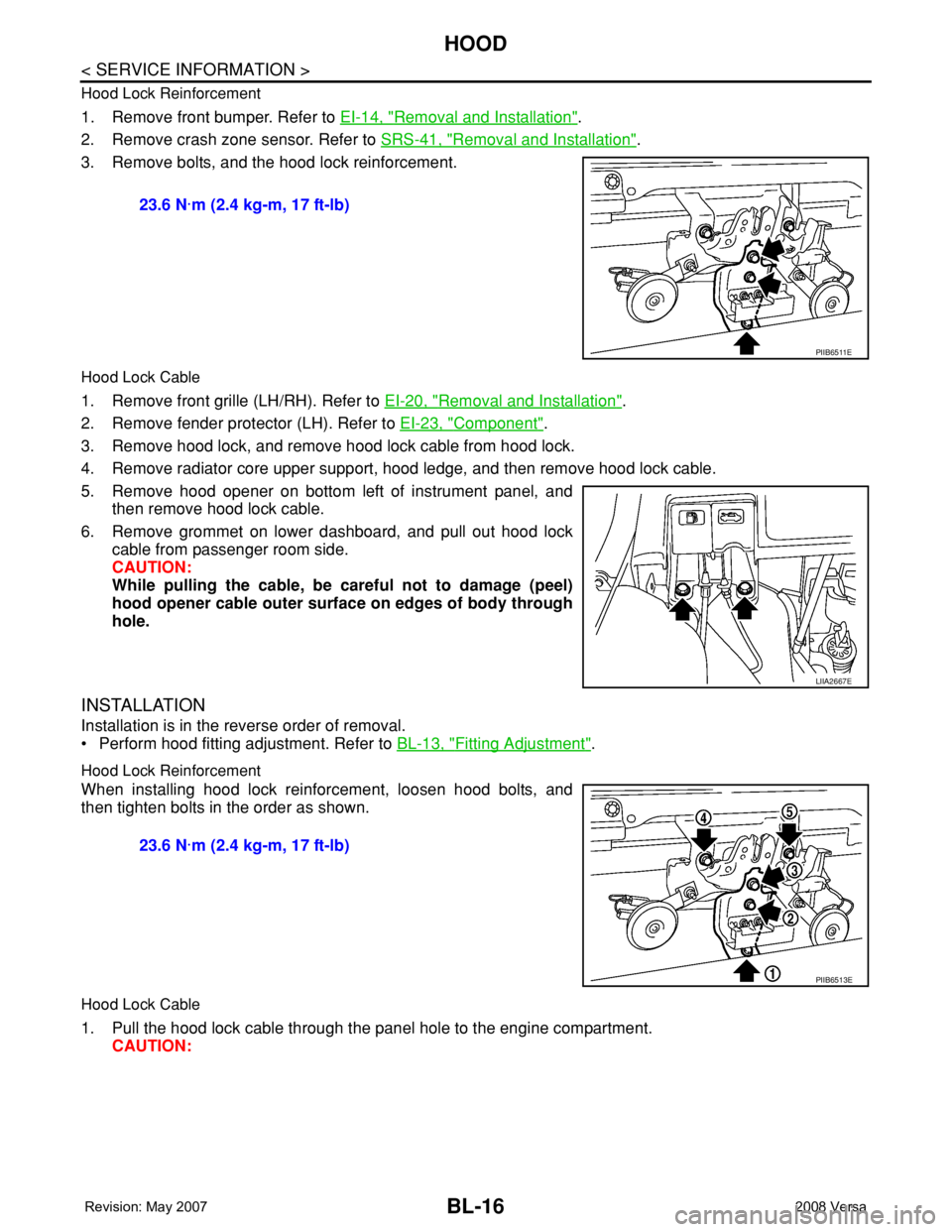
Hood Lock Reinforcement
1. Remove front bumper. Refer to EI-14, "Removal and Installation".
2. Remove crash zone sensor. Refer to SRS-41, "
Removal and Installation".
3. Remove bolts, and the hood lock reinforcement.
Hood Lock Cable
1. Remove front grille (LH/RH). Refer to EI-20, "Removal and Installation".
2. Remove fender protector (LH). Refer to EI-23, "
Component".
3. Remove hood lock, and remove hood lock cable from hood lock.
4. Remove radiator core upper support, hood ledge, and then remove hood lock cable.
5. Remove hood opener on bottom left of instrument panel, and
then remove hood lock cable.
6. Remove grommet on lower dashboard, and pull out hood lock
cable from passenger room side.
CAUTION:
While pulling the cable, be careful not to damage (peel)
hood opener cable outer surface on edges of body through
hole.
INSTALLATION
Installation is in the reverse order of removal.
• Perform hood fitting adjustment. Refer to BL-13, "
Fitting Adjustment".
Hood Lock Reinforcement
When installing hood lock reinforcement, loosen hood bolts, and
then tighten bolts in the order as shown.
Hood Lock Cable
1. Pull the hood lock cable through the panel hole to the engine compartment.
CAUTION: 23.6 N·m (2.4 kg-m, 17 ft-lb)
PIIB6511E
LIIA2667E
23.6 N·m (2.4 kg-m, 17 ft-lb)
PIIB6513E
Page 509 of 2771
INTELLIGENT KEY SYSTEM
BL-75
< SERVICE INFORMATION >
C
D
E
F
G
H
J
K
L
MA
B
BL
N
O
P
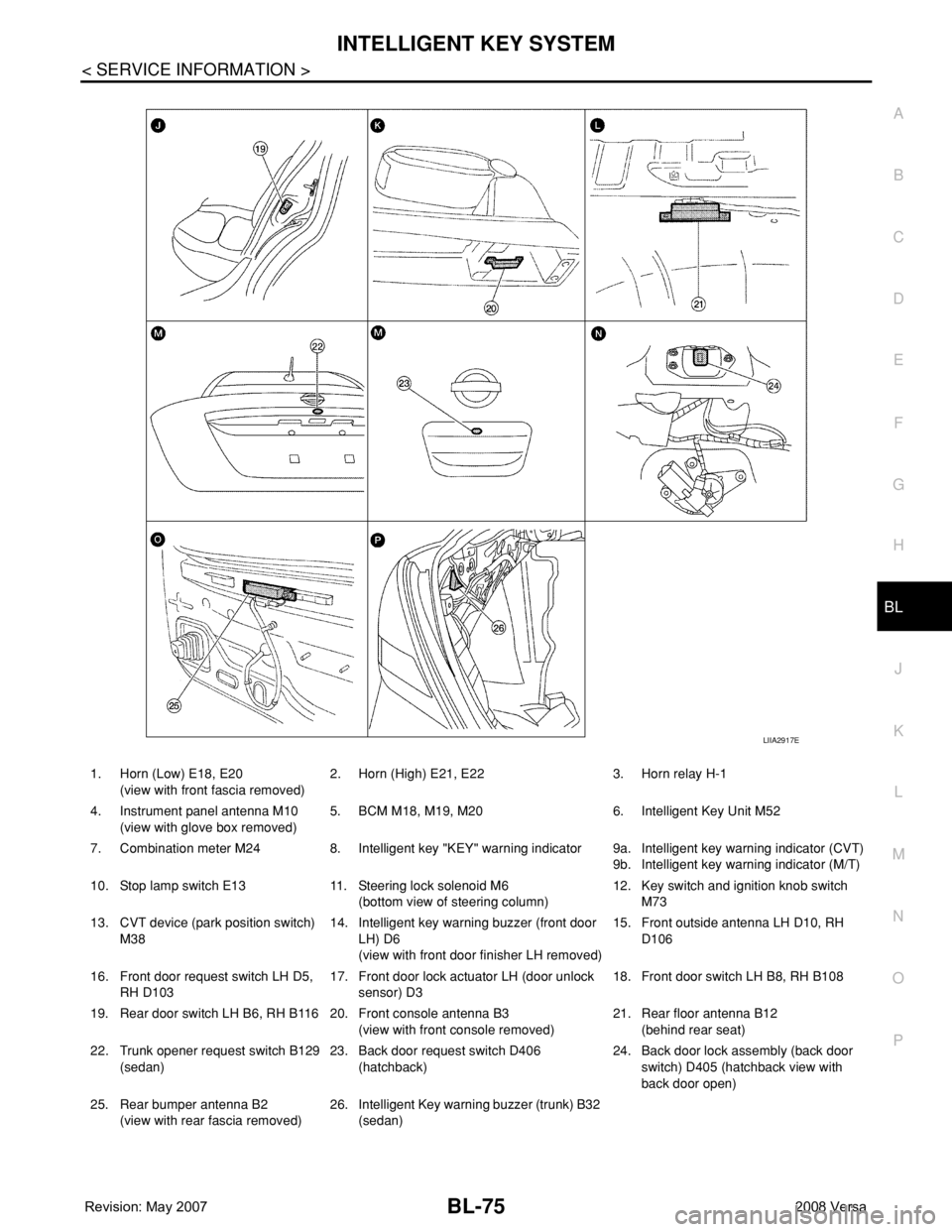
1. Horn (Low) E18, E20
(view with front fascia removed)2. Horn (High) E21, E22 3. Horn relay H-1
4. Instrument panel antenna M10
(view with glove box removed)5. BCM M18, M19, M20 6. Intelligent Key Unit M52
7. Combination meter M24 8. Intelligent key "KEY" warning indicator 9a.
9b.Intelligent key warning indicator (CVT)
Intelligent key warning indicator (M/T)
10. Stop lamp switch E13 11. Steering lock solenoid M6
(bottom view of steering column)12. Key switch and ignition knob switch
M73
13. CVT device (park position switch)
M3814. Intelligent key warning buzzer (front door
LH) D6
(view with front door finisher LH removed)15. Front outside antenna LH D10, RH
D106
16. Front door request switch LH D5,
RH D10317. Front door lock actuator LH (door unlock
sensor) D318. Front door switch LH B8, RH B108
19. Rear door switch LH B6, RH B116 20. Front console antenna B3
(view with front console removed)21. Rear floor antenna B12
(behind rear seat)
22. Trunk opener request switch B129
(sedan)23. Back door request switch D406
(hatchback)24. Back door lock assembly (back door
switch) D405 (hatchback view with
back door open)
25. Rear bumper antenna B2
(view with rear fascia removed)26. Intelligent Key warning buzzer (trunk) B32
(sedan)
LIIA2917E