Page 211 of 2771

TROUBLE DIAGNOSIS FOR SYMPTOMS
AT-199
< SERVICE INFORMATION >
D
E
F
G
H
I
J
K
L
MA
B
AT
N
O
P
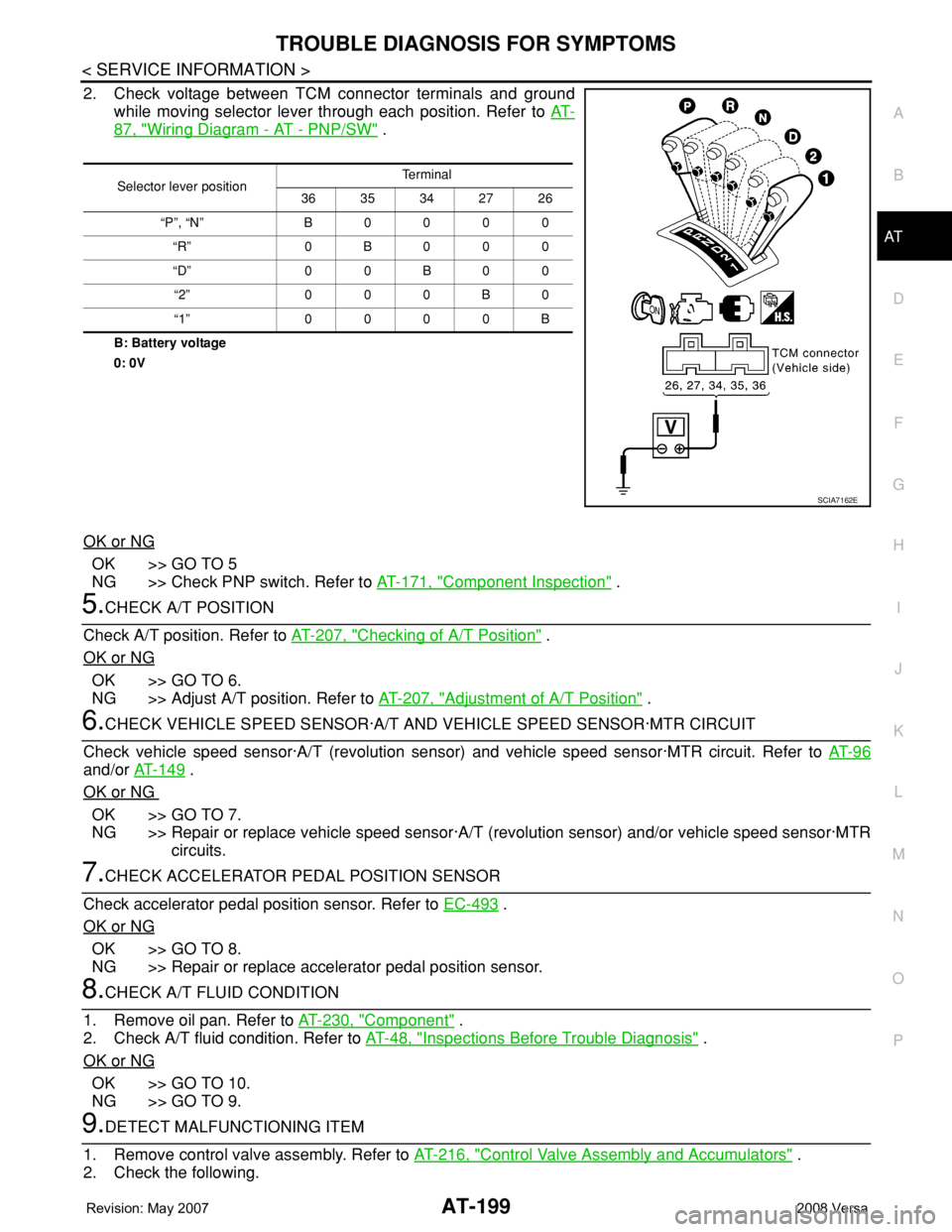
2. Check voltage between TCM connector terminals and ground
while moving selector lever through each position. Refer to AT-
87, "Wiring Diagram - AT - PNP/SW" .
B: Battery voltage
0: 0V
OK or NG
OK >> GO TO 5
NG >> Check PNP switch. Refer to AT-171, "
Component Inspection" .
5.CHECK A/T POSITION
Check A/T position. Refer to AT-207, "
Checking of A/T Position" .
OK or NG
OK >> GO TO 6.
NG >> Adjust A/T position. Refer to AT-207, "
Adjustment of A/T Position" .
6.CHECK VEHICLE SPEED SENSOR·A/T AND VEHICLE SPEED SENSOR·MTR CIRCUIT
Check vehicle speed sensor·A/T (revolution sensor) and vehicle speed sensor·MTR circuit. Refer to AT- 9 6
and/or AT-149 .
OK or NG
OK >> GO TO 7.
NG >> Repair or replace vehicle speed sensor·A/T (revolution sensor) and/or vehicle speed sensor·MTR
circuits.
7.CHECK ACCELERATOR PEDAL POSITION SENSOR
Check accelerator pedal position sensor. Refer to EC-493
.
OK or NG
OK >> GO TO 8.
NG >> Repair or replace accelerator pedal position sensor.
8.CHECK A/T FLUID CONDITION
1. Remove oil pan. Refer to AT-230, "
Component" .
2. Check A/T fluid condition. Refer to AT-48, "
Inspections Before Trouble Diagnosis" .
OK or NG
OK >> GO TO 10.
NG >> GO TO 9.
9.DETECT MALFUNCTIONING ITEM
1. Remove control valve assembly. Refer to AT-216, "
Control Valve Assembly and Accumulators" .
2. Check the following.
Selector lever positionTe r m i n a l
36 35 34 27 26
“P”, “N” B 0 0 0 0
“R” 0B000
“D” 0 0 B 0 0
“2” 0 0 0 B 0
“1” 0 0 0 0 B
SCIA7162E
Page 213 of 2771
TROUBLE DIAGNOSIS FOR SYMPTOMS
AT-201
< SERVICE INFORMATION >
D
E
F
G
H
I
J
K
L
MA
B
AT
N
O
P
• Closed throttle position signal and wide open throttle position sig-
nal
ECM judges throttle opening based on a signal from accelerator
pedal position sensor, and sends the signal via CAN communica-
tion to the TCM.
DIAGNOSTIC PROCEDURE
NOTE:
The diagnostic procedure includes inspection for the PNP stitch, overdrive control switch, closed throttle posi-
tion signal and wide open throttle position signal circuit. Refer to AT-167
.
SCIA7143E
Page 233 of 2771

ON-VEHICLE SERVICE
AT-221
< SERVICE INFORMATION >
D
E
F
G
H
I
J
K
L
MA
B
AT
N
O
P
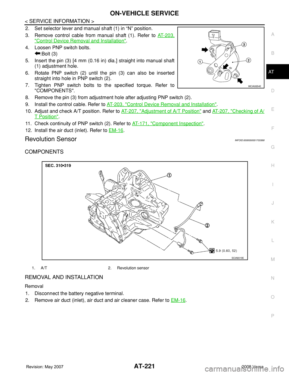
2. Set selector lever and manual shaft (1) in “N” position.
3. Remove control cable from manual shaft (1). Refer to AT-203,
"Control Device Removal and Installation".
4. Loosen PNP switch bolts.
:Bolt (3)
5. Insert the pin (3) [4 mm (0.16 in) dia.] straight into manual shaft
(1) adjustment hole.
6. Rotate PNP switch (2) until the pin (3) can also be inserted
straight into hole in PNP switch (2).
7. Tighten PNP switch bolts to the specified torque. Refer to
"COMPONENTS".
8. Remove the pin (3) from adjustment hole after adjusting PNP switch (2).
9. Install the control cable. Refer to AT-203, "
Control Device Removal and Installation".
10. Adjust and check A/T position. Refer to AT-207, "
Adjustment of A/T Position" and AT-207, "Checking of A/
T Position".
11. Check continuity of PNP switch (2). Refer to AT-171, "
Component Inspection".
12. Install the air duct (inlet). Refer to EM-16
.
Revolution SensorINFOID:0000000001703368
COMPONENTS
REMOVAL AND INSTALLATION
Removal
1. Disconnect the battery negative terminal.
2. Remove air duct (inlet), air duct and air cleaner case. Refer to EM-16
.
WCIA0654E
1. A/T 2. Revolution sensor
SCIA8019E
Page 234 of 2771
AT-222
< SERVICE INFORMATION >
ON-VEHICLE SERVICE
3. Disconnect revolution sensor harness connector.
4. Remove clip (A).
5. Remove revolution sensor (1) from A/T.
: Bolt (2)
6. Remove O-ring from revolution sensor (1)
Installation
Installation is in the reverse order of removal.
CAUTION:
• Do not reuse O-ring.
• Apply ATF to O-ring.
• Ensure revolution sensor harness is firmly secured with bolt.
(1): Revolution sensor
: Bolt (1)
Turbine Revolution Sensor (Power Train Revolution Sensor)INFOID:0000000001703369
COMPONENTS
REMOVAL AND INSTALLATION
Removal
1. Disconnect the battery negative terminal.
2. Remove air duct (inlet). Refer to EM-16
.
WCIA0655E
WCIA0656E
1. A/T 2. O-ring 3. Turbine revolution sensor (power
train revolution sensor)
SCIA8020E
Page 235 of 2771
ON-VEHICLE SERVICE
AT-223
< SERVICE INFORMATION >
D
E
F
G
H
I
J
K
L
MA
B
AT
N
O
P
3. Disconnect turbine revolution sensor (power train revolution
sensor) harness connector (1).
4. Remove turbine revolution sensor (power train revolution sen-
sor) bolt.
: Bolt (1)
5. Remove turbine revolution sensor (power train revolution sen-
sor) (2) from A/T.
6. Remove O-ring from turbine revolution sensor (power train revo-
lution sensor) (2).
Installation
Installation is in the reverse order of removal.
CAUTION:
• Do not reuse O-ring.
• Apply ATF to O-ring.
Differential Side Oil SealINFOID:0000000001703370
COMPONENTS
REMOVAL AND INSTALLATION
Removal
1. Remove front drive shaft. Refer to FA X - 8.
2. Remove differential side oil seals using a flat-bladed screw-
driver.
CAUTION:
Be careful not to scratch transaxle case and converter
housing.
Installation
WCIA0658E
1. A/T 2. LH differential side oil seal 3. RH differential side oil seal
SCIA8021E
SCIA4857E
Page 239 of 2771

TRANSAXLE ASSEMBLY
AT-227
< SERVICE INFORMATION >
D
E
F
G
H
I
J
K
L
MA
B
AT
N
O
P
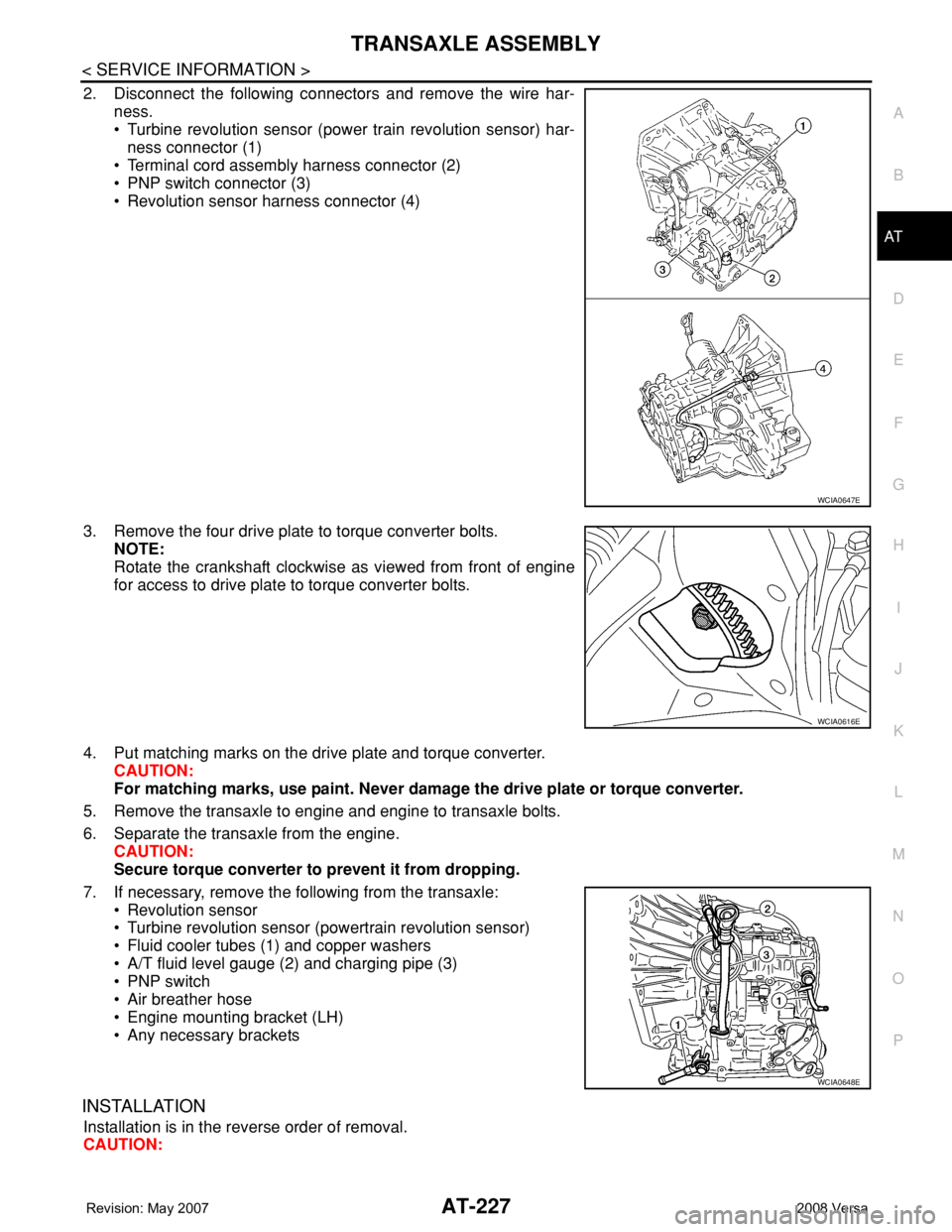
2. Disconnect the following connectors and remove the wire har-
ness.
• Turbine revolution sensor (power train revolution sensor) har-
ness connector (1)
• Terminal cord assembly harness connector (2)
• PNP switch connector (3)
• Revolution sensor harness connector (4)
3. Remove the four drive plate to torque converter bolts.
NOTE:
Rotate the crankshaft clockwise as viewed from front of engine
for access to drive plate to torque converter bolts.
4. Put matching marks on the drive plate and torque converter.
CAUTION:
For matching marks, use paint. Never damage the drive plate or torque converter.
5. Remove the transaxle to engine and engine to transaxle bolts.
6. Separate the transaxle from the engine.
CAUTION:
Secure torque converter to prevent it from dropping.
7. If necessary, remove the following from the transaxle:
• Revolution sensor
• Turbine revolution sensor (powertrain revolution sensor)
• Fluid cooler tubes (1) and copper washers
• A/T fluid level gauge (2) and charging pipe (3)
• PNP switch
• Air breather hose
• Engine mounting bracket (LH)
• Any necessary brackets
INSTALLATION
Installation is in the reverse order of removal.
CAUTION:
WCIA0647E
WCIA0616E
WCIA0648E
Page 248 of 2771

AT-236
< SERVICE INFORMATION >
OVERHAUL
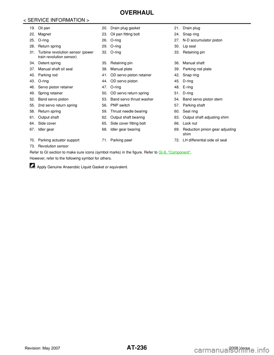
19. Oil pan 20. Drain plug gasket 21. Drain plug
22. Magnet 23. Oil pan fitting bolt 24. Snap ring
25. O-ring 26. O-ring 27. N-D accumulator piston
28. Return spring 29. O-ring 30. Lip seal
31. Turbine revolution sensor (power
train revolution sensor)32. O-ring 33. Retaining pin
34. Detent spring 35. Retaining pin 36. Manual shaft
37. Manual shaft oil seal 38. Manual plate 39. Parking rod plate
40. Parking rod 41. OD servo piston retainer 42. Snap ring
43. O-ring 44. OD servo piston 45. D-ring
46. Servo piston retainer 47. O-ring 48. E-ring
49. Spring retainer 50. OD servo return spring 51. D-ring
52. Band servo piston 53. Band servo thrust washer 54. Band servo piston stem
55. 2nd servo return spring 56. PNP switch 57. Parking shaft
58. Return spring 59. Thrust needle bearing 60. Seal ring
61. Output shaft 62. Output shaft bearing 63. Output shaft adjusting shim
64. Side cover 65. Side cover fitting bolt 66. Lock nut
67. Idler gear 68. Idler gear bearing 69. Reduction pinion gear adjusting
shim
70. Parking actuator support 71. Parking pawl 72. LH differential side oil seal
73. Revolution sensor
Refer to GI section to make sure icons (symbol marks) in the figure. Refer to GI-8, "
Component".
However, refer to the following symbol for others.
: Apply Genuine Anaerobic Liquid Gasket or equivalent.
Page 253 of 2771
DISASSEMBLY
AT-241
< SERVICE INFORMATION >
D
E
F
G
H
I
J
K
L
MA
B
AT
N
O
P
5. Remove turbine revolution sensor (power train revolution sen-
sor) (1) from transaxle case (2).
: Bolt (1)
6. Remove O-ring (3) from turbine revolution sensor (power train
revolution sensor) (1).
7. Remove revolution sensor (1) from transaxle case (2).
: Bolt (2)
8. Remove plug or speedometer pinion according to the following procedures.
a. With ABS
i. Remove plug (1) from converter housing (2).
: Bolt (1)
ii. Remove O-ring (3) from plug (1).
b. Without ABS
i. Remove speedometer pinion (1) from converter housing (2).
: Bolt (1)
ii. Remove O-ring (3) from speedometer pinion (1).
SCIA7004J
SCIA7170J
SCIA7747E
SCIA7462E