2008 MERCEDES-BENZ GLK SUV tow
[x] Cancel search: towPage 240 of 261
When towing, observe the legal requirements
in all countries concerned.
!
When towing, pull away slowly and with-
out jerking. If the tractive power is too high,
the vehicles could be damaged.
! Do not use the towing eye for recovery,
as this could damage the vehicle. If in
doubt, recover the vehicle with a crane.
! You may tow the vehicle for a maximum
of 50 km. A towing speed of 50 km/hm ust
not be exceeded.
For towing distances over 50 km, the entire
vehicle needs to be lifted up and transpor-
ted.
! Only secure the tow cable or towing bar
to the towing eyes. You may otherwise
damage the vehicle.
R Tow-starting the vehicle is not permitted.
R The vehicle is equipped with 4MATIC and
must not be towed with the front or rear
axle raised.
R If the engine does not start, try jump-start-
ing it (Y page 234).
R If it is not possible to jump-start the vehicle,
have it towed to the nearest qualified spe-
cialist workshop, e.g. a Mercedes-Benz
Service Centre.
R If the vehicle has suffered transmission
damage, have it carried away on a trans-
porter or trailer.
R The automatic transmission selector lever
must be in the Nposition when towing the
vehicle away.
R If you are towing the vehicle, move the
automatic transmission selector lever to
N and turn the key to position
2 (Y page 61) in the ignition lock.
R Before towing the vehicle, make sure that
the battery is connected and charged. Oth-
erwise: -
you cannot switch on the ignition.
- you cannot move the selector lever to
N.
- you have no support when braking.
i Switch off the automatic locking feature
before the vehicle is towed. Otherwise, you
could be locked out when pushing or tow-
ing the vehicle.
Deactivate tow-away protection* before
the vehicle is towed ( Ypage 55). Fitting the towing eye
Vehicles with a trailer tow hitch: if you
intend to use the vehicle for towing, fit the ball
coupling (Y page 162)and connect the towbar
to it.
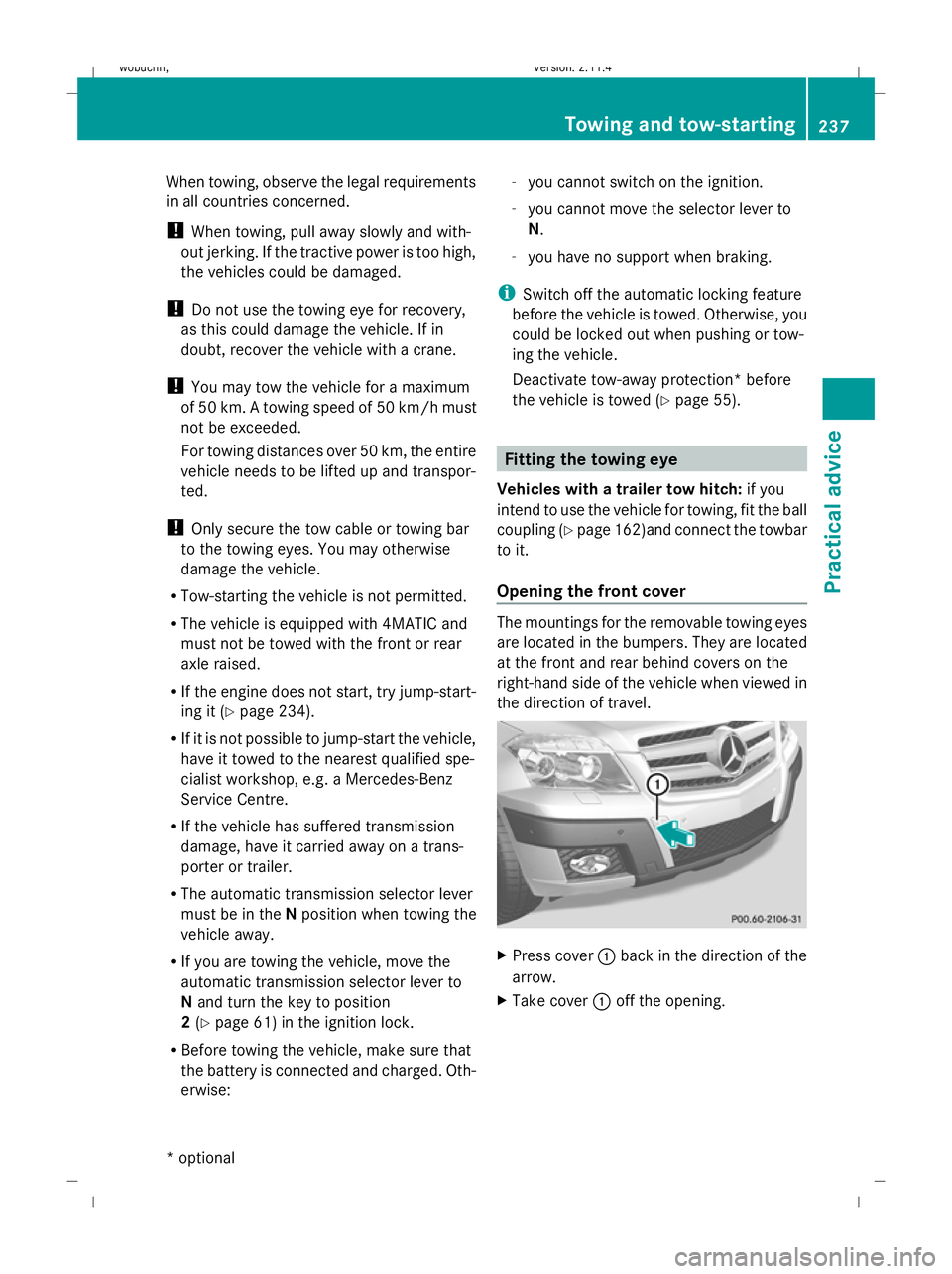
Opening the front cover The mountings for the removable towing eyes
are located in the bumpers. They are located
at the front and rear behind covers on the
right-hand side of the vehicle when viewed in
the direction of travel. X
Press cover :back in the direction of the
arrow.
X Take cover :off the opening. Towing and tow-starting
237Practical advice
* optional
X204_AKB; 1; 5, en-GB
wobuchh,
Version: 2.11.4 2008-10-15T13:20:56+02:00 - Seite 237 ZDateiname: 6515_0671_02_buchblock.pdf; preflight
Page 241 of 261
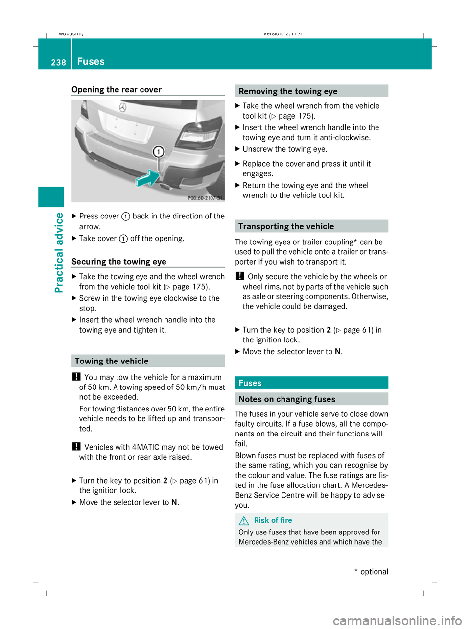
Opening the rear cover
X
Press cover :back in the direction of the
arrow.
X Take cover :off the opening.
Securing the towing eye X
Take the towing eye and the wheel wrench
from the vehicle tool kit (Y page 175).
X Screw in the towing eye clockwise to the
stop.
X Insert the wheel wrench handle into the
towing eye and tighten it. Towing the vehicle
! You may tow the vehicle for a maximum
of 50 km. A towing speed of 50 km/hm ust
not be exceeded.
For towing distances over 50 km, the entire
vehicle needs to be lifted up and transpor-
ted.
! Vehicles with 4MATIC may not be towed
with the front or rear axle raised.
X Turn the key to position 2(Y page 61) in
the ignition lock.
X Move the selector lever to N. Removing the towing eye
X Take the wheel wrench from the vehicle
tool kit (Y page 175).
X Insert the wheel wrench handle into the
towing eye and turn it anti-clockwise.
X Unscrew the towing eye.
X Replace the cover and press it until it
engages.
X Return the towing eye and the wheel
wrench to the vehicle tool kit. Transporting the vehicle
The towing eyes or trailer coupling* can be
used to pull the vehicle onto a trailer or trans-
porter if you wish to transport it.
! Only secure the vehicle by the wheels or
wheel rims, not by parts of the vehicle such
as axle or steering components. Otherwise,
the vehicle could be damaged.
X Turn the key to position 2(Y page 61) in
the ignition lock.
X Move the selector lever to N. Fuses
Notes on changing fuses
The fuses in your vehicle serve to close down
faulty circuits. If a fuse blows, all the compo-
nents on the circuit and their functions will
fail.
Blown fuses must be replaced with fuses of
the same rating, which you can recognise by
the colour and value. The fuse ratings are lis-
ted in the fuse allocation chart. A Mercedes-
Benz Service Centre will be happy to advise
you. G
Risk of fire
Only use fuses that have been approved for
Mercedes-Benz vehicles and which have the 238 FusesPractical advice
* optional
X204_AKB; 1; 5, en-GB
wobuchh,
Version: 2.11.4 2008-10-15T13:20:56+02:00 - Seite 238Dateiname: 6515_0671_02_buchblock.pdf; preflight
Page 242 of 261
correct fuse rating for the systems con-
cerned. Do not attempt to repair or bridge
faulty fuses. Otherwise, a circuit overload
could cause a fire. Have the cause traced and
rectified at a qualified specialist workshop,
e.g. a Mercedes-Benz Service Centre.
If the newly inserted fuse also blows, have the
cause traced and rectified at a qualified spe-
cialist workshop, e.g. a Mercedes-Benz
Service Centre.
! Only use fuses that have been approved
for Mercedes-Benz vehicles and which
have the correct fuse rating for the system
concerned. Otherwise, components or sys-
tems could be damaged.
The fuses are located in various fuse boxes:
R fuse box on the driver's side of the dash-
board*
R fuse box in the engine compartment on the
driver's side
R fuse box in the stowage well under the lug-
gage compartment floor on the right-hand
side of the vehicle
Fuse allocation chart The fuse allocation chart is located with the
vehicle tool kit (Y
page 175) in the stowage
compartment under the luggage compart-
ment floor. Before changing a fuse
X Park the vehicle.
X Switch off all electrical consumers.
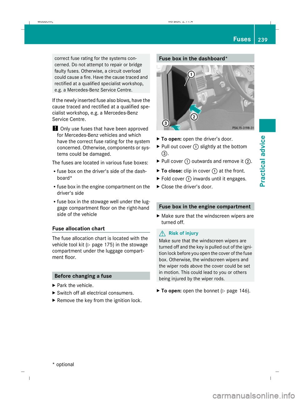
X Remove the key from the ignition lock. Fuse box in the dashboard*
X
To open: open the driver’s door.
X Pull out cover :slightly at the bottom
=.
X Pull cover :outwards and remove it ;.
X To close: clip in cover :at the front.
X Fold cover :inwards until it engages.
X Close the driver's door. Fuse box in the engine compartment
X Make sure that the windscreen wipers are
turned off. G
Risk of injury
Make sure that the windscreen wipers are
turned off and the key is pulled out of the igni-
tion lock before you open the cover of the fuse
box. Otherwise, the windscreen wipers and
the wiper rods above the cover could be set
in motion. This could lead to you or others
being injured by the wiper rods.
X To open: open the bonnet (Y page 146). Fuses
239Practical advice
* optional
X204_AKB; 1; 5, en-GB
wobuchh,
Version: 2.11.4 2008-10-15T13:20:56+02:00 - Seite 239 ZDateiname: 6515_0671_02_buchblock.pdf; preflight
Page 243 of 261
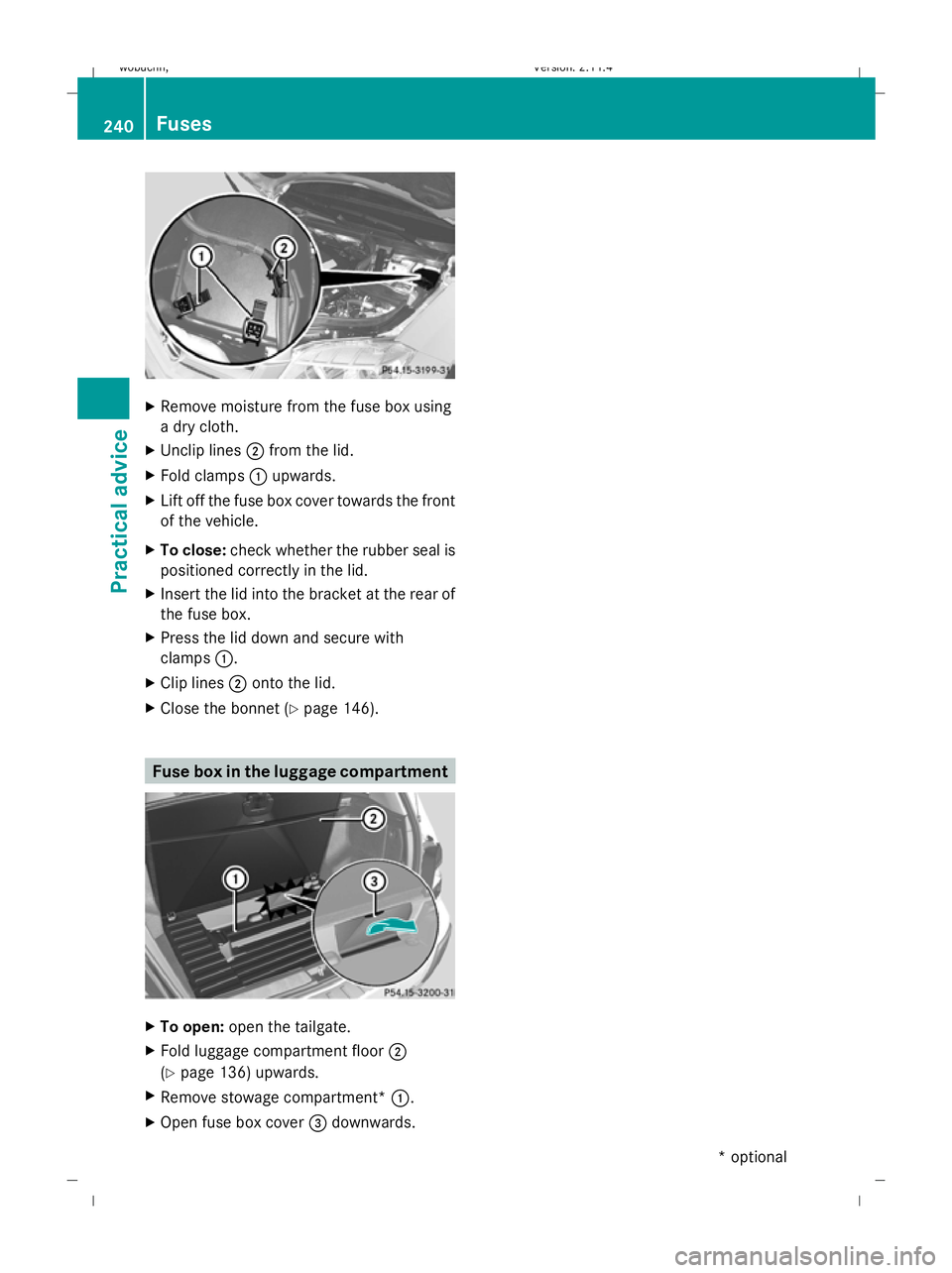
X
Remove moisture from the fuse box using
a dry cloth.
X Unclip lines ;from the lid.
X Fold clamps :upwards.
X Lift off the fuse box cover towards the front
of the vehicle.
X To close: check whether the rubber seal is
positioned correctly in the lid.
X Insert the lid into the bracket at the rear of
the fuse box.
X Press the lid down and secure with
clamps :.
X Clip lines ;onto the lid.
X Close the bonnet (Y page 146). Fuse box in the luggage compartment
X
To open: open the tailgate.
X Fold luggage compartment floor ;
(Y page 136) upwards.
X Remove stowage compartment* :.
X Open fuse box cover =downwards. 240 FusesPractical advice
* optional
X204_AKB; 1; 5, en-GB
wobuchh,
Version: 2.11.4 2008-10-15T13:20:56+02:00 - Seite 240Dateiname: 6515_0671_02_buchblock.pdf; preflight
Page 247 of 261
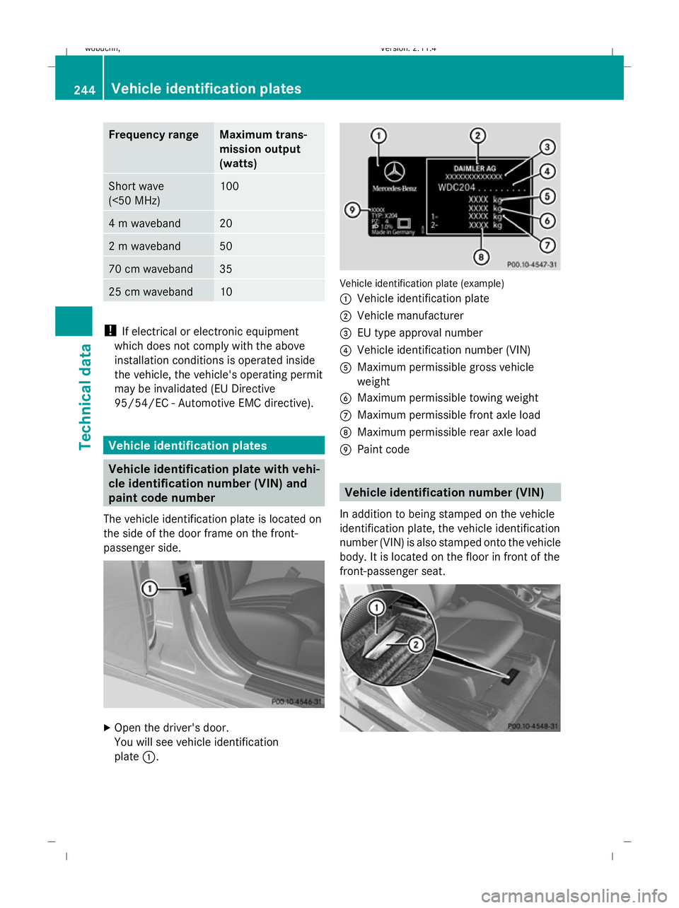
Frequency range Maximum trans-
mission output
(watts)
Short wave
(<50 MHz) 100
4 m waveband 20
2 m waveband 50
70 cm waveband 35
25 cm waveband 10
!
If electrical or electronic equipment
which does not comply with the above
installation conditions is operated inside
the vehicle, the vehicle's operating permit
may be invalidated (EU Directive
95/54/EC - Automotive EMC directive). Vehicle identification plates
Vehicle identification plate with vehi-
cle identification number (VIN) and
paint code number
The vehicle identification plate is located on
the side of the door frame on the front-
passenger side. X
Open the driver's door.
You will see vehicle identification
plate :. Vehicle identification plate (example)
: Vehicle identification plate
; Vehicle manufacturer
= EU type approval number
? Vehicle identification number (VIN)
A Maximum permissible gross vehicle
weight
B Maximum permissible towing weight
C Maximum permissible front axle load
D Maximum permissible rear axle load
E Paint code Vehicle identification number (VIN)
In addition to being stamped on the vehicle
identification plate, the vehicle identification
number (VIN) is also stamped onto the vehicle
body. It is located on the floor in front of the
front-passenger seat. 244 Vehicle identification platesTechnical data
X204_AKB; 1; 5, en-GB
wobuchh,
Version: 2.11.4 2008-10-15T13:20:56+02:00 - Seite 244Dateiname: 6515_0671_02_buchblock.pdf; preflight
Page 249 of 261
injection system. Damage resulting from
adding the wrong fuel is not covered by the
warranty.
Further information on refuelling and on fuels
(Y page 144).
Notes on fuel consumption The vehicle will use more fuel than usual in
the following situations:
R at very low temperatures
R in urban traffic
R on short trips
R when towing a trailer
R in mountainous terrain
The consumption figures have been deter-
mined in accordance with EU Directive
RL 80 /1268 /EEC.
i Only for certain countries: the respective
current consumption and emission values
of your vehicle can be found in the COC
papers (EC CERTIFICATE OF CONFORM-
ITY). These documents are supplied when
the vehicle is delivered.
! Do not use any special additives, as they
can cause malfunctions and engine dam-
age. Damage resulting from the use of such
additives is not covered by the Mercedes-
Benz warranty. H
Environmental note
CO 2(carbon dioxide) is the gas which scien-
tists believe to be principally responsible for global warming (the greenhouse effect). Your
vehicle's CO
2emissions are directly related
to fuel consumption and therefore depend on:
R efficient use of the fuel by the engine
R driving style
R other non-technical factors, such as envi-
ronmental influences or road conditions
You can minimise your vehicle's CO 2emis-
sions by driving carefully and having it serv-
iced regularly. Engine oil
Only Mercedes-Benz approved engine oils
may be used in Mercedes-Benz engines.
A list of the engine oils tested and approved
in accordance with the Mercedes-Benz Spec-
ifications for Service Products can be called
up by visiting http:\\bevo.daimler.co m and
en tering the MB Sheet number. Further infor-
mation on tested and approved engine oils
can be obtained from any Mercedes-Benz
Service Centre. Engine oils which have been
approved by Mercedes-Benz have the MB
Sheet number indicated on the oil container
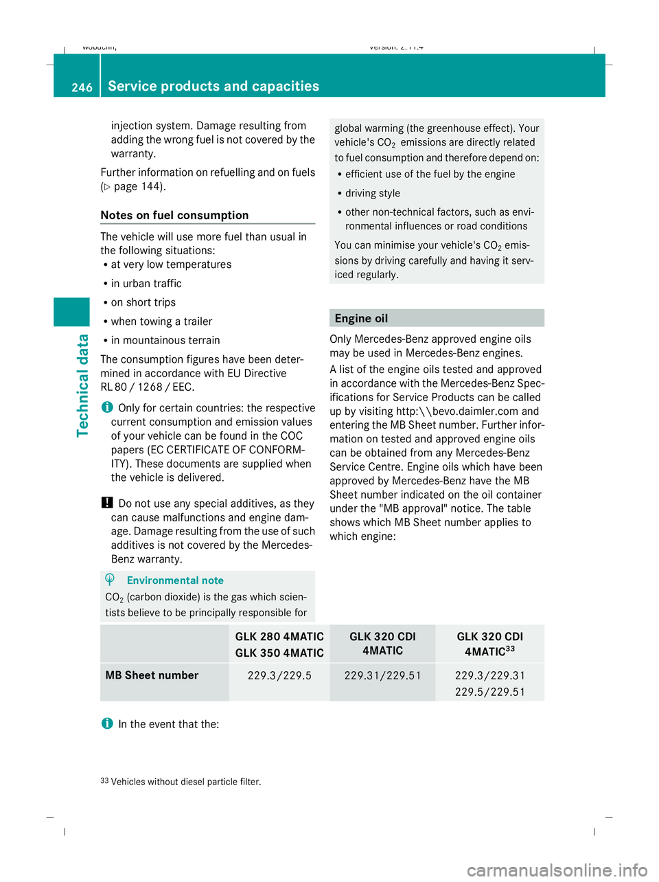
under the "MB approval" notice. The table
shows which MB Sheet number applies to
which engine: GLK 280 4MATIC
GLK 350 4MATIC GLK 320 CDI
4MATIC GLK 320 CDI
4MATIC 33 MB Sheet number
229.3/229.5 229.31/229.51 229.3/229.31
229.5/229.51
i
In the event that the:
33 Vehicles without diesel particle filter. 246 Service products and capacitiesTechnical data
X204_AKB; 1; 5, en-GB
wobuchh
,V ersion: 2.11.4
2008-10-15T13:20:56+02:00 - Seite 246 Dateiname: 6515_0671_02_buchblock.pdf; preflight
Page 256 of 261
GLK 280 / GLK 350 / GLK 320 CDI
RA
Summer tyres
40 255/40 R20 101 W XL
Light-alloy wheels
9.5J x 20 H2 ET 57
Emergency spare wheel*
Depending on the country, the engine and the wheels fitted, your vehicle may be equipped
with TIREFIT or a collapsible emergency spare wheel*. Collapsible emergency spare wheel*
41 GLK 280 / GLK 350 / GLK 320 CDI
17" Tyres
185/75 - 17 98P
Tyre pressure
2.8 bar
Wheels
6.0B x 17 H2 ET 25
Trailer coupling*
Mounting dimensions
G
Risk of accident
Only have a trailer coupling retrofitted at a
qualified specialist workshop which has the
necessary specialist knowledge and tools to
carry out the work required. Mercedes-Benz
recommends that you use a Mercedes-Benz
Service Centre for this purpose. In particular,
work relevant to safety or on safety-related
systems must be carried out at a qualified
specialist workshop.
! If you have a trailer tow hitch retrofitted,
changes to the cooling system may be nec-
essary, depending on the vehicle type.
If you have a trailer tow hitch retrofitted,
observe the anchorage points on the chas-
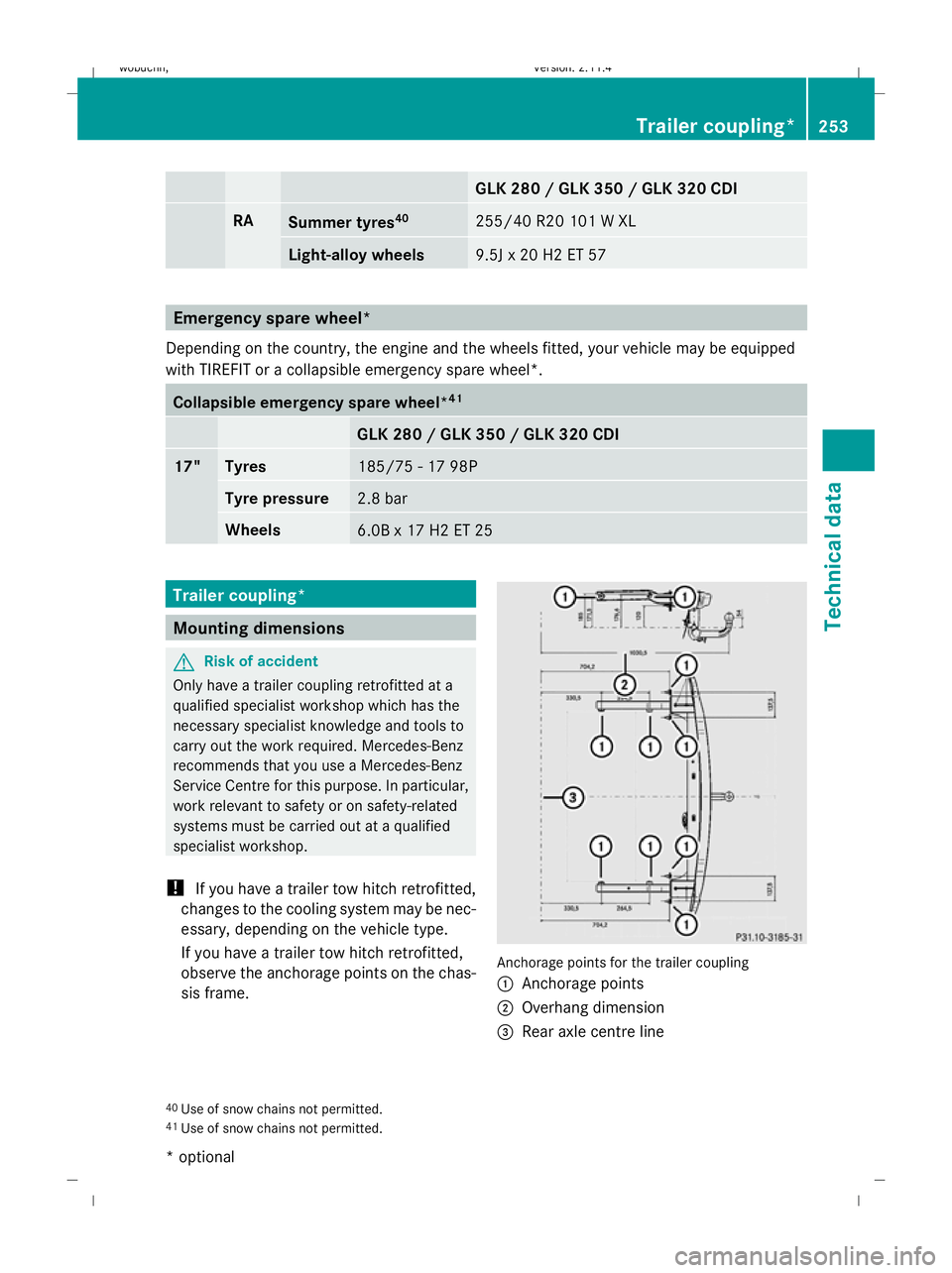
sis frame. Anchorage points for the trailer coupling
:
Anchorage points
; Overhang dimension
= Rear axle centre line
40 Use of snow chains not permitted.
41 Use of snow chains not permitted. Trailer coupling*
253Technical data
* optional
X204_AKB; 1; 5, en-GB
wobuchh,
Version: 2.11.4
2008-10-15T13:20:56+02:00 - Seite 253 ZDateiname: 6515_0671_02_buchblock.pdf; preflight
Page 257 of 261
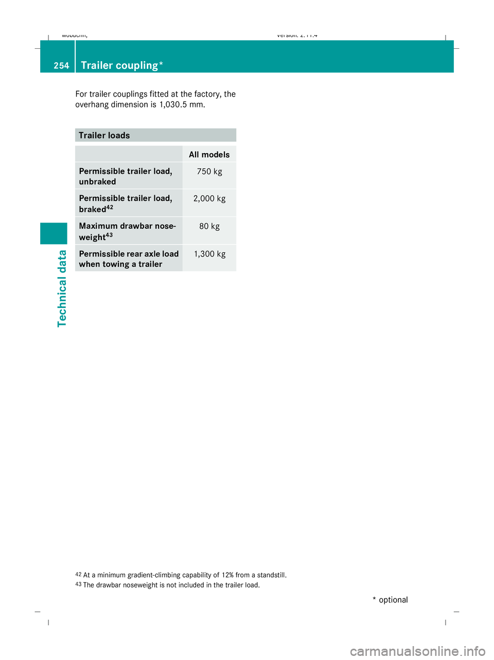
For trailer couplings fitted at the factory, the
overhang dimension is 1,030.5 mm. Trailer loads
All models
Permissible trailer load,
unbraked
750 kg
Permissible trailer load,
braked
42 2,000 kg
Maximum drawbar nose-
weight
43 80 kg
Permissible rear axle load
when towing a trailer
1,300 kg
42
At a minimum gradient-climbing capability of 12% from a standstill.
43 The drawbar noseweight is not included in the trailer load. 254
Trailer coupling*Technical data
* optional
X204_AKB; 1; 5, en-GB
wobuchh
,V ersion: 2.11.4
2008-10-15T13:20:56+02:00 - Seite 254 Dateiname: 6515_0671_02_buchblock.pdf; preflight