2008 MERCEDES-BENZ GLK SUV tow bar
[x] Cancel search: tow barPage 13 of 261
Dipped-beam headlamps.
.................75
Display messages (luxury multi-
function steering wheel) .................194
Display messages (multi-function
steering wheel). .............................. 194
Foglamps. ................................... 75, 78
Hazard warning lamps. .....................76
Headlamp flasher.............................. 76
Headlamp range. .............................. 77
Light switch. ..................................... 74
Main-beam headlamps..................... .76
Motorway mode ................................ 78
Rear foglamp. ................................... 75
Switching the daytime driving
lights on/off (on-board computer,
luxury multi-function steering
wheel). ............................................ 102
Switching the exterior lighting
delayed switch-off on/off (on-
board computer, luxury multi-
function steering wheel) .................103
Switching the Intelligent Light
System on or off (on-board com-
puter, luxury multi-function steer-
ing wheel). ...................................... 103
Switching the surround lighting
on/off (on-board computer,
luxury multi-function steering
wheel). ............................................ 103
Turn signals. ..................................... 76
LIM indicator lamp
Cruise control. ................................ 108
Variable Speedtronic. .....................111
Loading guidelines .............................129
Locking Automatic. ........................................ 59
Emergency locking .........................214
From the inside (central locking
button) .............................................. 59
Luggage compartment enlarge-
ment.................................................... 132
Luggage compartment floor opening/closing. ............................ 136
stowage well, unde r........................ 136
Luggage cover .................................... 133
Luggage net Front-passenger footwell ................131Lumbar support
.................................... 65
4-way. ............................................... 65
Luxury multi-function steering
wheel..................................................... 93
Overview. .......................................... 29 M
Main-beam headlamps Display message ............................. 192
Maintenance
Battery ............................................ 232
Manual drive program .........................88
Maximum speed................................. 249
Memory card (on-board computer,
luxury multi-function steering
wheel).................................................... 99
Memory function.................................. 69
Menu (luxury multi-function steer-
ing wheel)
Audio. ............................................... 98
Menu overview................................. .95
Navigation......................................... 97
Service............................................ 101
Telephone. ........................................ 99
Trip computer. .................................. 95
Menu (multi-function steering wheel)
Menu overview................................. .92
Range/current fuel consumption...... 93
Setting the time/dat e.......................93
Standard display. .............................. 92
Trip computer. .................................. 92
Messages
see Display messages
see Warning and indicator lamps
Minispare emergency spare wheel
Technical data. ............................... 253
Mirrors
Sun visor......................................... 138
see Exterior mirrors or Rear-view mirror
Mobile phone...................................... 140
Installation. ..................................... 243
On-board computer (luxury multi-
function steering wheel) ...................99
Modifying the programming
Key. .................................................. 5810 Index
X204_AKB; 1; 5, en-GB
wobuchh,
Version: 2.11.4 2008-10-15T13:20:56+02:00 - Seite 10Dateiname: 6515_0671_02_buchblock.pdf; preflight
Page 117 of 261
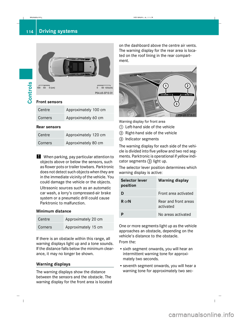
Front sensors
Centre Approximately 100 cm
Corners Approximately 60 cm
Rear sensors
Centre Approximately 120 cm
Corners Approximately 80 cm
!
When parking, pay particular attention to
objects above or below the sensors, such
as flower pots or trailer towbars. Parktronic
does not detect such objects when they are
in the immediate vicinity of the vehicle. You
could damage the vehicle or the objects.
Ultrasonic sources such as an automatic
car wash, a lorry's compressed-air brake
system or a pneumatic drill could cause
Parktronic to malfunction.
Minimum distance Centre Approximately 20 cm
Corners Approximately 15 cm
If there is an obstacle within this range, all
warning displays light up and a tone sounds.
If the distance falls below the minimum clear-
ance, it may no longer be shown.
Warning displays The warning displays show the distance
between the sensors and the obstacle. The
warning display for the front area is located on the dashboard above the centre air vents.
The warning display for the rear area is loca-
ted on the roof lining in the rear compart-
ment.
Warning display for front area
:
Left-hand side of the vehicle
; Right-hand side of the vehicle
= Indicator segments
The warning display for each side of the vehi-
cle is divided into five yellow and two red seg-
ments. Parktronic is operational if yellow indi-
cator segments =light up.
The selector lever position determines which
warning display is active: Selector lever
position Warning display
D
Front area activated
R
orN Rear and front areas
activated
P
No areas activated
One or more segments light up as the vehicle
approaches an obstacle, depending on the
vehicle's distance to the obstacle.
From the:
R
sixth segment onwards, you will hear an
intermittent warning tone for approxi-
mately two seconds.
R seventh segment onwards, you will hear a
warning tone for approximately two sec- 114 Driving systemsControls
X204_AKB; 1; 5, en-GB
wobuchh,
Version: 2.11.4 2008-10-15T13:20:56+02:00 - Seite 114Dateiname: 6515_0671_02_buchblock.pdf; preflight
Page 167 of 261
removed, remove the ball coupling and clean
it.
If the ball coupling can still not be fitted
(locked) after it has been cleaned, remove the
ball coupling. The trailer coupling must then
not be used to tow a trailer, as safe operation
is not guaranteed.
Have the entire trailer coupling checked at a
qualified specialist workshop. Mercedes-
Benz recommends that you use a Mercedes-
Benz Service Centre for this purpose. In par-
ticular, work relevant to safety or on safety-
related systems must be carried out at a quali-
fied specialist workshop. Notes on towing a trailer
G
Risk of accident
When reversing the vehicle towards the
trailer, make sure there is nobody between
the trailer and the vehicle.
Couple and uncouple the trailer carefully. If
you do not couple the trailer to the towing
vehicle correctly, the trailer could become
detached.
Make sure that the following values are not
exceeded:
R the permissible trailer drawbar noseweight
R the permissible trailer load
R the permissible rear axle load of the towing
vehicle
R the maximum permissible gross vehicle
weight of both the towing vehicle and the
trailer
You will find the applicable permissible val-
ues, which must not be exceeded, in the vehi-
cle documents.
You will find the values approved by the man-
ufacturer on the vehicle identification plates
and those for the towing vehicle in the "Tech-
nical data" section. You will find installation dimensions and loads
in the "Technical data" section
(Y page 253).
The maximum drawbar load of the trailer
drawbar on the ball coupling is 80 kg. How-
ever, the actual noseweight must not exceed
the value given on the trailer coupling and
trailer identification plates. The lowest weight
applies.
! Use a noseweight as close as possible to
the maximum permissible noseweight. Do
not use a noseweight of less than 50 kg,
otherwise the trailer may come loose.
Bear in mind that the payload and the rear
axle load are reduced by the actual nose-
weight.
i The height of the ball coupling changes
with the load of the vehicle. If necessary,
use a trailer with a height-adjustable trailer
drawbar.
Coupling up a trailer G
Risk of injury
Do not disconnect a trailer with an engaged
overrun brake. Otherwise, your hand could
become trapped between the bumper and
trailer drawbar.
! Do not disconnect a trailer with an
engaged overrun brake. Otherwise, your
vehicle could be damaged by the rebound-
ing of the overrun brake.
X Position the trailer level behind the vehicle.
X Couple up the trailer.
X Establish the electrical connection
between the vehicle and the trailer.
Driving tips i
Observe the notes on ESP ®
trailer stabi-
lisation (Y page 53).
In Germany, the maximum permitted speed
for vehicle/trailer combinations is 80 km/h. 164
Trailer towing*Operation
* optional
X204_AKB; 1; 5, en-GB
wobuchh,
Version: 2.11.4 2008-10-15T13:20:56+02:00 - Seite 164Dateiname: 6515_0671_02_buchblock.pdf; preflight
Page 225 of 261
X
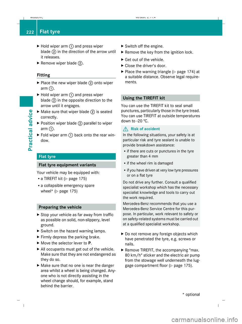
Hold wiper arm :and press wiper
blade ;in the direction of the arrow until
it releases.
X Remove wiper blade ;.
Fitting X
Place the new wiper blade ;onto wiper
arm :.
X Hold wiper arm :and press wiper
blade ;in the opposite direction to the
arrow until it engages.
X Make sure that wiper blade ;is seated
correctly.
X Position wiper blade ;parallel to wiper
arm :.
X Fold wiper arm :back onto the rear win-
dow. Flat tyre
Flat tyre equipment variants
Your vehicle may be equipped with:
R a TIREFIT kit (Y page 175)
R a collapsible emergency spare
wheel* (Y page 175) Preparing the vehicle
X Stop your vehicle as far away from traffic
as possible on solid, non-slippery, level
ground.
X Switch on the hazard warning lamps.
X Firmly depress the parking brake.
X Move the selector lever to P.
X All occupants must get out of the vehicle.
Make sure that they are not endangered as
they do so.
X Make sure that no one is near the danger
area whilst a wheel is being changed. Any-
one who is not directly assisting in the
wheel change should, for example, stand
behind the barrier. X
Switch off the engine.
X Remove the key from the ignition lock.
X Get out of the vehicle.
X Close the driver's door.
X Place the warning triangle (Y page 174) at
a suitable distance. Observe legal require-
ments. Using the TIREFIT kit
You can use the TIREFIT kit to seal small
punctures, particularly those in the tyre tread.
You can use TIREFIT at outside temperatures
down to -20 †. G
Risk of accident
In the following situations, your safety is at
particular risk and tyre sealant is unable to
provide breakdown assistance:
R if there are cuts or punctures in the tyre
greater than 4 mm
R if the wheel rim is damaged
R if you have driven at very low tyre pressures
or on a flat tyre
Do not drive any further. Consult a qualified
specialist workshop which has the necessary
specialist knowledge and tools to carry out
the work required.
Mercedes-Benz recommends that you use a
Mercedes-Benz Service Centre for this pur-
pose. In particular, work relevant to safety or
on safety-related systems must be carried out
at a qualified specialist workshop.
X Do not remove any foreign objects which
have penetrated the tyre, e.g. screws or
nails.
X Remove TIREFIT, the accompanying "max.
80 km/h" sticker and the electric air pump
from the stowage well underneath the lug-
gage compartment floor (Y page 175).222 Flat tyrePractical advice
* optional
X204_AKB; 1; 5, en-GB
wobuchh,
Version: 2.11.4 2008-10-15T13:20:56+02:00 - Seite 222Dateiname: 6515_0671_02_buchblock.pdf; preflight
Page 227 of 261
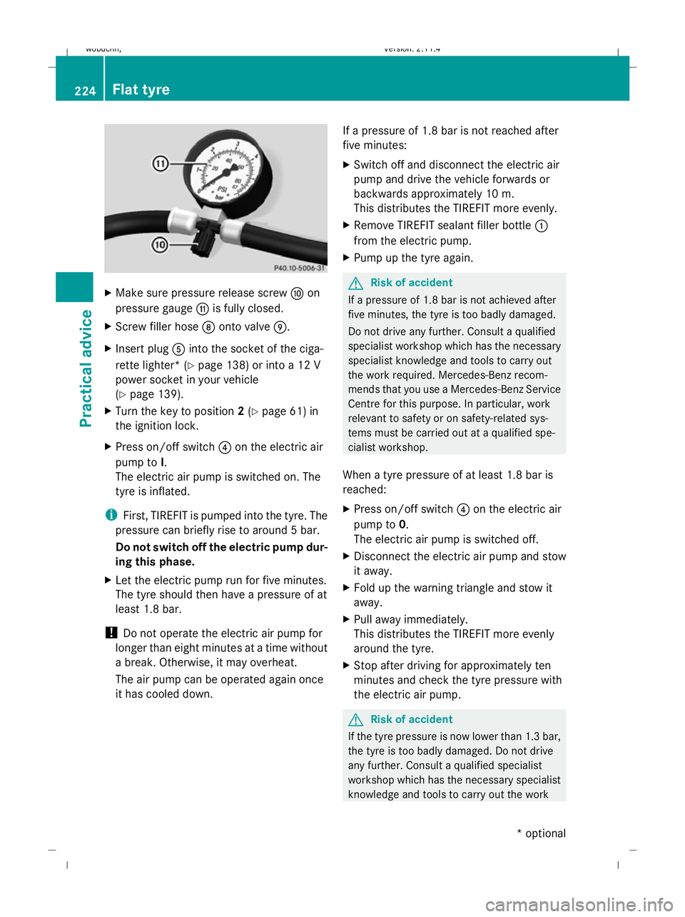
X
Make sure pressure release screw Fon
pressure gauge Gis fully closed.
X Screw filler hose Donto valve E.
X Insert plug Ainto the socket of the ciga-
rette lighter* (Y page 138) or into a 12 V
power socket in your vehicle
(Y page 139).
X Turn the key to position 2(Y page 61) in
the ignition lock.
X Press on/off switch ?on the electric air
pump to I.
The electric air pump is switched on. The
tyre is inflated.
i First, TIREFIT is pumped into the tyre. The
pressure can briefly rise to around 5 bar.
Do not switch off the electric pump dur-
ing this phase.
X Let the electric pump run for five minutes.
The tyre should then have a pressure of at
least 1.8 bar.
! Do not operate the electric air pump for
longer than eight minutes at a time without
a break. Otherwise, it may overheat.
The air pump can be operated again once
it has cooled down. If a pressure of 1.8 bar is not reached after
five minutes:
X
Switch off and disconnect the electric air
pump and drive the vehicle forwards or
backwards approximately 10 m.
This distributes the TIREFIT more evenly.
X Remove TIREFIT sealant filler bottle :
from the electric pump.
X Pump up the tyre again. G
Risk of accident
If a pressure of 1.8 bar is not achieved after
five minutes, the tyre is too badly damaged.
Do not drive any further. Consult a qualified
specialist workshop which has the necessary
specialist knowledge and tools to carry out
the work required. Mercedes-Benz recom-
mends that you use a Mercedes-Benz Service
Centre for this purpose. In particular, work
relevant to safety or on safety-related sys-
tems must be carried out at a qualified spe-
cialist workshop.
When a tyre pressure of at least 1.8 bar is
reached:
X Press on/off switch ?on the electric air
pump to 0.
The electric air pump is switched off.
X Disconnect the electric air pump and stow
it away.
X Fold up the warning triangle and stow it
away.
X Pull away immediately.
This distributes the TIREFIT more evenly
around the tyre.
X Stop after driving for approximately ten
minutes and check the tyre pressure with
the electric air pump. G
Risk of accident
If the tyre pressure is now lower than 1.3 bar,
the tyre is too badly damaged. Do not drive
any further. Consult a qualified specialist
workshop which has the necessary specialist
knowledge and tools to carry out the work 224 Flat tyrePractical advice
* optional
X204_AKB; 1; 5, en-GB
wobuchh,
Version: 2.11.4 2008-10-15T13:20:56+02:00 - Seite 224Dateiname: 6515_0671_02_buchblock.pdf; preflight
Page 229 of 261
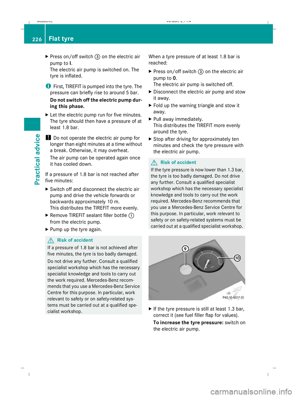
X
Press on/off switch =on the electric air
pump to I.
The electric air pump is switched on. The
tyre is inflated.
i First, TIREFIT is pumped into the tyre. The
pressure can briefly rise to around 5 bar.
Do not switch off the electric pump dur-
ing this phase.
X Let the electric pump run for five minutes.
The tyre should then have a pressure of at
least 1.8 bar.
! Do not operate the electric air pump for
longer than eight minutes at a time without
a break. Otherwise, it may overheat.
The air pump can be operated again once
it has cooled down.
If a pressure of 1.8 bar is not reached after
five minutes:
X Switch off and disconnect the electric air
pump and drive the vehicle forwards or
backwards approximately 10 m.
This distributes the TIREFIT more evenly.
X Remove TIREFIT sealant filler bottle :
from the electric pump.
X Pump up the tyre again. G
Risk of accident
If a pressure of 1.8 bar is not achieved after
five minutes, the tyre is too badly damaged.
Do not drive any further. Consult a qualified
specialist workshop which has the necessary
specialist knowledge and tools to carry out
the work required. Mercedes-Benz recom-
mends that you use a Mercedes-Benz Service
Centre for this purpose. In particular, work
relevant to safety or on safety-related sys-
tems must be carried out at a qualified spe-
cialist workshop. When a tyre pressure of at least 1.8 bar is
reached:
X
Press on/off switch =on the electric air
pump to 0.
The electric air pump is switched off.
X Disconnect the electric air pump and stow
it away.
X Fold up the warning triangle and stow it
away.
X Pull away immediately.
This distributes the TIREFIT more evenly
around the tyre.
X Stop after driving for approximately ten
minutes and check the tyre pressure with
the electric air pump. G
Risk of accident
If the tyre pressure is now lower than 1.3 bar,
the tyre is too badly damaged. Do not drive
any further. Consult a qualified specialist
workshop which has the necessary specialist
knowledge and tools to carry out the work
required. Mercedes-Benz recommends that
you use a Mercedes-Benz Service Centre for
this purpose. In particular, work relevant to
safety or on safety-related systems must be
carried out at a qualified specialist workshop. X
If the tyre pressure is still at least 1.3 bar,
correct it (see fuel filler flap for values).
To increase the tyre pressure: switch on
the electric air pump. 226 Flat tyrePractical advice
X204_AKB; 1; 5, en-GB
wobuchh,
Version: 2.11.4 2008-10-15T13:20:56+02:00 - Seite 226Dateiname: 6515_0671_02_buchblock.pdf; preflight
Page 234 of 261
X
Version 1: open flap1.
X Version 1: pull connector 3and air hose
4 out of the housing.
X Version 2: pull connector 3and the air
hose out of the housing.
X Version 1: make sure that pressure
release screw 4on the pressure gauge is
fully closed.
X Remove the cap from the valve on the tyre.
X Screw union nut 5on the air hose onto the
valve.
X Make sure on/off switch 2of the electric
air pump is set to 0.
X Insert plug 3into the cigarette lighter
socket* (Y page 138) or into a 12 V socket
in your vehicle (Y page 139).
X Make sure that the key is in posi-
tion 2(Y page 61) in the ignition lock.
X Press on/off switch 2on the electric air
pump to I.
The electric air pump is switched on. The
tyre is inflated.
X When a tyre pressure of 2.8 bar is reached,
press on/off switch 2on the electric air
pump to 0.
The electric air pump is switched off.
! Do not operate the electric air pump for
longer than eight minutes at a time without
a break. Otherwise, it may overheat.
The air pump can be operated again once
it has cooled down.
If the tyre pressure is higher than 2.8 bar:
X Version 1: open pressure release
screw 4on the pressure gauge until the
tyre pressure is correct.
X Version 2: press pressure release button
6 until the tyre pressure is correct.
X Switch off the electric air pump at on/off
switch 2, disconnect from the tyre valve
and stow away. Lowering the vehicle X
Place the ratchet ring spanner onto the
hexagon nut of the jack so that the letters
AB are visible.
X Lower the vehicle by turning the ratchet
ring spanner until the vehicle is once again
standing firmly on the ground.
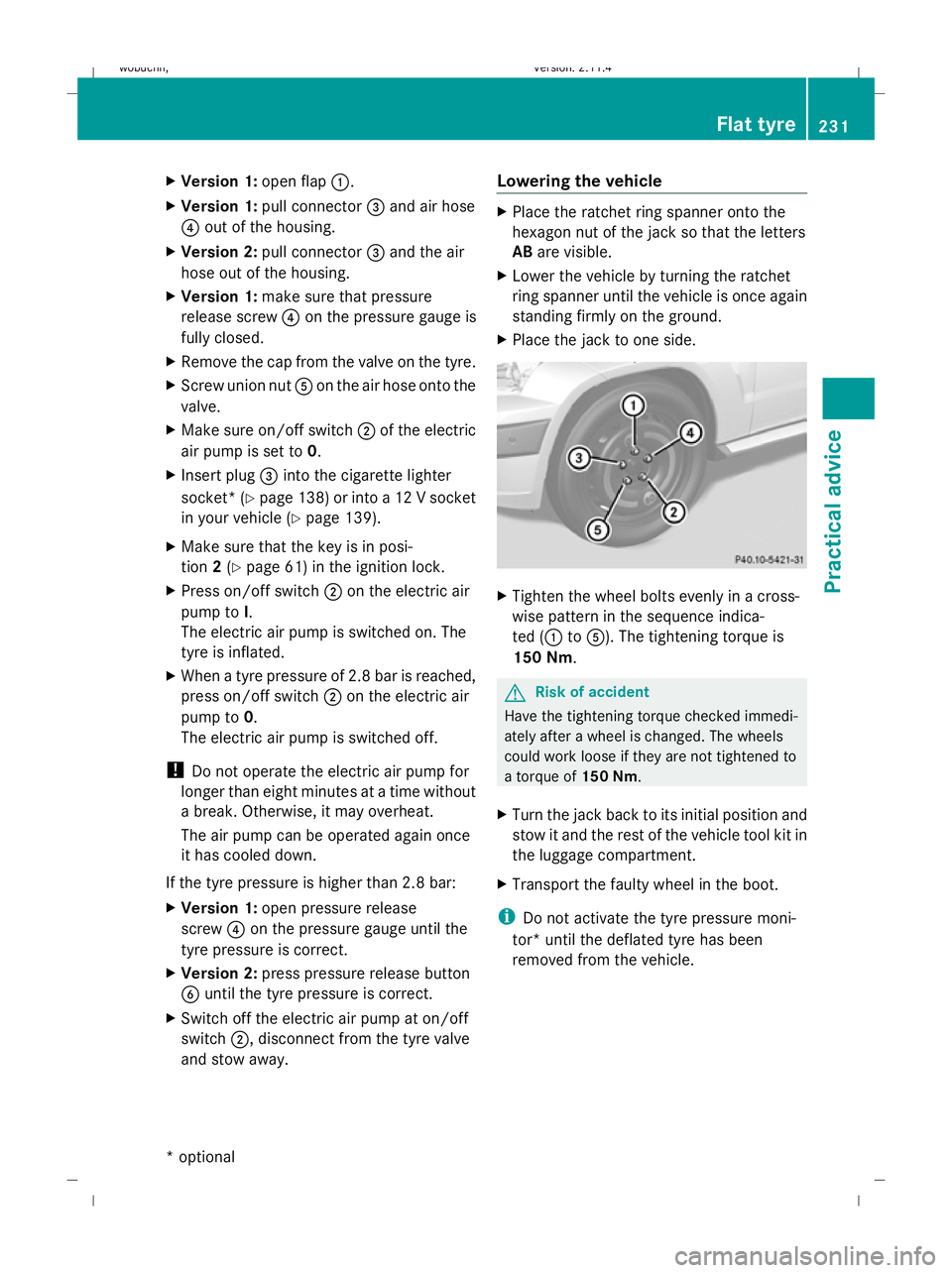
X Place the jack to one side. X
Tighten the wheel bolts evenly in a cross-
wise pattern in the sequence indica-
ted (1 to5). The tightening torque is
150 Nm. G
Risk of accident
Have the tightening torque checked immedi-
ately after a wheel is changed. The wheels
could work loose if they are not tightened to
a torque of 150 Nm.
X Turn the jack back to its initial position and
stow it and the rest of the vehicle tool kit in
the luggage compartment.
X Transport the faulty wheel in the boot.
i Do not activate the tyre pressure moni-
tor* until the deflated tyre has been
removed from the vehicle. Flat tyre
231Practical advice
* optional
X204_AKB; 1; 5, en-GB
wobuchh,
Version: 2.11.4 2008-10-15T13:20:56+02:00 - Seite 231 ZDateiname: 6515_0671_02_buchblock.pdf; preflight
Page 239 of 261
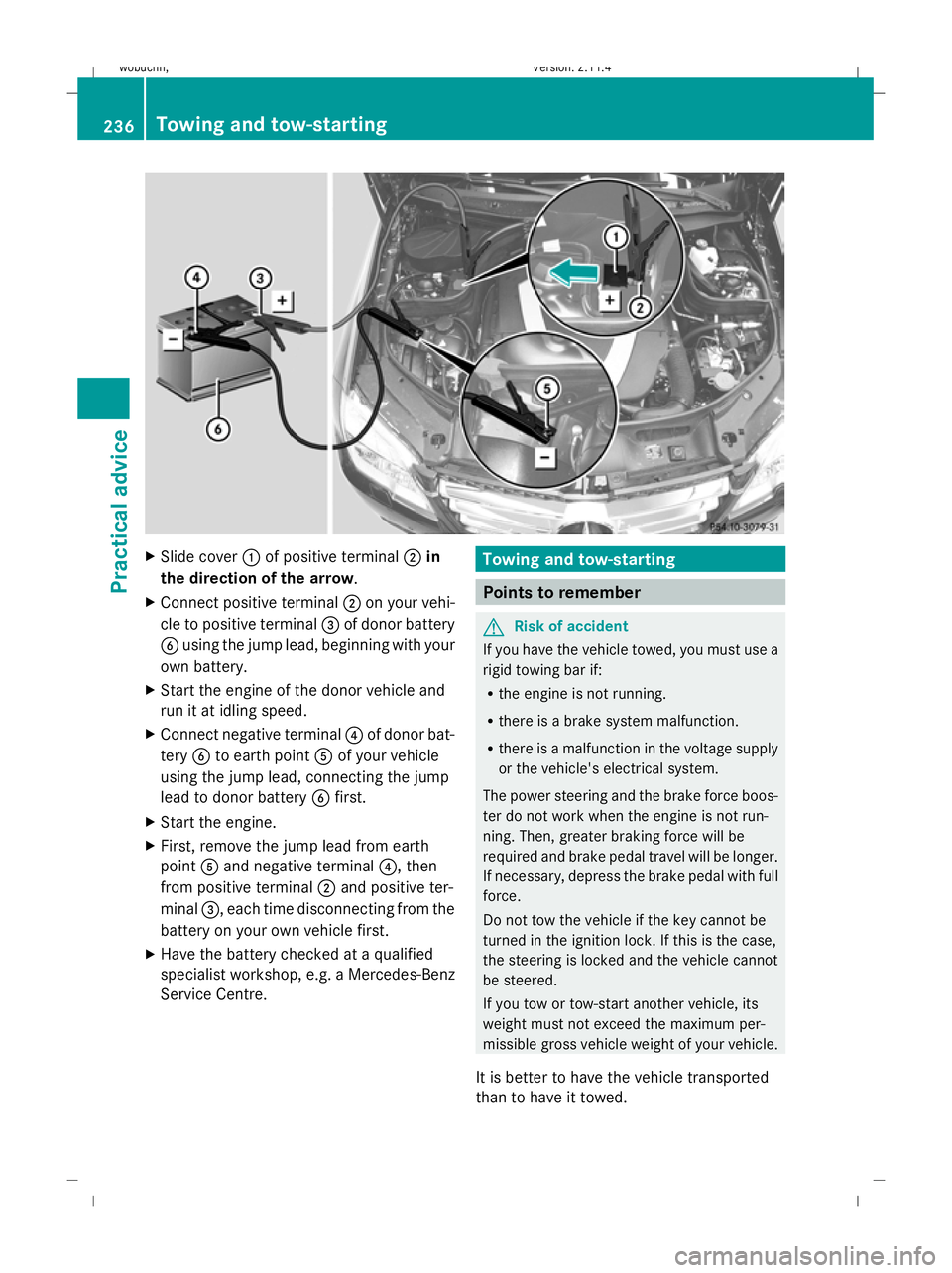
XSlide cover :of positive terminal ;in
the direction of the arrow .
X Connect positive terminal ;on your vehi-
cle to positive terminal =of donor battery
B using the jump lead, beginning with your
own battery.
X Start the engine of the donor vehicle and
run it at idling speed.
X Connect negative terminal ?of donor bat-
tery Bto earth point Aof your vehicle
using the jump lead, connecting the jump
lead to donor battery Bfirst.
X Start the engine.
X First, remove the jump lead from earth
point Aand negative terminal ?, then
from positive terminal ;and positive ter-
minal =, each time disconnecting from the
battery on your own vehicle first.
X Have the battery checked at a qualified
specialist workshop, e.g. a Mercedes-Benz
Service Centre.Towing and tow-starting
Points to remember
G Risk of accident
If you have the vehicle towed, you must use a
rigid towing bar if:
R the engine is not running.
R there is a brake system malfunction.
R there is a malfunction in the voltage supply
or the vehicle's electrical system.
The power steering and the brake force boos-
ter do not work when the engine is not run-
ning. Then, greater braking force will be
required and brake pedal travel will be longer.
If necessary, depress the brake pedal with full
force.
Do not tow the vehicle if the key cannot be
turned in the ignition lock. If this is the case,
the steering is locked and the vehicle cannot
be steered.
If you tow or tow-start another vehicle, its
weight must not exceed the maximum per-
missible gross vehicle weight of your vehicle.
It is better to have the vehicle transported
than to have it towed.
236Towing and tow-starting
Practical advice
X204_AKB; 1; 5, en-GB
wobuchh, Version: 2.11.4
2008-10-15T13:20:56+02:00 - Seite 236 Dateiname: 6515_0671_02_buchblock.pdf; preflight