2008 MERCEDES-BENZ CLS COUPE brake
[x] Cancel search: brakePage 145 of 329
Driving systems
142 Speedtronic
Speedtronic brakes automatically so that you
do not exceed the set speed. On long and
steep downhill gradients, especially if the
vehicle is laden, you must select shift range
1, 2 or 3 in good time. In this way you will
make use of the braking effect of the engine,
which relieves the load on the brake system
and prevents the brakes from overheating
and wearing too quickly. If you need addi-
tional braking, depress the brake pedal
repeatedly rather than continuously. G
Risk of accident
Never depress the brake pedal continu-
ously while the vehicle is in motion, e.g.
never cause the brakes to rub by applying
constant slight pedal pressure. This causes
the brake system to overheat, increases
the braking distance and can lead to the
brakes failing completely. G
Risk of accident
Do not change down for additional engine
braking on a slippery road surface. This
could cause the drive wheels to lose their
grip and the vehicle could skid. You can set a variable or permanent limit
speed:
R
Variable for speed limits, e.g. in built-up
areas
R Permanent for long-term speed restric-
tions, e.g. for driving on winter tyres
(Y page 144) G
Risk of accident
Speedtronic is only an aid designed to
assist driving. You are responsible for the
vehicle's speed and for braking in good
time.
i The speed indicated in the speedometer
may differ slightly from the limit speed
stored.
Variable Speedtronic With the cruise control lever you can operate
cruise control, Distronic* and variable
Speedtronic.
The LIM indicator lamp on the cruise control
lever indicates which system you have selec-
ted:
R
LIM indicator lamp off: Cruise control or Distronic* is selected
R LIM indicator lamp lit:
variable Speedtronic is selected
You can use the cruise control lever to limit
the speed to any speed above 30 km/h while
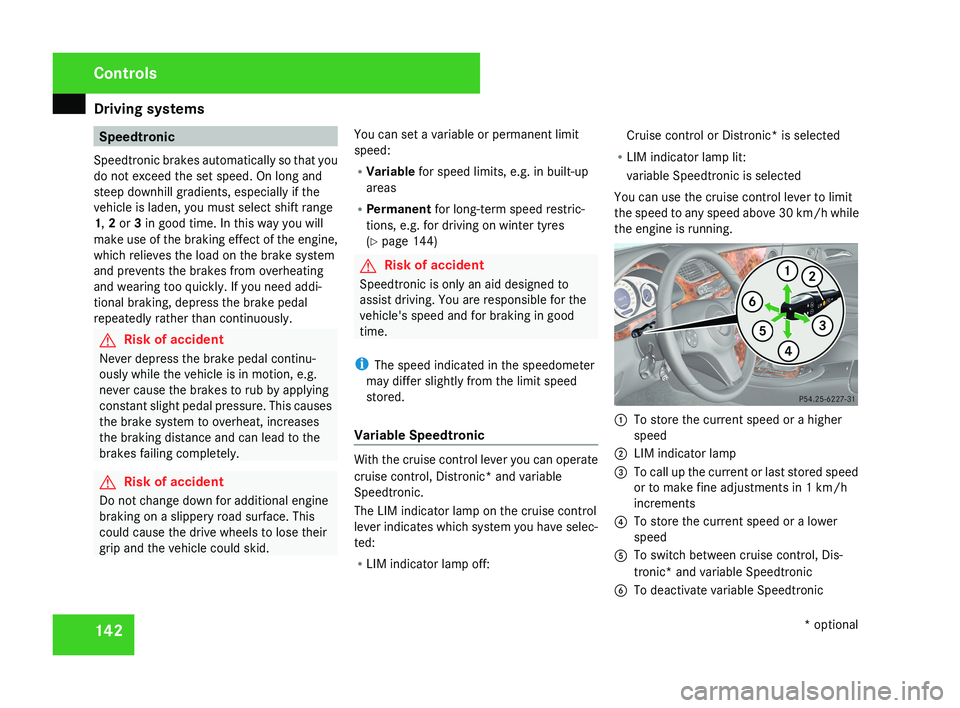
the engine is running. 1
To store the current speed or a higher
speed
2 LIM indicator lamp
3 To call up the current or last stored speed
or to make fine adjustments in 1 km/h
increments
4 To store the current speed or a lower
speed
5 To switch between cruise control, Dis-
tronic* and variable Speedtronic
6 To deactivate variable Speedtronic Controls
* optional
219_AKB; 2; 4, en-GB
mkalafa,
2007-11-13T09:28:36+01:00 - Seite 142
Page 147 of 329
Driving systems
144
Variable Speedtronic is deactivated automat-
ically when you depress the accelerator pedal
beyond the pressure point (kickdown). but
only if your current speed does not differ by
more than 20 km/h from the stored speed.
You will hear a warning tone if this is the case.
G
Risk of accident
It is not possible to deactivate variable
Speedtronic by braking.
i The last speed stored is cleared when you
switch off the engine.
Permanent Speedtronic i
Permanent Speedtronic is only available
for certain countries.
You can use the on-board computer to limit
the speed permanently to a value between
160 km/h (e.g. for driving with winter tyres)
and the maximum speed.
Shortly before the stored speed is reached, it
is shown in the multi-function display.
You cannot exceed the stored limit speed,
even if you depress the accelerator pedal
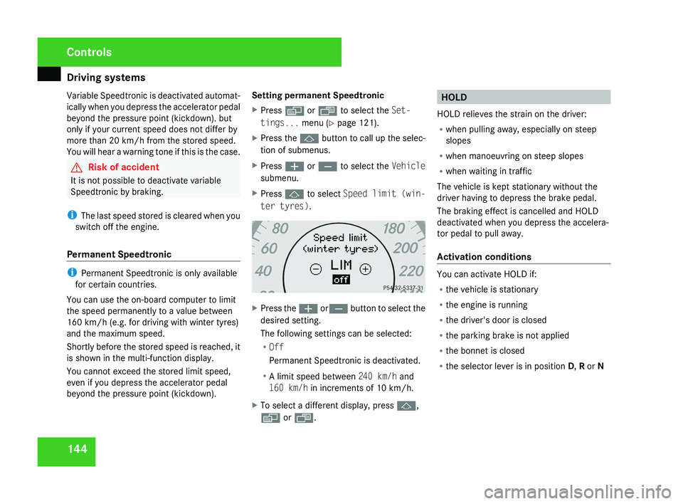
beyond the pressure point (kickdown). Setting permanent Speedtronic
X
Press è or · to select the Set-
tings... menu (Y page 121).
X Press the j button to call up the selec-
tion of submenus.
X Press æ or ç to select the Vehicle
submenu.
X Press j to select Speed limit (win-
ter tyres). X
Press the æ orç button to select the
desired setting.
The following settings can be selected:
R Off
Permanent Speedtronic is deactivated.
R A limit speed between 240 km/h and
160 km/h in increments of 10 km/h.
X To select a different display, press j,
è or ÿ. HOLD
HOLD relieves the strain on the driver:
R when pulling away, especially on steep
slopes
R when manoeuvring on steep slopes
R when waiting in traffic
The vehicle is kept stationary without the
driver having to depress the brake pedal.
The braking effect is cancelled and HOLD
deactivated when you depress the accelera-
tor pedal to pull away.
Activation conditions You can activate HOLD if:
R
the vehicle is stationary
R the engine is running
R the driver's door is closed
R the parking brake is not applied
R the bonnet is closed
R the selector lever is in position D, R or N Controls
219_AKB; 2; 4, en-GB
mkalafa,
2007-11-13T09:28:36+01:00 - Seite 144
Page 148 of 329
Driving systems
145
Activating HOLD X
Make sure that the activation conditions
are met.
X Depress the brake.
X Depress the brake again quickly until
HOLD appears in the display.
HOLD is activated. You can release the
brake pedal.
i If depressing the brake pedal the first
time does not activate HOLD, wait briefly
and then try again. G
Risk of accident
The vehicle's brakes are applied when
HOLD is activated. For this reason, deacti-
vate HOLD if the vehicle is to be set in
motion by other means (e.g. in a car wash
or by towing).
Deactivating HOLD HOLD is deactivated if:
R
you
accelerate when the selector lever is in
position D or R
R you move the selector lever to position P
R you release the brakes completely and
apply them again with a certain amount of pressure until the
HOLD message in the
multi-function display goes out G
Risk of accident
Never get out of the vehicle when HOLD is
activated.
HOLD
must never be operated or deactiva-
ted by a passenger or from outside the
vehicle.
HOLD does not replace the parking brake
and must not be used for parking.
The HOLD braking effect is cancelled and
the vehicle can start moving if:
R HOLD is deactivated by depressing the
accelerator pedal or the brake pedal
R there is a malfunction in the system or an
interruption in the power supply, e.g. bat-
tery failure
R the electrical system in the engine com-
partment, the battery or the fuses are
tampered with
R the battery is disconnected G
Risk of accident
If you wish to leave the vehicle or park it,
deactivate HOLD and secure the vehicle
against rolling away. You will see a warning message in the multi-
function display if HOLD is activated and:
R
the
driver's door is opened and you release
the seat belt
R the ignition is switched off
R the bonnet is opened
Selector lever in park position
X Move the selector lever to P
to prevent the
vehicle from rolling away.
HOLD is deactivated. The warning message
in the multi-function display goes out.
A horn will also sound at regular intervals if
HOLD is activated and you:
R stop
the engine and open the driver's door
R open the bonnet
The horn draws your attention to the fact that
the vehicle has been parked while HOLD is
still activated. The sound becomes louder if
you attempt to lock the vehicle. The vehicle
is not locked until HOLD is deactivated.
i If the ignition has been switched off, the
engine cannot be restarted until HOLD is
deactivated.
If there is a fault in the system or power supply
while HOLD is activated, the Brake immedi-
ately message appears in the multi-function Controls
219_AKB; 2; 4, en-GB
mkalafa,
2007-11-13T09:28:36+01:00 - Seite 145 Z
Page 149 of 329
Driving systems
146
display. Immediately depress the brake firmly
until the warning message disappears from
the multi-function display or move the selec-
tor lever to
P. This deactivates HOLD. AIRMATIC DC*
Vehicle level Your vehicle automatically adjusts its ride
height to reduce petrol consumption and
improve driving safety.
The following vehicle levels are possible:
R
Normal
R Raised
R Lowered
The "Normal" and "Raised" vehicle levels can
be set manually.
The "Lowered" vehicle level is set automati-
cally:
R at speeds above 140 km/h
R if you have selected "Sports tuning I or
II" ( Y page 147)
R if you have selected "Comfort tun-
ing" (Y page 147) and then lock the vehicle within 60 seconds of the engine being
switched off G
Risk of injury
If you have selected “Comfort tuning”, the
vehicle will be lowered if you lock it within
60 seconds of the engine being switched
off. Make sure, therefore, that nobody is in
the vicinity of the wheel housing or under
the vehicle when you lock the vehicle. Oth-
erwise, limbs could become trapped.
! If you have selected “Comfort tuning”,
the vehicle will be lowered if you lock it
within 60 seconds of the engine being
switched off. Make sure when parking that
you stop your vehicle so that it does not
make contact with the kerb as it descends.
Your vehicle could otherwise be damaged.
Setting the vehicle level manually
Select the "Normal" setting for normal road
surfaces and "Raised" for driving with snow
chains or on particularly poor road surfaces. G
Risk of injury
Make sure that nobody is in the vicinity of
the wheel housing or under the vehicle
while lowering the vehicle when it is sta- tionary. Otherwise, limbs could become
trapped.
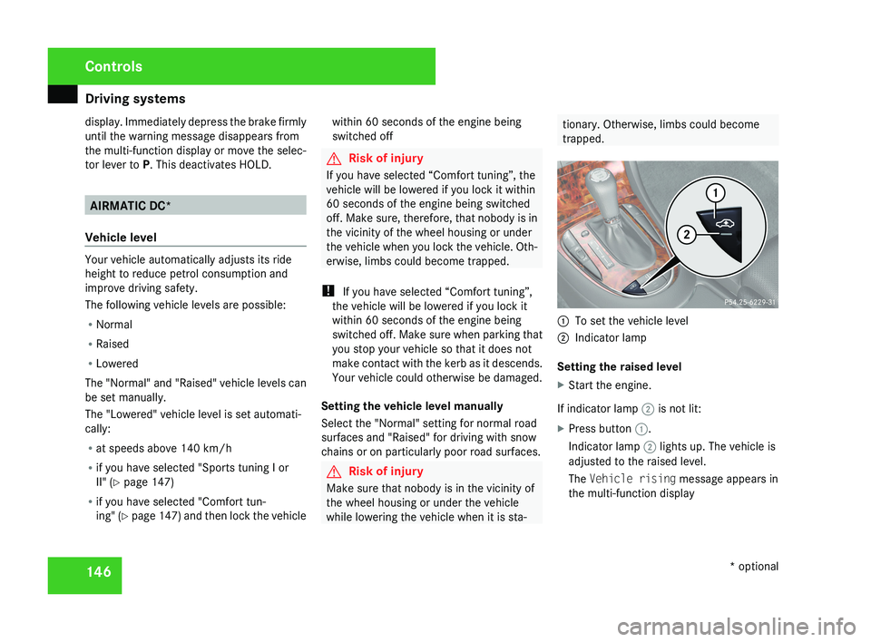
1
To set the vehicle level
2 Indicator lamp
Setting the raised level
X Start the engine.
If indicator lamp 2 is not lit:
X Press button 1.
Indicator lamp 2 lights up. The vehicle is
adjusted to the raised level.
The Vehicle rising message appears in
the multi-function display Controls
* optional
219_AKB; 2; 4, en-GB
mkalafa,
2007-11-13T09:28:36+01:00 - Seite 146
Page 151 of 329
Driving systems
148 Parktronic*
G
Risk of accident
Parktronic is only an aid and may not detect
all obstacles. It does not relieve you of the
responsibility to pay attention.
You are always responsible for safety and
must continue to pay attention to your
immediate surroundings when parking and
manoeuvring. You could otherwise endan-
ger yourself and others. G
Risk of injury
Make sure that no persons or animals are
in the manoeuvring range. Otherwise, they
could be injured.
Parktronic is an electronic parking aid. It indi-
cates visually and audibly the distance
between your vehicle and an object.
Parktronic is automatically activated when
you switch on the ignition and release the
parking brake.
Parktronic is deactivated at speeds above
18 km/h. It is reactivated at lower speeds.
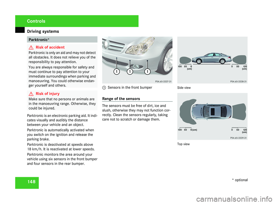
Parktronic monitors the area around your
vehicle using six sensors in the front bumper
and four sensors in the rear bumper.1 Sensors in the front bumper
Range of the sensors
The sensors must be free of dirt, ice and
slush, otherwise they may not function cor-
rectly. Clean the sensors regularly, taking
care not to scratch or damage them.
Side view
Top view
Controls
* optional
219_AKB; 2; 4, en-GB
mkalafa,
2007-11-13T09:28:36+01:00 - Seite 148
Page 152 of 329
Driving systems
149
Front sensors Centre Approximately 100 cm
Corners Approximately 60 cm
Rear sensors
Centre Approximately 120 cm
Corners Approximately 80 cm
!
Pay particular attention to objects above
or below the sensors when parking, such
as flower pots or trailer towbars. Parktronic
does not detect such objects when they are
in the immediate vicinity of the vehicle. You
could damage the vehicle or the objects.
Ultrasonic sources such as an automatic
car wash, a lorry's compressed-air brakes
or a pneumatic drill could cause Parktronic
to malfunction.
Minimum distance Centre Approximately 20 cm
Corners Approximately 15 cm If there is an obstacle within this range, all
warning displays light up and a tone sounds.
If the distance falls below the minimum clear-
ance, it may no longer be shown.
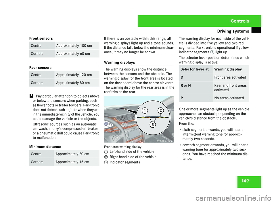
Warning displays
The warning displays show the distance
between the sensors and the obstacle. The
warning display for the front area is located
on the dashboard above the centre air vents.
The warning display for the rear area is in the
roof trim at the rear.
Front area warning display
1
Left-hand side of the vehicle
2 Right-hand side of the vehicle
3 Indicator segments The warning display for each side of the vehi-
cle is divided into five yellow and two red
segments. Parktronic is operational if yellow
indicator segments
3 light up.
The selector lever position determines which
warning display is active: Selector lever at Warning display
D Front area activated
R or N Rear and front areas
activated
P No areas activated
One or more segments light up as the vehicle
approaches an obstacle, depending on the
vehicle's distance from the obstacle.
From the:
R
sixth segment onwards, you will hear an
intermittent warning tone for approxi-
mately two seconds.
R seventh segment onwards, you will hear a
warning tone for approximately two sec-
onds. You have reached the minimum dis-
tance. Controls
219_AKB; 2; 4, en-GB
mkalafa,
2007-11-13T09:28:36+01:00 - Seite 149
Page 175 of 329
Loading and stowing
172 Loading and stowing
Cup holder
G
Risk of injury
Keep the cup holder closed while the vehi-
cle is in motion. Otherwise, vehicle occu-
pants could be injured by objects being
thrown around if you:
R brake sharply
R change direction suddenly
R are involved in an accident
Only use the cup holders for containers of
a suitable size and which have lids. Other-
wise, the drinks could spill.
Cup holders should not be used for hot
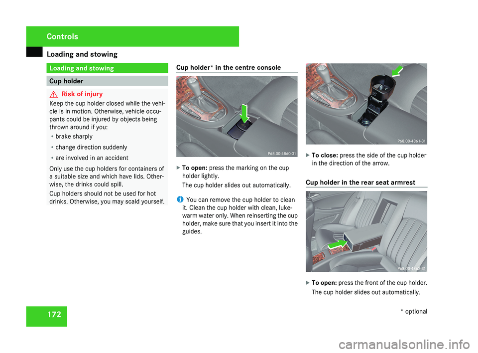
drinks. Otherwise, you may scald yourself. Cup holder* in the centre console X
To open: press the marking on the cup
holder lightly.
The cup holder slides out automatically.
i You can remove the cup holder to clean
it. Clean the cup holder with clean, luke-
warm water only. When reinserting the cup
holder, make sure that you insert it into the
guides. X
To close: press the side of the cup holder
in the direction of the arrow.
Cup holder in the rear seat armrest X
To open: press the front of the cup holder.
The cup holder slides out automatically. Controls
* optional
219_AKB; 2; 4, en-GB
mkalafa,
2007-11-13T09:28:36+01:00 - Seite 172
Page 180 of 329
Loading and stowing
177Stowage compartments
G
Risk of injury
The stowage compartments must be closed
when items are stored in them. Luggage
nets are not designed to secure heavy
items of luggage.
You or other vehicle occupants could be
injured by objects being thrown around if
you:
R brake sharply
R change direction suddenly
R have an accident
Sharp-edged and fragile objects must not
be carried in the luggage net.
Do not carry hard objects in the ruffled
pockets. Objects must not protrude over
the top of the ruffled pockets.
i You will find an overview of the stowage
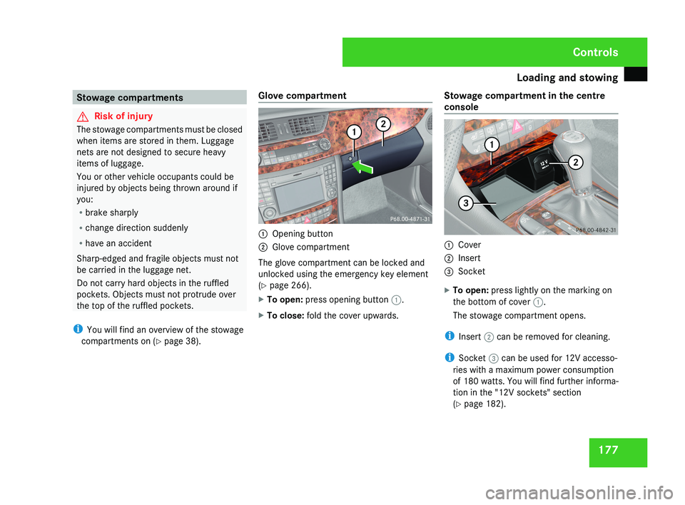
compartments on (Y page 38). Glove compartment 1
Opening button
2 Glove compartment
The glove compartment can be locked and
unlocked using the emergency key element
(Y page 266).
X To open: press opening button 1.
X To close: fold the cover upwards. Stowage compartment in the centre
console 1
Cover
2 Insert
3 Socket
X To open: press lightly on the marking on
the bottom of cover 1.
The stowage compartment opens.
i Insert 2 can be removed for cleaning.
i Socket 3 can be used for 12V accesso-
ries with a maximum power consumption
of 180 watts. You will find further informa-
tion in the "12V sockets" section
(Y page 182). Controls
219_AKB; 2; 4, en-GB
mkalafa,
2007-11-13T09:28:36+01:00 - Seite 177