2008 MERCEDES-BENZ CLS COUPE spare wheel
[x] Cancel search: spare wheelPage 208 of 329
Winter driving
205required. Mercedes-Benz recommends
that you use a Mercedes-Benz Service
Centre
for this purpose. In particular, work
relevant to safety or on safety-related sys-
tems must be carried out at a qualified
specialist workshop. Snow chains
For safety reasons, Mercedes-Benz recom-
mends that you only use snow chains which
have
been specially approved for your vehicle
by Mercedes-Benz or are of a corresponding
standard of quality.
! Information about the use of snow chain-
compatible AMG winter tyres is applicable
for AMG tyres. Use of snow chains is only
permissible with these tyres.
If you intend to fit snow chains, please bear
the following points in mind: R
Snow
chains cannot be fitted to all wheel/
tyre combinations.
R Snow chains must not be fitted to emer-
gency spare wheels, e.g. the "Minispare" or
collapsible emergency spare wheel.
R Fit snow chains to both rear wheels. Com-
ply with the manufacturer's installation
instructions.
! If snow chains are fitted to the front
wheels, they may come into contact with
the bodywork and axle components when
the vehicle is in motion and damage the
tyre or the vehicle.
On vehicles with AIRMATIC DC*, you must
only drive at raised vehicle level if snow
chains have been fitted (Y page 146).
Do not exceed the maximum permissible
speed of 50 km/h.
i You may wish to deactivate ESP ®
when
pulling away with snow chains fitted
(Y page 59). This way you can allow the
wheels to spin in a controlled manner, ach-
ieving an increased driving force (cutting
action). Winter driving
G
Risk of accident
Do not shift down for additional engine
braking on a slippery road surface. This
could cause the drive wheels to lose their
grip and the vehicle could skid.
You
should drive particularly carefully on slip-
pery road surfaces. Avoid sudden accelera-
tion, steering and braking manoeuvres.
If the vehicle threatens to skid or cannot be
stopped when moving at low speed:
X Shift the selector lever to N.
X Try to bring the vehicle under control using
corrective steering. Operation
219_AKB; 2; 4, en-GB
mkalafa,
2007-11-13T09:28:36+01:00 - Seite 205
Page 220 of 329
Where will I find...?
217Fire extinguisher*
i Have the fire extinguisher refilled after
each use and checked every one or two
years. Otherwise, it may fail in an emer-
gency.
Observe the legal requirements in all coun-
tries concerned.
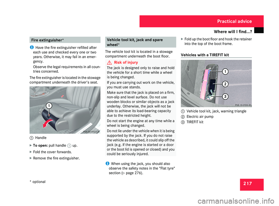
The fire extinguisher is located in the stowage
compartment underneath the driver's seat.1 Handle
X To open: pull handle 1 up.
X Fold the cover forwards.
X Remove the fire extinguisher.
Vehicle tool kit, jack and spare
wheel*
The vehicle tool kit is located in a stowage
compartment underneath the boot floor.
G Risk of injury
The jack is designed only to raise and hold
the vehicle for a short time while a wheel
is being changed.
If you are carrying out work on the vehicle,
you must use stands.
Make sure that the jack is placed on a firm,
non-slip and level surface. Do not use
wooden blocks or similar objects as a jack
underlay. Otherwise, the jack will not be
able to achieve its load-bearing capacity
due to the restricted height.
Do not start the engine at any time while a
wheel is being changed.
Do not lie under the vehicle when it is being
supported by the jack. If you do not raise
the vehicle as described, it could slip off the
jack (e.g. if the engine is started or a door
or the boot lid is opened or closed) and you
could be seriously injured.
i When using the jack, you should also
observe the safety notes in the "Flat tyre"
section ( Y page 276). X
Fold up the boot floor and hook the retainer
into the top of the boot frame.
Vehicles with a TIREFIT kit
1 Vehicle tool kit, jack, warning triangle
2 Electric air pump
3 TIREFIT kit
Practical advice
* optional
219_AKB; 2; 4, en-GB
mkalafa,
2007-11-13T09:28:36+01:00 - Seite 217
Page 221 of 329
Where will I find...?
218
Vehicles with "Minispare" emergency
spare wheel*/collapsible emergency
spare wheel* or a spare wheel
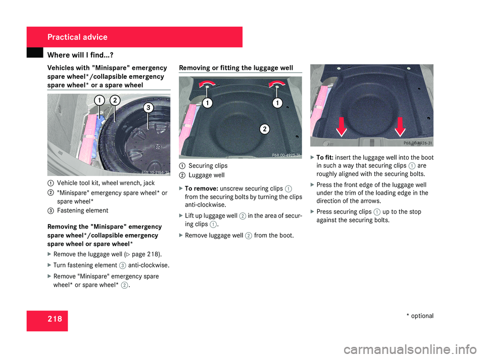
1
Vehicle tool kit, wheel wrench, jack
2 "Minispare" emergency spare wheel* or
spare wheel*
3 Fastening element
Removing the "Minispare" emergency
spare wheel*/collapsible emergency
spare wheel or spare wheel*
X Remove the luggage well (Y page 218).
X Turn fastening element 3 anti-clockwise.
X Remove "Minispare" emergency spare
wheel* or spare wheel* 2.Removing or fitting the luggage well
1
Securing clips
2 Luggage well
X To remove: unscrew securing clips 1
from the securing bolts by turning the clips
anti-clockwise.
X Lift up luggage well 2 in the area of secur-
ing clips 1.
X Remove luggage well 2 from the boot. X
To fit: insert the luggage well into the boot
in such a way that securing clips 1 are
roughly aligned with the securing bolts.
X Press the front edge of the luggage well
under the trim of the loading edge in the
direction of the arrows.
X Press securing clips 1 up to the stop
against the securing bolts. Practical advice
* optional
219_AKB; 2; 4, en-GB
mkalafa,
2007-11-13T09:28:36+01:00 - Seite 218
Page 228 of 329
Display messages
225Display messages Possible cause/consequence Possible solution
Tyre press.
mon. Wheel sensor miss-
ing
The tyre pressure monitor* is not receiv-
ing a signal from at least one wheel
because a wheel has been fitted which
does not have suitable sensors (e.g. the
spare wheel). Or there is a malfunction in
at least one wheel sensor.
A line is displayed in the multi-function
display for the tyre concerned instead of
the tyre pressure value. X
Have the tyre pressure monitor* and wheels
checked at a qualified specialist workshop.
Once
wheels with suitable wheel sensors have
been fitted again, the tyre pressures are dis-
played in the multi-function display after driv-
ing for a few minutes. Tyre pressure
monitor currently unavail-
able
The tyre pressure monitor* is temporarily
deactivated. The voltage of the vehicle's
electrical
system is too low or radio inter-
ference prevents the reception of sensor
signals. X
Drive on.
Once
the causes have been eliminated, the tyre
pressure monitor* automatically reactivates
after a few minutes of driving. Practical advice
* optional
219_AKB; 2; 4, en-GB
mkalafa,
2007-11-13T09:28:36+01:00 - Seite 225 Z
Page 279 of 329
Flat tyre
276 Fitting
X Slide the new wiper blade into the retainer
on the wiper arm in the opposite direction
to the arrow.
X Turn the wiper blade parallel to the wiper
arm.
X Fold the wiper arm back onto the wind-
screen. Flat tyre
Your vehicle may be equipped with:
R a TIREFIT kit (Y page 217)
R a "Minispare" emergency spare
wheel*
(Y page 218)
R a collapsible emergency spare
wheel* (Y page 218)
R a spare wheel* (Y page 218)
R the MOExtended run-flat sys-
tem* (Y page 287) Preparing the vehicle
i Vehicle preparation is not necessary on
vehicles with MOE tyres*.
X Stop your vehicle as far away from traffic
as possible on solid, non-slippery, level
ground.
X Switch on the hazard warning lamps.
X Firmly depress the parking brake.
X Move the selector lever to P. X
All occupants must get out of the vehicle.
Make
sure that they are not endangered as
they do so.
X Make sure that no one is near the danger
area whilst a wheel is being changed. Any-
one who is not directly assisting in the
wheel change should, for example, stand
behind the barrier.
X Switch off the engine.
X Remove the key from the ignition lock.
X Place the warning triangle ( Y page 216) or
warning lamps at a suitable distance.
Observe legal requirements. G
Risk of injury
The jack is designed only to raise the vehi-
cle for a short time while a wheel is being
changed.
If you intend to work under the vehicle, it
must be placed on stands.
Make
sure that the jack is placed on a firm,
non-slip, level surface. Do not use wooden
blocks or similar as jacking supports. Oth-
erwise, the jack will not be able to achieve
its load-bearing capacity due to the restric-
ted height. Practical advice
* optional
219_AKB; 2; 4, en-GB
mkalafa,
2007-11-13T09:28:36+01:00 - Seite 276
Page 285 of 329
Flat tyre
282 G
Risk of accident
If the tyre pressure is now lower than
1.3 bar, the tyre is too badly damaged. Do
not drive any further. Consult a qualified
specialist workshop which has the neces-
sary specialist knowledge and tools to carry
out the work required. Mercedes-Benz rec-
ommends that you use a Mercedes-Benz
Service Centre for this purpose. In particu-
lar, work relevant to safety or on safety-
related systems must be carried out at a
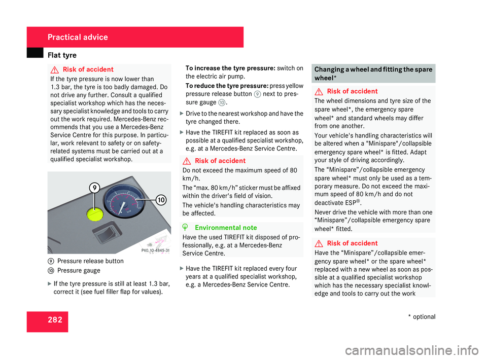
qualified specialist workshop.9 Pressure release button
a Pressure gauge
X If the tyre pressure is still at least 1.3 bar,
correct it (see fuel filler flap for values). To increase the tyre pressure:
switch on
the electric air pump.
To reduce the tyre pressure: press yellow
pressure release button 9 next to pres-
sure gauge a.
X Drive to the nearest workshop and have the
tyre changed there.
X Have the TIREFIT kit replaced as soon as
possible at a qualified specialist workshop,
e.g. at a Mercedes-Benz Service Centre.
G Risk of accident
Do not exceed the maximum speed of 80
km/h.
The “max. 80 km/h” sticker must be affixed
within the driver's field of vision.
The vehicle's handling characteristics may
be affected.
H Environmental note
Have the used TIREFIT kit disposed of pro-
fessionally, e.g. at a Mercedes-Benz
Service Centre.
X Have the TIREFIT kit replaced every four
years at a qualified specialist workshop,
e.g. a Mercedes-Benz Service Centre.
Changing a wheel and fitting the spare
wheel*
G Risk of accident
The wheel dimensions and tyre size of the
spare wheel*, the emergency spare
wheel* and standard wheels may differ
from one another.
Your vehicle's handling characteristics will
be altered when a "Minispare"/collapsible
emergency spare wheel* is fitted. Adapt
your style of driving accordingly.
The “Minispare”/collapsible emergency
spare wheel* must only be used as a tem-
porary measure. Do not exceed the maxi-
mum speed of 80 km/h and do not
deactivate ESP ®
.
Never drive the vehicle with more than one
“Minispare”/collapsible emergency spare
wheel* fitted.
G Risk of accident
Have the “Minispare”/collapsible emer-
gency spare wheel* or the spare wheel*
replaced with a new wheel as soon as pos-
sible at a qualified specialist workshop
which has the necessary specialist knowl-
edge and tools to carry out the work
Practical advice
* optional
219_AKB; 2; 4, en-GB
mkalafa,
2007-11-13T09:28:36+01:00 - Seite 282
Page 286 of 329
Flat tyre
283required. Mercedes-Benz recommends
that you use a Mercedes-Benz Service
Centre for this purpose. In particular, work
relevant to safety or on safety-related sys-
tems must be carried out at a qualified
specialist workshop.
Preparing the vehicle X
Prepare the vehicle as described
(Y page 276).
X Place the wheels in the straight-ahead posi-
tion.
X Take the following from the stowage well
beneath the boot floor:
R
the "Minispare"/collapsible emergency
spare wheel* or the spare wheel*
R the vehicle tool kit
R the wheel chock
R the jack
X Secure the vehicle to prevent it from rolling
away.
On level ground: place chocks or similar
under the front and rear of the wheel that
is diagonally opposite the wheel you wish
to change. X
On downhill gradients: place chocks or
similar under both wheels of the other axle.
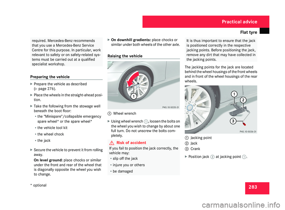
Raising the vehicle 1
Wheel wrench
X Using wheel wrench 1, loosen the bolts on
the wheel you wish to change by about one
full turn. Do not unscrew the bolts com-
pletely. G
Risk of accident
If you fail to position the jack correctly, the
vehicle may:
R slip off the jack
R injure you or others
R be damaged It is thus important to ensure that the jack
is positioned correctly in the respective
jacking points. Before positioning the jack,
remove any dirt that may have collected in
the jacking points.
The jacking points for the jack are located
behind the wheel housings of the front wheels
and in front of the wheel housings of the rear
wheels. 1
Jacking point
2 Jack
3 Crank
X Position jack 2 at jacking point 1. Practical advice
* optional
219_AKB; 2; 4, en-GB
mkalafa,
2007-11-13T09:28:36+01:00 - Seite 283
Page 288 of 329
Flat tyre
2851
Wheel bolts for all wheels supplied by the
factory
X Clean the wheel and wheel hub contact
surfaces.
XPlace the "Minispare"/collapsible emer-
gency spare wheel* or the spare wheel
onto the centring pin and push it on.
XTighten the wheel bolts until they are fin-
ger-tight.
X Unscrew the centring pin.
X Tighten the last wheel bolt until it is finger-
tight.
Inflating the collapsible emergency
spare wheel* with the electric air pump
G Risk of accident
Pump up the collapsible emergency spare
wheel before lowering the vehicle, as you
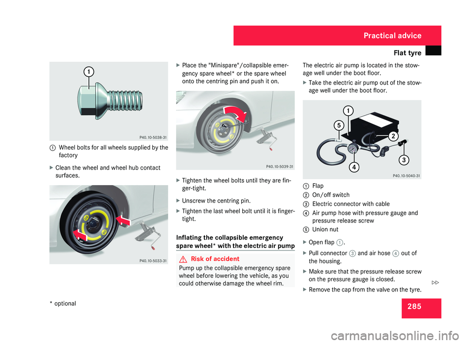
could otherwise damage the wheel rim. The electric air pump is located in the stow-
age well under the boot floor.
X
Take the electric air pump out of the stow-
age well under the boot floor.
1 Flap
2 On/off switch
3 Electric connector with cable
4 Air pump hose with pressure gauge and
pressure release screw
5 Union nut
X Open flap 1.
X Pull connector 3 and air hose 4 out of
the housing.
X Make sure that the pressure release screw
on the pressure gauge is closed.
X Remove the cap from the valve on the tyre.
Practical advice
* optional
219_AKB; 2; 4, en-GB
mkalafa,
2007-11-13T09:28:36+01:00 - Seite 285
Z