2008 INFINITI QX56 clock
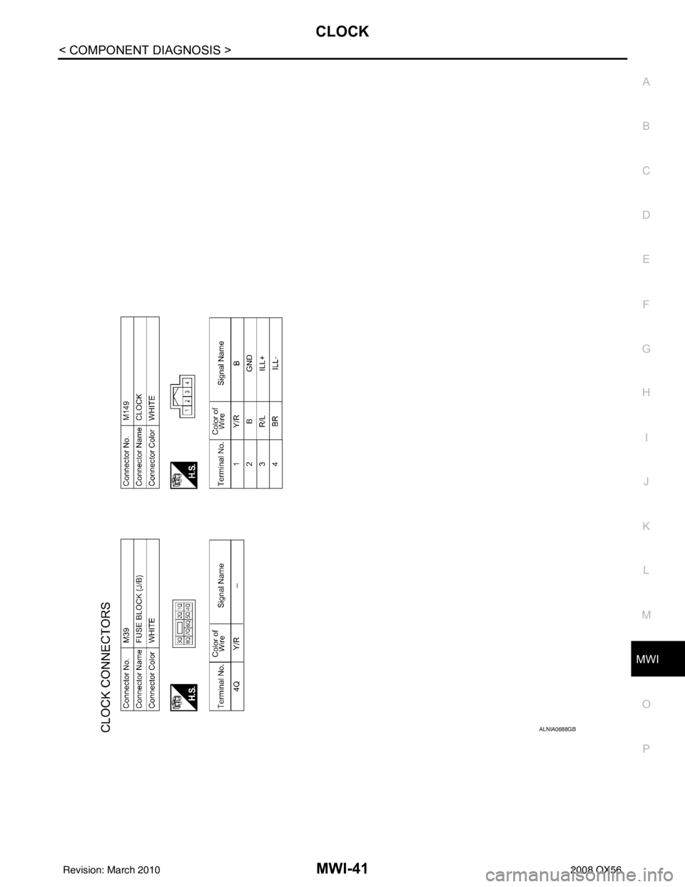
[x] Cancel search: clockPage 2686 of 4083
MWI
CLOCKMWI-41
< COMPONENT DIAGNOSIS >
C
DE
F
G H
I
J
K L
M B A
O P
ALNIA0688GB
Revision: March 2010 2008 QX56
Page 2722 of 4083
MWI
CLOCKMWI-77
< ON-VEHICLE REPAIR >
C
DE
F
G H
I
J
K L
M B A
O P
CLOCK
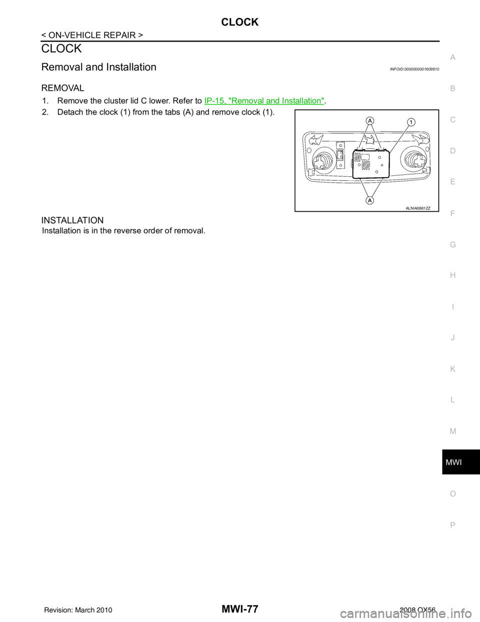
Removal and InstallationINFOID:0000000001609810
REMOVAL
1. Remove the cluster lid C lower. Refer to IP-15, "Removal and Installation".
2. Detach the clock (1) from the tabs (A) and remove clock (1).
INSTALLATION
Installation is in the reverse order of removal.
ALNIA0661ZZ
Revision: March 2010 2008 QX56
Page 2809 of 4083

PG-42
< COMPONENT DIAGNOSIS >
HARNESS
A3 M6 W/10 : To E10A2 M92 B/6 : Power liftgate switch
A2 M7 B/5 : Passenger select unlock relay D1 M93 W/24 : Display unit
A3 M8 W/16 : To D2 A2 M95 W/6 : Rear power vent window switch
A2 M9 BR/24 : To D1 A2 M96 BR/6 : Pedal adjusting switch
A3 M10 Y/4 : To E29 C2 M98 W/16 : A/C and AV switch assembly
A3 M11 B/1 : Parking brake switch C3 M99 BR/2 : Foot lamp LH
C3 M12 GR/6 : Key switch and ignition knob switch F4 M100 BR/2 : Foot lamp RH
D3 M13 BR/2 : Front passenger air bag OFF indicator F4 M101 Y/2 : Driver air bag module
B3 M15 W/4 : Steering lock solenoid F4 M102 GR/8 : Combination switch (spiral cable)
A2 M16 GR/6 : ADP steering switch F4 M103 Y/2 : Driver air bag module
B2 M17 W/8 : Steering angle sensor E3 M104 W/4 : Aux jack
C2 M18 W/40 : BCM (body control module) F2 M105 Y/2 : Front passenger air bag module
C2 M19 W/15 : BCM (body control module) F2 M106 O/2 : Front passenger air bag module
C2 M20 B/15 : BCM (body control module) F3 M107 B/5 : Front blower relay
C3 M22 W/16 : Data link connector D5 M108 B/6 : Yaw rate/ side/ decel G sensor
B1 M23 W/12 : Combination meter A1 M109 BR/2 : Front tweeter LH
C1 M24 W/40 : Combination meter D2 M110 BR/2 : Center speaker
F2 M25 B/4 : Remote keyless entry receiver F2 M111 BR/2 : Front tweeter LH
B2 M26 W/6 : Ignition switch C2M112 BR/14 : BO SE speaker amp.
A2 M27 B/2 : Diode-3 C2 M113 BR/23 : BOSE speaker amp.
B2 M28 W/16 : Combination switch B3 M114 W/2 : Heated steering wheel
B2 M29 Y/6 : Combination switch (spiral cable) A2 M116 GR/8 : Sonar system OFF switch
B3 M30 GR/8 : Combination switch (spiral cable) B1 M118 BR/2 : Front sonar buzzer
G4 M31 SMJ : To E152 F2 M120 W/4 : Remote keyless entry receiver
C3 M32 W/4 : In-vehicle sensor F4 M122 W/4 : Variable blower control (front)
B3 M33 W/32 : Automatic drive position control unit C3 M123 W/2 : Tire pressure warning check connector
B3 M34 W/16 : Automatic drive position control unit D2 M124 GR/3 : AV control unit
C5 M35 Y/28 : Air bag diagnosis sensor unit D2 M125 B/1 : Satellite radio antenna
G4 M36 SMJ : To B149 C3 M129 V/1 : Satellite radio tuner
G3 M37 B/1 : Fuse block (J/B) D2 M139 B/2 : Diode-1
G3 M38 B/2 : Fuse block (J/B) D1 M140 B/2 : Diode-2
D3 M39 W/8 : Fuse block (J/B) C2 M141 GR/8 : 4WD shift switch
A3 M40 SMJ : To B69 E1 M142 B/6 : Mode door motor (front)
D2 M42 W/20 : AV control unit E3 M143 B/6 : Air mix door motor (passenger)
D2 M43 W/12 : AV control unit C1 M144 B/6 : Defroster door motor
D2 M44 W/32 : AV control unit E3 M146 GR/2 : Intake sensor
D3 M45 W/40 : AV control unit D3 M147B/6 : Air mix doo r motor (driver)
D2 M46 W/32 : AV control unit D2 M148 W/4 : Headlamp aiming switch
D2 M49 L/26 : A/C auto AMP D3 M149 W/4 : Clock
D2 M50 B/26 : A/C auto AMP B1 M150 W/2 : Ignition keyhole illumination
B3 M51 L/4 : Trailer tow relay 1 G4 M157 W/20 : To B161
B2 M52 W/2 : Combination switch (spiral cable) A3 M158 W/10 : To D3
D3 M53 B/3 : Front power socket LH Console sub-harness
E3 M54 B/3 : Front power socket RH (for cigarette
lighter) D4 M201 W/16 : To M56
D2 M55 W/4 : Hazard switch D4 M202 BR/24 : To M64
Revision: March 2010 2008 QX56
Page 2896 of 4083
BCM (BODY CONTROL MODULE)PWC-55
< ECU DIAGNOSIS >
C
DE
F
G H
I
J
L
M A
B
PWC
N
O P
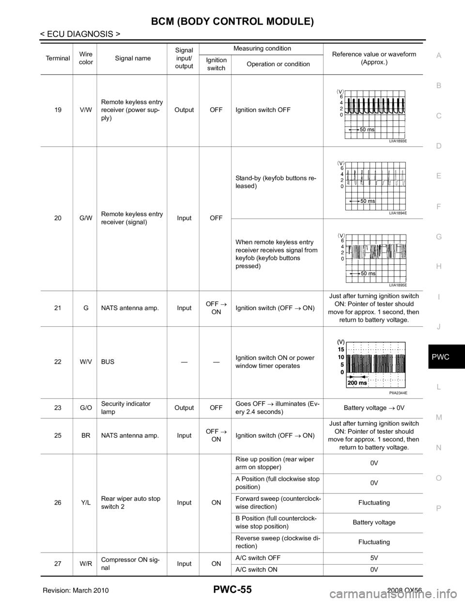
19 V/W Remote keyless entry
receiver (power sup-
ply) Output OFF Ignition switch OFF
20 G/W Remote keyless entry
receiver (signal) Input OFFStand-by (keyfob buttons re-
leased)
When remote keyless entry
receiver receives signal from
keyfob (keyfob buttons
pressed)
21 G NATS antenna amp. Input OFF
→
ON Ignition switch (OFF → ON) Just after turning ignition switch
ON: Pointer of tester should
move for approx. 1 second, then return to battery voltage.
22 W/V BUS — —Ignition switch ON or power
window timer operates
23 G/O Security indicator
lamp Output OFF
Goes OFF
→ illuminates (Ev-
ery 2.4 seconds) Battery voltage
→ 0V
25 BR NATS antenna amp. Input OFF
→
ON Ignition switch (OFF → ON) Just after turning ignition switch
ON: Pointer of tester should
move for approx. 1 second, then return to battery voltage.
26 Y/L Rear wiper auto stop
switch 2 Input ONRise up position (rear wiper
arm on stopper)
0V
A Position (full clockwise stop
position) 0V
Forward sweep (counterclock-
wise direction) Fluctuating
B Position (full counterclock-
wise stop position) Battery voltage
Reverse sweep (clockwise di-
rection) Fluctuating
27 W/R Compressor ON sig-
nal Input ONA/C switch OFF
5V
A/C switch ON 0V
Te r m i n a l
Wire
color Signal name Signal
input/
output Measuring condition
Reference value or waveform
(Approx.)
Ignition
switch Operation or condition
LIIA1893E
LIIA1894E
LIIA1895E
PIIA2344E
Revision: March 2010
2008 QX56
Page 2898 of 4083
BCM (BODY CONTROL MODULE)PWC-57
< ECU DIAGNOSIS >
C
DE
F
G H
I
J
L
M A
B
PWC
N
O P
44 O Rear wiper auto stop
switch 1 Input ONRise up position (rear wiper
arm on stopper)
0V
A Position (full clockwise stop
position) Battery voltage
Forward sweep (counterclock-
wise direction) Fluctuating
B Position (full counterclock-
wise stop position) 0V
Reverse sweep (clockwise di-
rection) Fluctuating
47 SB Front door switch LH Input OFF ON (open)
0V
OFF (closed) Battery voltage
48 R/Y Rear door switch LH Input OFF ON (open)
0V
OFF (closed) Battery voltage
49 R Cargo lamp Output OFFAny door open (ON)
0V
All doors closed (OFF) Battery voltage
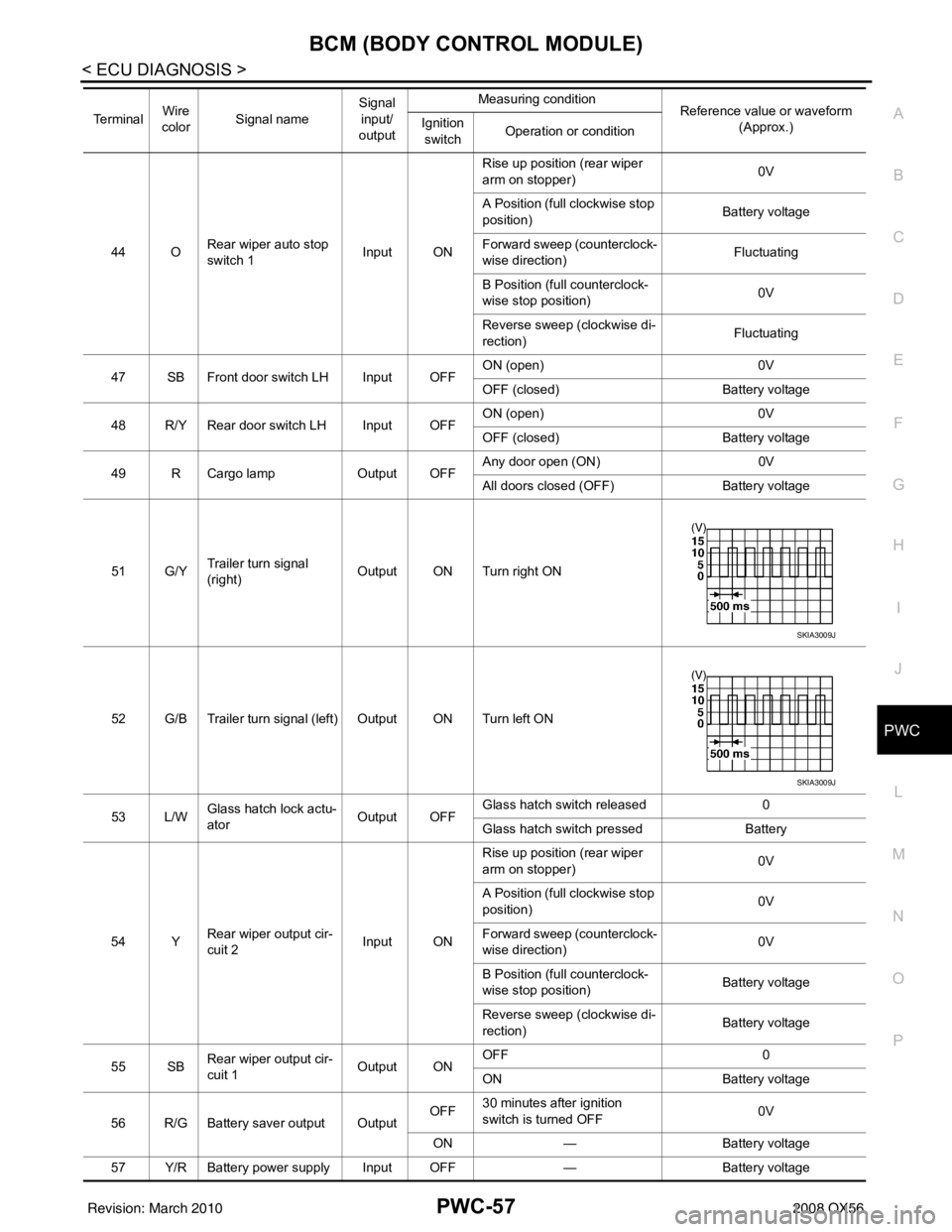
51 G/Y Trailer turn signal
(right) Output ON Turn right ON
52 G/B Trailer turn signal (left) Output ON Turn left ON
53 L/W Glass hatch lock actu-
ator
Output OFFGlass hatch switch released
0
Glass hatch switch pressed Battery
54 Y Rear wiper output cir-
cuit 2 Input ONRise up position (rear wiper
arm on stopper)
0V
A Position (full clockwise stop
position) 0V
Forward sweep (counterclock-
wise direction) 0V
B Position (full counterclock-
wise stop position) Battery voltage
Reverse sweep (clockwise di-
rection) Battery voltage
55 SB Rear wiper output cir-
cuit 1 Output ONOFF
0
ON Battery voltage
56 R/G Battery saver output Output OFF
30 minutes after ignition
switch is turned OFF 0V
ON — Battery voltage
57 Y/R Battery power supply Input OFF —Battery voltage
Te r m i n a l
Wire
color Signal name Signal
input/
output Measuring condition
Reference value or waveform
(Approx.)
Ignition
switch Operation or condition
SKIA3009J
SKIA3009J
Revision: March 2010
2008 QX56
Page 3004 of 4083
RF-20
< ECU DIAGNOSIS >
BCM (BODY CONTROL MODULE)
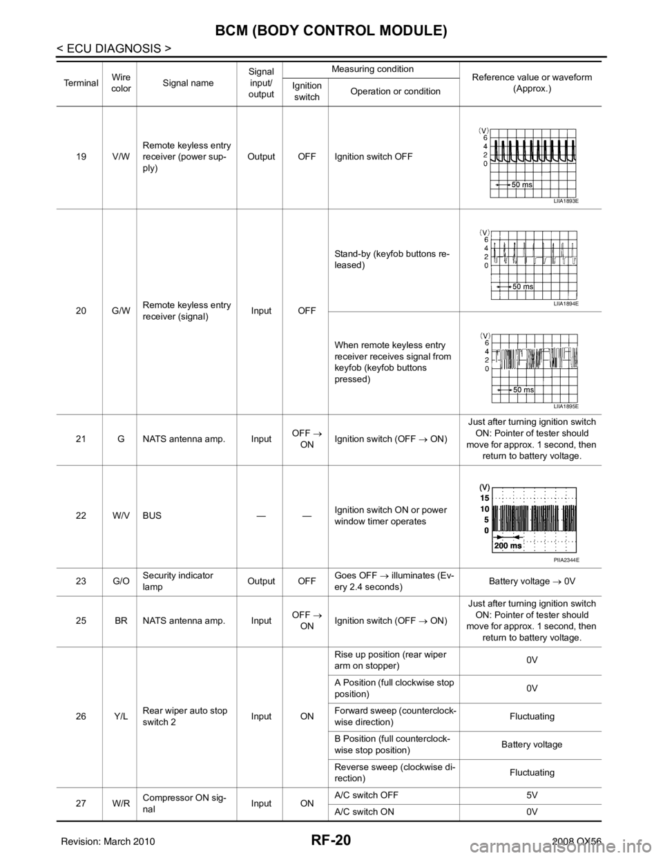
19 V/WRemote keyless entry
receiver (power sup-
ply) Output OFF Ignition switch OFF
20 G/W Remote keyless entry
receiver (signal) Input OFFStand-by (keyfob buttons re-
leased)
When remote keyless entry
receiver receives signal from
keyfob (keyfob buttons
pressed)
21 G NATS antenna amp. Input OFF
→
ON Ignition switch (OFF
→ ON)Just after turning ignition switch
ON: Pointer of tester should
move for approx. 1 second, then return to battery voltage.
22 W/V BUS — —Ignition switch ON or power
window timer operates
23 G/O Security indicator
lamp Output OFF
Goes OFF
→ illuminates (Ev-
ery 2.4 seconds) Battery voltage
→ 0V
25 BR NATS antenna amp. Input OFF
→
ON Ignition switch (OFF
→ ON)Just after turning ignition switch
ON: Pointer of tester should
move for approx. 1 second, then return to battery voltage.
26 Y/L Rear wiper auto stop
switch 2 Input ONRise up position (rear wiper
arm on stopper)
0V
A Position (full clockwise stop
position) 0V
Forward sweep (counterclock-
wise direction) Fluctuating
B Position (full counterclock-
wise stop position) Battery voltage
Reverse sweep (clockwise di-
rection) Fluctuating
27 W/R Compressor ON sig-
nal Input ONA/C switch OFF
5V
A/C switch ON 0V
Te r m i n a l
Wire
color Signal name Signal
input/
output Measuring condition
Reference value or waveform
(Approx.)
Ignition
switch Operation or condition
LIIA1893E
LIIA1894E
LIIA1895E
PIIA2344E
Revision: March 2010
2008 QX56
Page 3006 of 4083
RF-22
< ECU DIAGNOSIS >
BCM (BODY CONTROL MODULE)
44 ORear wiper auto stop
switch 1 Input ONRise up position (rear wiper
arm on stopper)
0V
A Position (full clockwise stop
position) Battery voltage
Forward sweep (counterclock-
wise direction) Fluctuating
B Position (full counterclock-
wise stop position) 0V
Reverse sweep (clockwise di-
rection) Fluctuating
47 SB Front door switch LH Input OFF ON (open)
0V
OFF (closed) Battery voltage
48 R/Y Rear door switch LH Input OFF ON (open)
0V
OFF (closed) Battery voltage
49 R Cargo lamp Output OFFAny door open (ON)
0V
All doors closed (OFF) Battery voltage
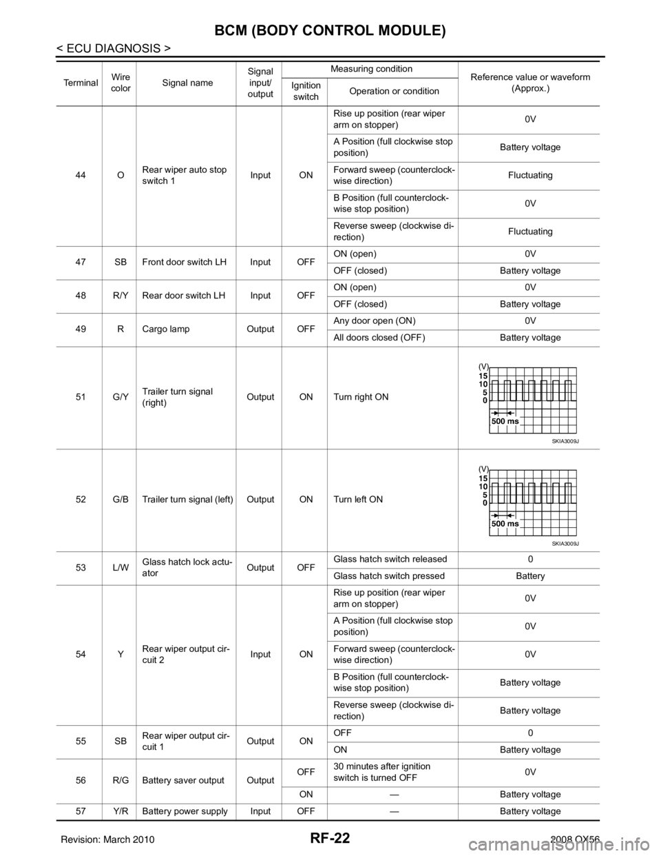
51 G/Y Trailer turn signal
(right) Output ON Turn right ON
52 G/B Trailer turn signal (l eft) Output ON Turn left ON
53 L/W Glass hatch lock actu-
ator
Output OFFGlass hatch switch released
0
Glass hatch switch pressed Battery
54 Y Rear wiper output cir-
cuit 2 Input ONRise up position (rear wiper
arm on stopper)
0V
A Position (full clockwise stop
position) 0V
Forward sweep (counterclock-
wise direction) 0V
B Position (full counterclock-
wise stop position) Battery voltage
Reverse sweep (clockwise di-
rection) Battery voltage
55 SB Rear wiper output cir-
cuit 1 Output ONOFF
0
ON Battery voltage
56 R/G Battery saver output Output OFF
30 minutes after ignition
switch is turned OFF 0V
ON — Battery voltage
57 Y/R Battery power supply Input OFF —Battery voltage
Te r m i n a l
Wire
color Signal name Signal
input/
output Measuring condition
Reference value or waveform
(Approx.)
Ignition
switch Operation or condition
SKIA3009J
SKIA3009J
Revision: March 2010
2008 QX56
Page 3024 of 4083
RF-40
< SYMPTOM DIAGNOSIS >
SQUEAK AND RATTLE TROUBLE DIAGNOSES
SQUEAK AND RATTLE TROUBLE DIAGNOSES
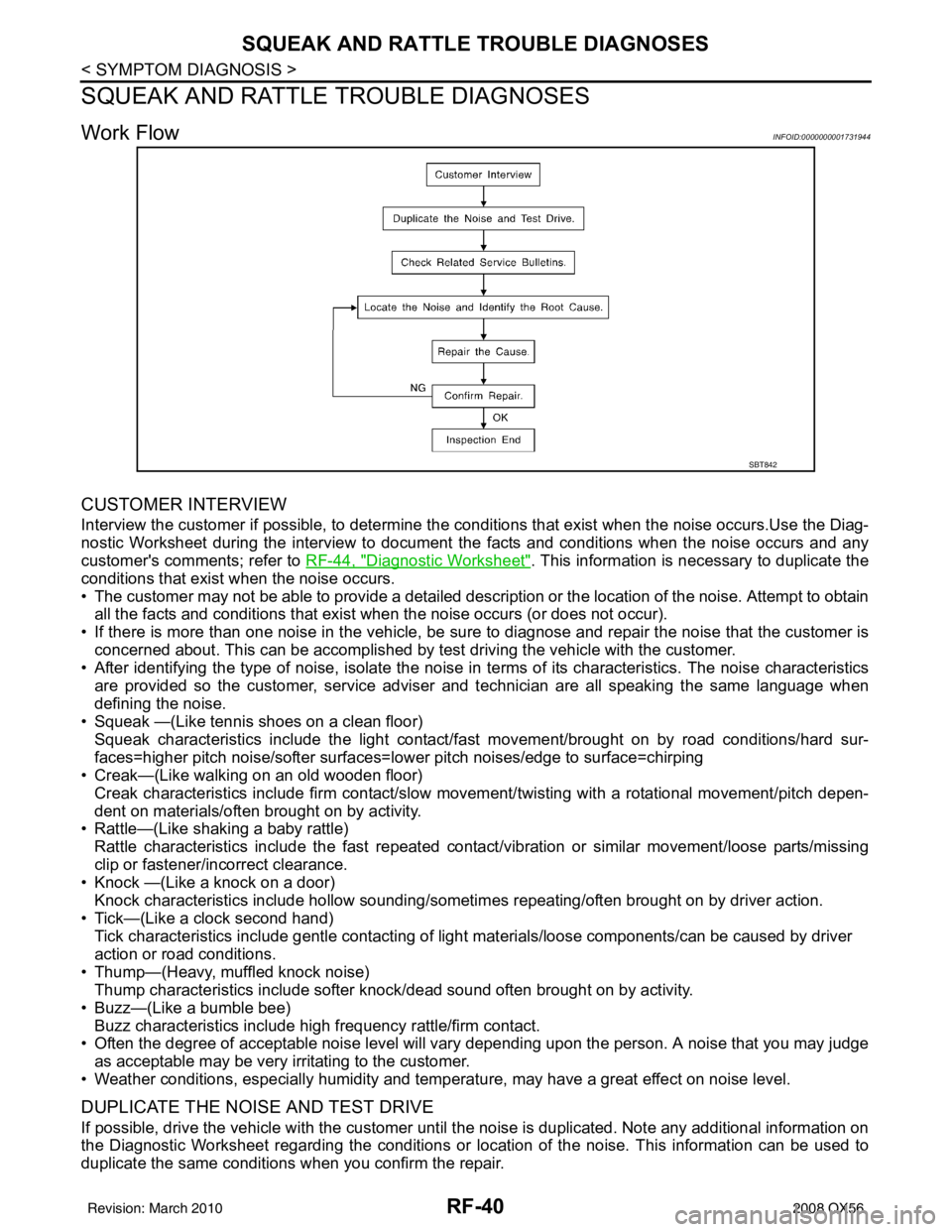
Work FlowINFOID:0000000001731944
CUSTOMER INTERVIEW
Interview the customer if possible, to determine the conditions that exist when the noise occurs.Use the Diag-
nostic Worksheet during the interview to document the facts and conditions when the noise occurs and any
customer's comments; refer to RF-44, "
Diagnostic Worksheet". This information is necessary to duplicate the
conditions that exist when the noise occurs.
• The customer may not be able to provide a detailed description or the location of the noise. Attempt to obtain all the facts and conditions that exist w hen the noise occurs (or does not occur).
• If there is more than one noise in the vehicle, be sure to diagnose and repair the noise that the customer is
concerned about. This can be accomplished by test driving the vehicle with the customer.
• After identifying the type of noise, isolate the noise in terms of its characteristics. The noise characteristics
are provided so the customer, service adviser and technician are all speaking the same language when
defining the noise.
• Squeak —(Like tennis shoes on a clean floor)
Squeak characteristics include the light contact/fa st movement/brought on by road conditions/hard sur-
faces=higher pitch noise/softer surfaces=l ower pitch noises/edge to surface=chirping
• Creak—(Like walking on an old wooden floor)
Creak characteristics include firm contact/slow mo vement/twisting with a rotational movement/pitch depen-
dent on materials/often brought on by activity.
• Rattle—(Like shaking a baby rattle)
Rattle characteristics include the fast repeated contac t/vibration or similar movement/loose parts/missing
clip or fastener/incorrect clearance.
• Knock —(Like a knock on a door)
Knock characteristics include hollow sounding/someti mes repeating/often brought on by driver action.
• Tick—(Like a clock second hand) Tick characteristics include gentle contacting of light materials/loose components/can be caused by driver
action or road conditions.
• Thump—(Heavy, muffled knock noise) Thump characteristics include softer k nock/dead sound often brought on by activity.
• Buzz—(Like a bumble bee)
Buzz characteristics include hi gh frequency rattle/firm contact.
• Often the degree of acceptable noise level will vary depending upon the person. A noise that you may judge as acceptable may be very irritating to the customer.
• Weather conditions, especially humidity and temperat ure, may have a great effect on noise level.
DUPLICATE THE NOISE AND TEST DRIVE
If possible, drive the vehicle with the customer until the noise is duplicated. Note any additional information on
the Diagnostic Worksheet regarding the conditions or lo cation of the noise. This information can be used to
duplicate the same conditions when you confirm the repair.
SBT842
Revision: March 2010 2008 QX56