Page 2041 of 4083

HEADLAMPEXL-113
< REMOVAL AND INSTALLATION >
C
DE
F
G H
I
J
K
M A
B
EXL
N
O P
REMOVAL AND INSTALLATION
HEADLAMP
Bulb ReplacementINFOID:0000000001551508
CAUTION:
• Disconnect battery negative terminal before touc hing xenon bulb or headlamp wiring harness
assembly.
• Turn headlamp switch OFF before di sconnecting headlamp harness connector.
• Do not touch bulb by hand right after being turned off. Burning may result.
• Do not touch the glass of bulb directly by hand. Keep grease and other oily substances away from it.
• Do not turn xenon bulb ON when xenon bulb is removed fr om front combination lamp assembly.
• After installing the bu lb, be sure to install the bulb socket securely to ensure watertightness.
• Do not leave bulb out of front combination lamp assembly for a lo ng time because dust, moisture,
smoke, etc. may affect the performance of the lamp. When replacing bulb, be sure to replace it with a
new one.
HEADLAMP (OUTER SIDE), FOR LOW BEAM
Removal
1. Position fender protector aside.
2. Turn headlamp switch OFF.
3. Disconnect battery negative terminal.
4. Remove ballast.
5. Disconnect headlamp electrical connector.
6. Release bulb retaining spring and pull bulb straight out.
Installation
Installation is in the reverse order of removal.
HEADLAMP (INNER SIDE), FOR HIGH BEAM
Removal
1. Turn headlamp switch OFF.
2. Disconnect headlamp electrical connector.
3. Turn the bulb counterclockwise to remove it.
Installation
Installation is in the reverse order of removal.
FRONT PARKING LAMP (INNER OR OUTER)
Removal
1. Turn the bulb socket counterclockwise to unlock it.
2. Pull the bulb to remove it from the socket.
Installation
Installation is in the reverse order of removal.
SIDE MARKER LAMP (FRONT)
Removal
1. Position fender protector aside.
2. Turn the side marker lamp (front) bulb socket count erclockwise and remove side marker lamp (front) bulb
socket.
3. Pull to remove side marker lamp (front) from the side marker lamp (front) bulb socket.
Installation
Installation is in the reverse order of removal.
Revision: March 2010 2008 QX56
Page 2043 of 4083
HEADLAMPEXL-115
< REMOVAL AND INSTALLATION >
C
DE
F
G H
I
J
K
M A
B
EXL
N
O P
Disassembly
1. Remove ballast.
2. Release xenon bulb retaining spring and remove xenon bulb.
3. Turn high beam bulb counterclockwise to unlock and remove high beam bulb.
4. Turn parking lamp bulb (inner) socket counterclockwise to unlock and remove parking lamp bulb.
5. Turn parking lamp bulb (outer) socket counterclockwise to unlock and remove parking lamp bulb.
6. Turn side marker lamp (front) bulb socket counterclo
ckwise to unlock and remove side marker lamp (front)
bulb.
Assembly
Assembly is in the reverse order of disassembly.
4. Xenon bulb (low beam) 5. Side marker lamp (front) bulb 6. Ballast
7. Wiring harness assembly
Revision: March 2010 2008 QX56
Page 2044 of 4083
EXL-116
< REMOVAL AND INSTALLATION >
AUTO LIGHT SYSTEM
AUTO LIGHT SYSTEM
Removal and InstallationINFOID:0000000001547169
OPTICAL SENSOR
Removal
1. Remove defroster grille. Refer to IP-11, "Exploded View".
2. Disconnect the optical sensor connector.
3. Turn the optical sensor counterclockwise to remove it from defroster grille.
Installation
Installation is in the reverse order of removal.
WKIA1061E
Revision: March 2010 2008 QX56
Page 2045 of 4083

FRONT FOG LAMPEXL-117
< REMOVAL AND INSTALLATION >
C
DE
F
G H
I
J
K
M A
B
EXL
N
O P
FRONT FOG LAMP
Bulb ReplacementINFOID:0000000001553094
FRONT FOG LAMP
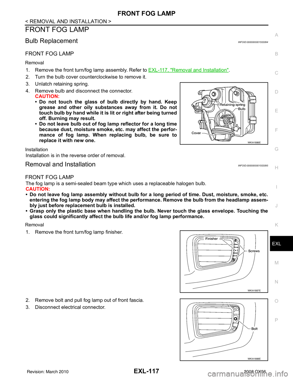
Removal
1. Remove the front turn/fog lamp assembly. Refer to EXL-117, "Removal and Installation".
2. Turn the bulb cover counterclockwise to remove it.
3. Unlatch retaining spring.
4. Remove bulb and disconnect the connector. CAUTION:
• Do not touch the glass of bulb directly by hand. Keep
grease and other oily substances away from it. Do not
touch bulb by hand while it is lit or right after being turned
off. Burning may result.
• Do not leave bulb out of fog lamp reflector for a long time
because dust, moisture smoke, etc. may affect the perfor-
mance of fog lamp. When replacing bulb, be sure to
replace it with new one.
Installation
Installation is in the reverse order of removal.
Removal and InstallationINFOID:0000000001553095
FRONT FOG LAMP
The fog lamp is a semi-sealed beam type which uses a replaceable halogen bulb.
CAUTION:
• Do not leave fog lamp assembly without bulb for a l ong period of time. Dust, moisture, smoke, etc.
entering the fog lamp body may affect the performance. Remove the bulb from the headlamp assem-
bly just before replacement bulb is installed.
• Grasp only the plastic base when handling the bulb. Never touch the glass envelope. Touching the
glass could significantly a ffect the bulb life and/or fog lamp performance.
Removal
1. Remove the front turn/fog lamp finisher.
2. Remove bolt and pull fog lamp out of front fascia.
3. Disconnect electrical connector.
WKIA1886E
WKIA1887E
WKIA1888E
Revision: March 2010 2008 QX56
Page 2050 of 4083
EXL-122
< REMOVAL AND INSTALLATION >
LICENSE PLATE LAMP
LICENSE PLATE LAMP
Bulb ReplacementINFOID:0000000001679761
LICENSE PLATE LAMP
Removal
1. Remove back door lower finisher. Refer to EXT-24, "Removal and Installation".
2. Turn bulb socket counterclockwise to remove it.
3. Pull bulb from socket.
Installation
Installation is in the reverse order of removal.
Removal and InstallationINFOID:0000000001679762
LICENSE PLATE LAMP
Removal
1. Remove back door lower finisher. Refer to INT-21, "Removal and Installation".
2. Remove license plate lamp screws.
3. Remove license plate lamp.
Installation
Installation is in the reverse order of removal.
Revision: March 2010 2008 QX56
Page 2052 of 4083
EXL-124
< REMOVAL AND INSTALLATION >
REAR COMBINATION LAMP
REAR COMBINATION LAMP
Bulb ReplacementINFOID:0000000001547176
REMOVAL
1. Remove rear combination lamp bolts.
2. Pull rear combination lamp to remove.
3. Turn bulb socket counterclockwise and unlock it.
4. Remove bulb.
INSTALLATION
Installation is in the reverse order of removal.
Removal and InstallationINFOID:0000000001547177
REMOVAL
1. Remove rear combination lamp bolts.
2. Pull rear combination lamp to remove.
3. Disconnect rear combination lamp connector.
INSTALLATION
Installation is in the reverse order of removal.
WKIA1393E
WKIA1393E
Revision: March 20102008 QX56
Page 2058 of 4083

SQUEAK AND RATTLE TROUBLE DIAGNOSESEXT-5
< SERVICE INFORMATION >
C
DE
F
G H
I
J
L
M A
B
EXT
N
O P
SQUEAK AND RATTLE TROUBLE DIAGNOSES
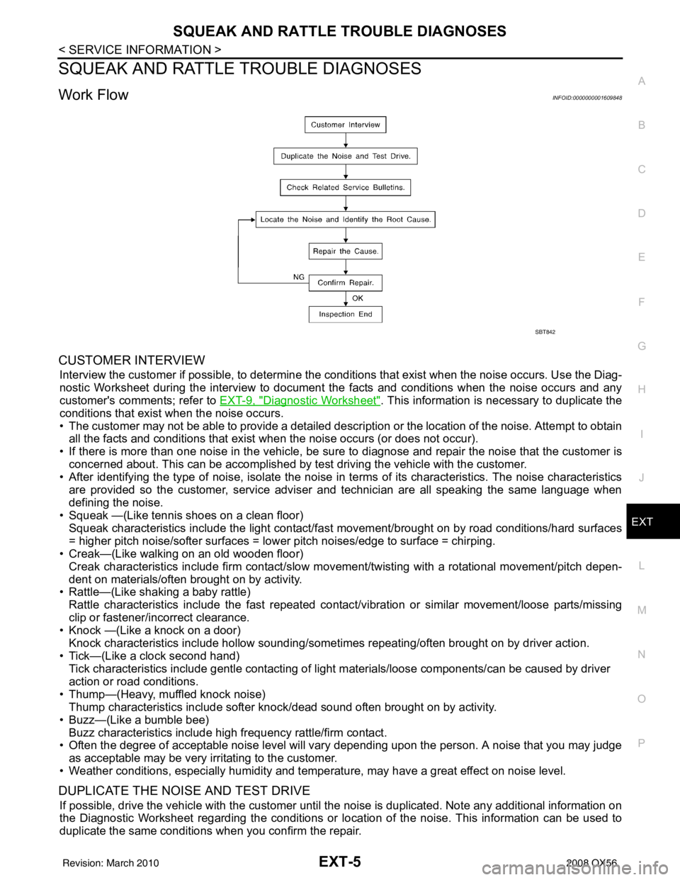
Work FlowINFOID:0000000001609848
CUSTOMER INTERVIEW
Interview the customer if possible, to determine the conditions that exist when the noise occurs. Use the Diag-
nostic Worksheet during the interv iew to document the facts and conditions when the noise occurs and any
customer's comments; refer to EXT-9, "
Diagnostic Worksheet". This information is necessary to duplicate the
conditions that exist when the noise occurs.
• The customer may not be able to provide a detailed descr iption or the location of the noise. Attempt to obtain
all the facts and conditions that exist when the noise occurs (or does not occur).
• If there is more than one noise in the vehicle, be sure to diagnose and repair the noise that the customer is
concerned about. This can be accomplished by test driving the vehicle with the customer.
• After identifying the type of noise, isolate the noise in terms of its characteristics. The noise characteristics
are provided so the customer, service adviser and technician are all speaking the same language when
defining the noise.
• Squeak —(Like tennis shoes on a clean floor)
Squeak characteristics include the light contact/fast movement/brought on by road conditions/hard surfaces
= higher pitch noise/softer surfaces = lower pitch noises/edge to surface = chirping.
• Creak—(Like walking on an old wooden floor)
Creak characteristics include firm contact/slow mo vement/twisting with a rotational movement/pitch depen-
dent on materials/often brought on by activity.
• Rattle—(Like shaking a baby rattle)
Rattle characteristics include the fast repeated contac t/vibration or similar movement/loose parts/missing
clip or fastener/incorrect clearance.
• Knock —(Like a knock on a door)
Knock characteristics include hollow sounding/someti mes repeating/often brought on by driver action.
• Tick—(Like a clock second hand) Tick characteristics include gentle contacting of li ght materials/loose components/can be caused by driver
action or road conditions.
• Thump—(Heavy, muffled knock noise) Thump characteristics include softer k nock/dead sound often brought on by activity.
• Buzz—(Like a bumble bee)
Buzz characteristics include high frequency rattle/firm contact.
• Often the degree of acceptable noise level will vary depending upon the person. A noise that you may judge as acceptable may be very irritating to the customer.
• Weather conditions, especially humidity and temperature, may have a great effect on noise level.
DUPLICATE THE NOISE AND TEST DRIVE
If possible, drive the vehicle with the customer until the noise is duplicated. Note any additional information on
the Diagnostic Worksheet regarding the conditions or lo cation of the noise. This information can be used to
duplicate the same conditions when you confirm the repair.
SBT842
Revision: March 2010 2008 QX56
Page 2108 of 4083

FL-8
< REMOVAL AND INSTALLATION >
FUEL LEVEL SENSOR UNIT, FUEL FILTER AND FUEL PUMP ASSEMBLY
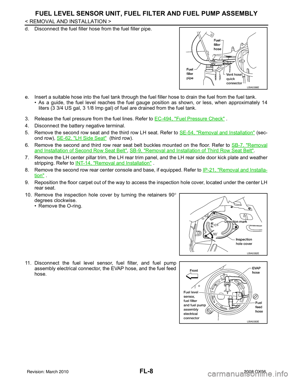
d. Disconnect the fuel filler hose from the fuel filler pipe.
e. Insert a suitable hose into the fuel tank through the fuel filler hose to drain the fuel from the fuel tank.
• As a guide, the fuel level reaches the fuel gauge position as shown, or less, when approximately 14
liters (3 3/4 US gal, 3 1/8 Imp gal) of fuel are drained from the fuel tank.
3. Release the fuel pressure from the fuel lines. Refer to EC-494, "
Fuel Pressure Check" .
4. Disconnect the battery negative terminal.
5. Remove the second row seat and the third row LH seat. Refer to SE-54, "
Removal and Installation" (sec-
ond row), SE-62, "
LH Side Seat" (third row).
6. Remove the second and third row rear seat belt buckles mounted on the floor. Refer to SB-7, "
Removal
and Installation of Second Row Seat Belt", SB-9, "Removal and Installation of Third Row Seat Belt".
7. Remove the LH center pillar trim, the LH rear trim panel, and the LH rear side door kick plate and weather
stripping. Refer to INT-14, "
Removal and Installation" .
8. Remove the second row rear center console and base, if equipped. Refer to IP-21, "
Removal and Installa-
tion" .
9. Reposition the floor carpet out of the way to access the inspection hole cover, located under the center LH
rear seat.
10. Remove the inspection hole cover by turning the retainers 90 °
degrees clockwise.
• Remove the O-ring.
11. Disconnect the fuel level sensor, fuel filter, and fuel pump assembly electrical connector, the EVAP hose, and the fuel feed
hose.
LBIA0386E
LBIA0382E
LBIA0383E
Revision: March 2010 2008 QX56