2008 INFINITI QX56 turn signal
[x] Cancel search: turn signalPage 3694 of 4083
SYSTEM SYMPTOMTM-147
< SYMPTOM DIAGNOSIS >
CEF
G H
I
J
K L
M A
B
TM
N
O P
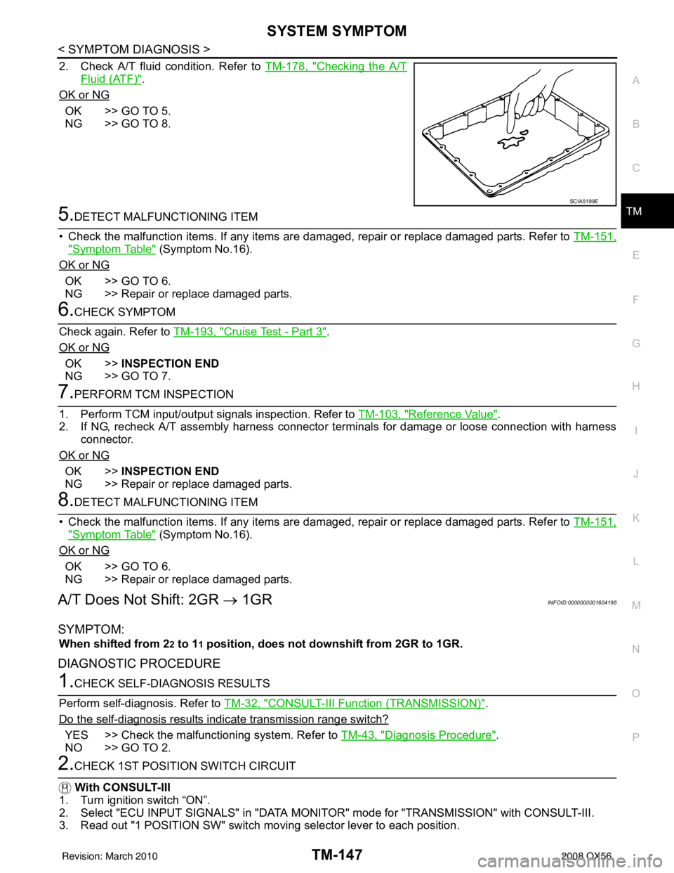
2. Check A/T fluid condition. Refer to TM-178, "Checking the A/T
Fluid (ATF)".
OK or NG
OK >> GO TO 5.
NG >> GO TO 8.
5.DETECT MALFUNCTIONING ITEM
• Check the malfunction items. If any items are damaged, repair or replace damaged parts. Refer to TM-151,
"Symptom Table" (Symptom No.16).
OK or NG
OK >> GO TO 6.
NG >> Repair or replace damaged parts.
6.CHECK SYMPTOM
Check again. Refer to TM-193, "
Cruise Test - Part 3".
OK or NG
OK >> INSPECTION END
NG >> GO TO 7.
7.PERFORM TCM INSPECTION
1. Perform TCM input/output signals inspection. Refer to TM-103, "
Reference Value".
2. If NG, recheck A/T assembly harness connector terminals for damage or loose connection with harness connector.
OK or NG
OK >> INSPECTION END
NG >> Repair or replace damaged parts.
8.DETECT MALFUNCTIONING ITEM
• Check the malfunction items. If any items are damaged, repair or replace damaged parts. Refer to TM-151,
"Symptom Table" (Symptom No.16).
OK or NG
OK >> GO TO 6.
NG >> Repair or replace damaged parts.
A/T Does Not Shift: 2GR → 1GRINFOID:0000000001604198
SYMPTOM:
When shifted from 22 to 11 position, does not downshift from 2GR to 1GR.
DIAGNOSTIC PROCEDURE
1.CHECK SELF-DIAGNOSIS RESULTS
Perform self-diagnosis. Refer to TM-32, "
CONSULT-III Function (TRANSMISSION)".
Do the self-diagnosis results i ndicate transmission range switch?
YES >> Check the malfunctioning system. Refer to TM-43, "Diagnosis Procedure".
NO >> GO TO 2.
2.CHECK 1ST POSITION SWITCH CIRCUIT
With CONSULT-III
1. Turn ignition switch “ON”.
2. Select "ECU INPUT SIGNALS" in "DATA MONITO R" mode for "TRANSMISSION" with CONSULT-III.
3. Read out "1 POSITION SW" switch mo ving selector lever to each position.
SCIA5199E
Revision: March 2010 2008 QX56
Page 3696 of 4083
SYSTEM SYMPTOMTM-149
< SYMPTOM DIAGNOSIS >
CEF
G H
I
J
K L
M A
B
TM
N
O P
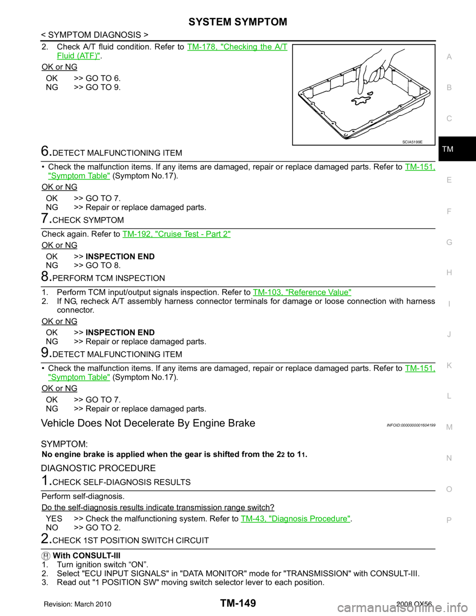
2. Check A/T fluid condition. Refer to TM-178, "Checking the A/T
Fluid (ATF)".
OK or NG
OK >> GO TO 6.
NG >> GO TO 9.
6.DETECT MALFUNCTIONING ITEM
• Check the malfunction items. If any items are damaged, repair or replace damaged parts. Refer to TM-151,
"Symptom Table" (Symptom No.17).
OK or NG
OK >> GO TO 7.
NG >> Repair or replace damaged parts.
7.CHECK SYMPTOM
Check again. Refer to TM-192, "
Cruise Test - Part 2"
OK or NG
OK >>INSPECTION END
NG >> GO TO 8.
8.PERFORM TCM INSPECTION
1. Perform TCM input/output signals inspection. Refer to TM-103, "
Reference Value"
2. If NG, recheck A/T assembly harness connector terminals for damage or loose connection with harness
connector.
OK or NG
OK >> INSPECTION END
NG >> Repair or replace damaged parts.
9.DETECT MALFUNCTIONING ITEM
• Check the malfunction items. If any items are damaged, repair or replace damaged parts. Refer to TM-151,
"Symptom Table" (Symptom No.17).
OK or NG
OK >> GO TO 7.
NG >> Repair or replace damaged parts.
Vehicle Does Not Decelerate By Engine BrakeINFOID:0000000001604199
SYMPTOM:
No engine brake is applied when the gear is shifted from the 22 to 11.
DIAGNOSTIC PROCEDURE
1.CHECK SELF-DIAGNOSIS RESULTS
Perform self-diagnosis.
Do the self-diagnosis results i ndicate transmission range switch?
YES >> Check the malfunctioning system. Refer to TM-43, "Diagnosis Procedure".
NO >> GO TO 2.
2.CHECK 1ST POSITION SWITCH CIRCUIT
With CONSULT-III
1. Turn ignition switch “ON”.
2. Select "ECU INPUT SIGNALS" in "DATA MONITO R" mode for "TRANSMISSION" with CONSULT-III.
3. Read out "1 POSITION SW" moving switch selector lever to each position.
SCIA5199E
Revision: March 2010 2008 QX56
Page 3719 of 4083
TM-172
< SYMPTOM DIAGNOSIS >
SYSTEM SYMPTOM
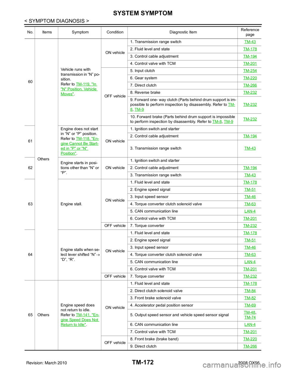
60Others Vehicle runs with
transmission in “N” po-
sition.
Refer to TM-119, "In
"N" Position, Vehicle
Moves".
ON vehicle
1. Transmission range switch
TM-43
2. Fluid level and stateTM-178
3. Control cable adjustmentTM-194
4. Control valve with TCMTM-201
OFF vehicle5. Input clutch
TM-254
6. Gear systemTM-220
7. Direct clutchTM-266
8. Reverse brakeTM-232
9. Forward one- way clutch (Parts behind drum support is im-
possible to perform inspection by disassembly. Refer to TM-
8, TM-9
TM-232
10. Forward brake (Parts behind drum support is impossible
to perform inspection by disassembly. Refer to TM-8
, TM-9TM-232
61 Engine does not start
in “N” or “P” position.
Refer to TM-118, "En-
gine Cannot Be Start-
ed in "P" or "N"
Position".ON vehicle1. Ignition switch and starter
2. Control cable adjustment
TM-194
3. Transmission range switch TM-43
62Engine starts in posi-
tions other than “N” or
“P”.
ON vehicle1. Ignition switch and starter
2. Control cable adjustment
TM-194
3. Transmission range switch TM-43
63Engine stall. ON vehicle1. Fluid level and state
TM-178
2. Engine speed signal TM-51
3. Input speed sensorTM-46
4. Torque converter clutch solenoid valveTM-63
5. CAN communication line LAN-4
6. Control valve with TCMTM-201
OFF vehicle 7. Torque converter TM-232
64Engine stalls when se-
lect lever shifted “N”
→
“D”, “R”. ON vehicle1. Fluid level and state
TM-178
2. Engine speed signal TM-51
3. Input speed sensorTM-46
4. Torque converter clutch solenoid valveTM-63
5. CAN communication line LAN-4
6. Control valve with TCMTM-201
OFF vehicle 7. Torque converter TM-232
65 OthersEngine speed does
not return to idle.
Refer to TM-141, "En-
gine Speed Does Not
Return to Idle".ON vehicle 1. Fluid level and state
TM-178
2. Direct clutch solenoid valve TM-84
3. Front brake solenoid valveTM-82
4. Accelerator pedal position sensorTM-69
5. Output speed sensor and vehicle speed sensor signalTM-48,
TM-74
6. CAN communication line LAN-4
7. Control valve with TCMTM-201
OFF vehicle8. Front brake (brake band)
TM-2209. Direct clutchTM-266
No. ItemsSymptom Condition Diagnostic ItemReference
page
Revision: March 2010 2008 QX56
Page 3739 of 4083
TM-192
< ON-VEHICLE MAINTENANCE >
ROAD TEST
NO >> Enter a check mark at “A/T Does Not Hold Lock-up Condition” on the diagnostics worksheet, thencontinue the road test.
8.CHECK LOCK-UP RELEASE
Check lock-up cancellation by depressing brake pedal lightly to decelerate. With CONSULT-III
Select “TCC SOLENOID 0.00A” with the “MAIN SIGNAL” mode for A/T.
Does lock-up cancel?
YES >> GO TO 9.
NO >> Enter a check mark at “Lock-up Is Not Released” on the diagnostics worksheet, then continue the road test.
9.CHECK SHIFT-DOWN D5 → D4
Decelerate by pressing lightly on the brake pedal. With CONSULT-III
Read the gear position and engine speed.
When the A/T shift-down D5
→ D4, does the engine speed drop smoothly back to idle?
YES >> 1. Stop the vehicle. 2. Go to Cruise test - Part 2 (Refer to AT 58).
NO >> Enter a check mark at “Engine Speed Does Not Return to Idle” on the diagnostics worksheet, then continue the road test. Go to Cruise test - Part 2 (Refer to AT 58).
Cruise Test - Part 2INFOID:0000000001696162
1.CHECK STARTING FROM D1
1. Move selector lever the “D” position.
2. Accelerate at half throttle. With CONSULT-III
Read the gear position.
Does it start from D1?
YES >> GO TO 2.
NO >> Enter a check mark at “Vehicle Cannot Be Started From D1” on the diagnostics worksheet, then continue the road test.
2.CHECK SHIFT-UP D1 → D2
Press the accelerator pedal down all the way and ins pect whether or not the transmission shifts up (D1 → D2)
at the correct speed.
• Refer to TM-291, "
Vehicle Speed at Which Gear Shifting Occurs".
With CONSULT-III
Read the gear position, throttle position and vehicle speed.
Does the A/T shift-up D1
→ D2 at the correct speed?
YES >> GO TO 3.
NO >> Enter a check mark at “Vehicle Does Not Shift: D1 → D2” on the diagnostics worksheet, then con-
tinue the road test.
3.CHECK SHIFT-UP D2 → D3
Press the accelerator pedal down all the way and ins pect whether or not the transmission shifts up (D2 → D3)
at the correct speed.
• Refer to TM-291, "
Vehicle Speed at Which Gear Shifting Occurs".
With CONSULT-III
Read the gear position, throttle position and vehicle speed.
Does the A/T shift-up D2
→ D3 at the correct speed?
YES >> GO TO 4.
NO >> Enter a check mark at “Vehicle Does Not Shift: D2 → D3” on the diagnostics worksheet, then con-
tinue the road test.
4.CHECK SHIFT-UP D3 → D4 AND ENGINE BRAKE
Revision: March 2010 2008 QX56
Page 3885 of 4083
WCS-8
< FUNCTION DIAGNOSIS >
WARNING CHIME SYSTEM
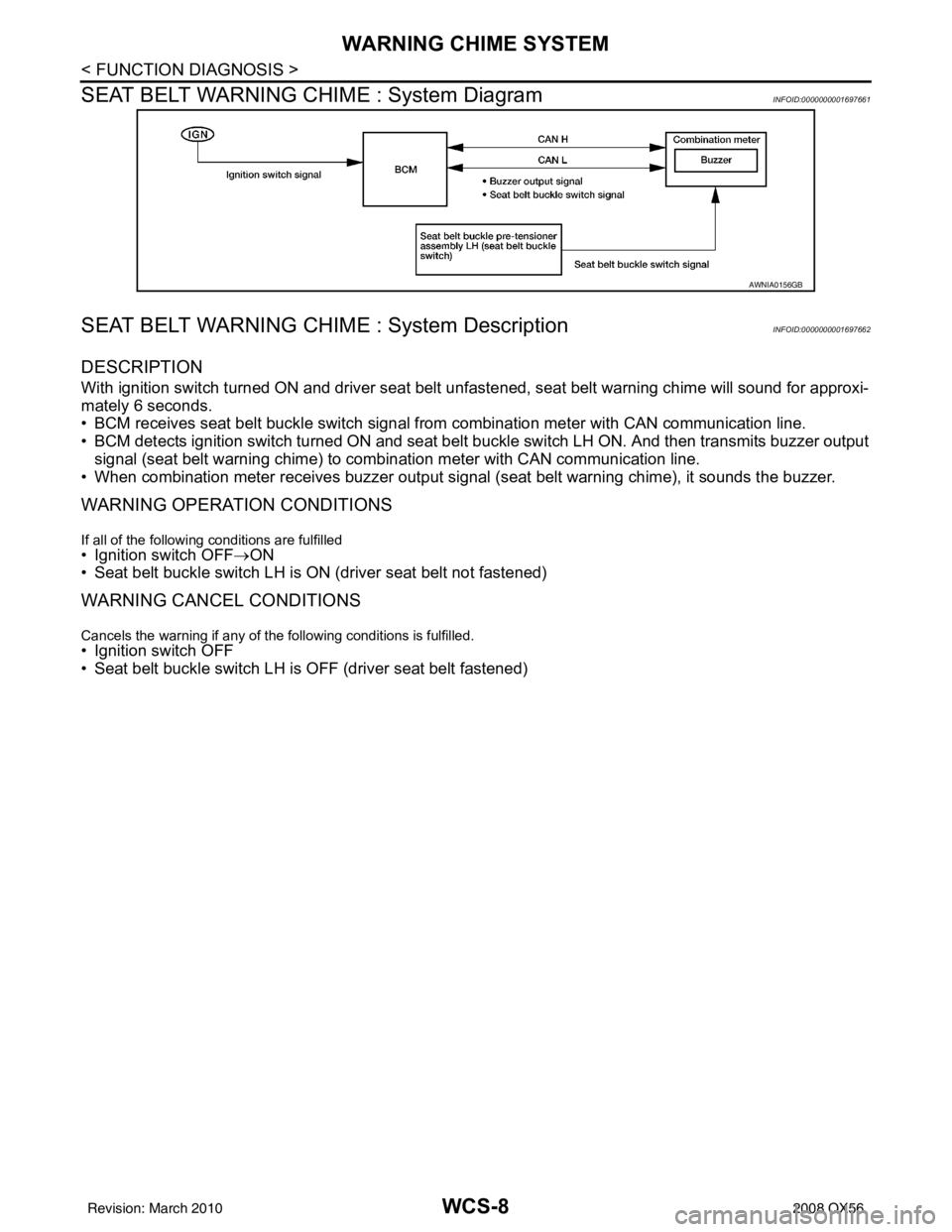
SEAT BELT WARNING CHIME : System Diagram
INFOID:0000000001697661
SEAT BELT WARNING CHIME : System DescriptionINFOID:0000000001697662
DESCRIPTION
With ignition switch turned ON and driver seat belt unfastened, seat belt warning chime will sound for approxi-
mately 6 seconds.
• BCM receives seat belt buckle switch signal from combination meter with CAN communication line.
• BCM detects ignition switch turned ON and seat belt buckle switch LH ON. And then transmits buzzer output signal (seat belt warning chime) to combination meter with CAN communication line.
• When combination meter receives buzzer output signal (seat belt warning chime), it sounds the buzzer.
WARNING OPERATION CONDITIONS
If all of the following conditions are fulfilled• Ignition switch OFF→ON
• Seat belt buckle switch LH is ON (driver seat belt not fastened)
WARNING CANCEL CONDITIONS
Cancels the warning if any of the following conditions is fulfilled.
• Ignition switch OFF
• Seat belt buckle switch LH is OFF (driver seat belt fastened)
AWNIA0156GB
Revision: March 2010 2008 QX56
Page 3891 of 4083
![INFINITI QX56 2008 Factory Service Manual WCS-14
< FUNCTION DIAGNOSIS >
DIAGNOSIS SYSTEM (METER)
X: Applicable
Display item [Unit]MAIN
SIGNALS SELECTION
FROM MENU Description
SPEED METER [km/h] or [mph] X X Displays the value of vehicle spee INFINITI QX56 2008 Factory Service Manual WCS-14
< FUNCTION DIAGNOSIS >
DIAGNOSIS SYSTEM (METER)
X: Applicable
Display item [Unit]MAIN
SIGNALS SELECTION
FROM MENU Description
SPEED METER [km/h] or [mph] X X Displays the value of vehicle spee](/manual-img/42/57030/w960_57030-3890.png)
WCS-14
< FUNCTION DIAGNOSIS >
DIAGNOSIS SYSTEM (METER)
X: Applicable
Display item [Unit]MAIN
SIGNALS SELECTION
FROM MENU Description
SPEED METER [km/h] or [mph] X X Displays the value of vehicle speed signal.
SPEED OUTPUT [km/h] or [mph] X XDisplays the value of vehicle speed signal, which is transmitted to
each unit with
CAN communication.
TACHO METER [rpm] XX Displays the value of engine speed signal, which is input from ECM.
FUEL METER [lit.] XXDisplays the value, which processes a resistance signal from fuel
gauge.
W TEMP METER [ °C] or [° F] X XDisplays the value of engine coolant temperature signal, which is in-
put from ECM.
ABS W/L [ON/OFF] X Displays [ON/OFF] condition of ABS warning lamp.
VDC/TCS IND [ON/OFF] X Displays [ON/OFF] condition of VDC OFF indicator lamp.
SLIP IND [ON/OFF] X Displays [ON/OFF] condition of SLIP indicator lamp.
BRAKE W/L [ON/OFF] X Displays [ON/OFF] condition of brake warning lamp.*
DOOR W/L [ON/OFF] X Displays [ON/OFF] condition of door warning lamp.
TRUNK W/L [ON/OFF] X Displays [ON/OFF] condition of glass hatch warning lamp.
HI-BEAM IND [ON/OFF] X Displays [ON/OFF] condition of high beam indicator.
TURN IND [ON/OFF] X Displays [ON/OFF] conditio n of turn indicator.
OIL W/L [ON/OFF] X Displays [ON/OFF] condition of oil pressure warning lamp.
C-ENG W/L [ON/OFF] X Displays [ON/OFF] condition of malfunction indicator lamp.
CRUISE IND [ON/OFF] X Displays [ON/OFF] condition of CRUISE indicator.
SET IND [ON/OFF] X Displays [ON/OFF] condition of SET indicator.
AT CHECK W/L [ON/OFF] X Displays [ON/OFF] condition of AT CHECK warning lamp.
FUEL W/L [ON/OFF] XX Displays [ON/OFF] condition of low-fuel warning lamp.
AIR PRES W/L [ON/OFF] X Displays [ON/OFF] condition of tire pressure warning lamp.
KEY G W/L [ON/OFF] X Displays [ON/OFF] condition of key green warning lamp.
KEY R W/L [ON/OFF] X Displays [ON/OFF] condition of key red warning lamp.
KEY KNOB W/L [ON/OFF] X Displays [ON/OFF] condition of key knob warning lamp.
M RANGE SW [ON/OFF] XX Displays [ON/OFF] condition of manual mode range switch.
NM RANGE SW [ON/OFF] XXDisplays [ON/OFF] condition of except for manual mode range
switch.
AT SFT UP SW [ON/OFF] XX Displays [ON/OFF] condition of A/T shift-up switch.
AT SFT DWN SW [ON/OFF] XX Displays [ON/OF F] condition of A/T shift-down switch.
DISTANCE [km] or [mile] XXDisplays the value, which is calculated by vehicle speed signal, fuel
gauge and fuel consumption from ECM.
BUZZER [ON/OFF] XX Displays [ON/ OFF] condition of buzzer.
BRAKE SW [ON/OFF] X Indicates [ON/OFF] condition of parking brake switch.
AT-M GEAR [1, 2, 3, 4, 5] XX Indicates [1, 2, 3, 4, 5] condition of A/T manual mode gear position.
P RANGE IND [ON/OFF] XX Indicates [ON/OFF] condition of A/T shift P range indicator.
R RANGE IND [ON/OFF] XX Indicates [ON/OFF] condition of A/T shift R range indicator.
N RANGE IND [ON/OFF] XX Indicates [ON/OFF] condition of A/T shift N range indicator.
D RANGE IND [ON/OFF] XX Indicates [ON/OFF] condition of A/T shift D range indicator.
4 RANGE IND [ON/OFF] XX Indicates [ON/OFF] condition of A/T shift 4 range indicator.
3 RANGE IND [ON/OFF] XX Indicates [ON/OFF] condition of A/T shift 3 range indicator.
2 RANGE IND [ON/OFF] XX Indicates [ON/OFF] condition of A/T shift 2 range indicator.
1 RANGE IND [ON/OFF] XX Indicates [ON/OFF] condition of A/T shift 1range indicator.
Revision: March 2010 2008 QX56
Page 3895 of 4083
WCS-18
< COMPONENT DIAGNOSIS >
POWER SUPPLY AND GROUND CIRCUIT
BCM (BODY CONTROL MODULE)
BCM (BODY CONTROL MODULE) : Diagnosis ProcedureINFOID:0000000004873061
1. CHECK FUSES AND FUSIBLE LINK
Check that the following fuses and fusible link are not blown.
Is the fuse blown?
YES >> Replace the blown fuse or fusible link after repairing the affected circuit.
NO >> GO TO 2
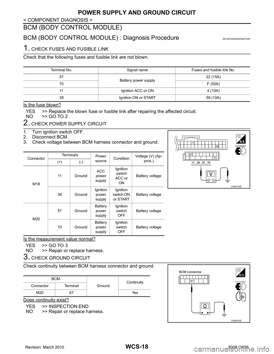
2. CHECK POWER SUPPLY CIRCUIT
1. Turn ignition switch OFF.
2. Disconnect BCM.
3. Check voltage between BCM harness connector and ground.
Is the measurement value normal?
YES >> GO TO 3
NO >> Repair or replace harness.
3. CHECK GROUND CIRCUIT
Check continuity between BCM harness connector and ground.
Does continuity exist?
YES >> INSPECTION END
NO >> Repair or replace harness.
Terminal No. Signal nameFuses and fusible link No.
57 Battery power supply 22 (15A)
70 F (50A)
11 Ignition ACC or ON 4 (10A)
38 Ignition ON or START 59 (10A)
ConnectorTe r m i n a l s
Power
source Condition
Voltage (V) (Ap-
prox.)
(+) (-)
M18 11 Ground
ACC
power
supply Ignition
switch
ACC or ON Battery voltage
38 Ground Ignition
power
supply Ignition
switch ON or START Battery voltage
M20 57 Ground
Battery
power
supply Ignition
switch
OFF Battery voltage
70 Ground Battery
power
supply Ignition
switch OFF Battery voltage
LIIA2415E
BCM
GroundContinuity
Connector Terminal
M20 67 Yes
LIIA0915E
Revision: March 2010 2008 QX56
Page 3897 of 4083
WCS-20
< COMPONENT DIAGNOSIS >
SEAT BELT BUCKLE SWITCH SIGNAL CIRCUIT
SEAT BELT BUCKLE SWITCH SIGNAL CIRCUIT
DescriptionINFOID:0000000001697681
Transmits a seat belt buckle switch signal to the combination meter.
Component Function CheckINFOID:0000000001697682
1.CHECK COMBINATION METER INPUT SIGNAL
Select “DATA MONITOR” for “METER/M&A” and check the “SEAT BELT W/L” monitor value.
>> Inspection End.
Diagnosis ProcedureINFOID:0000000001697683
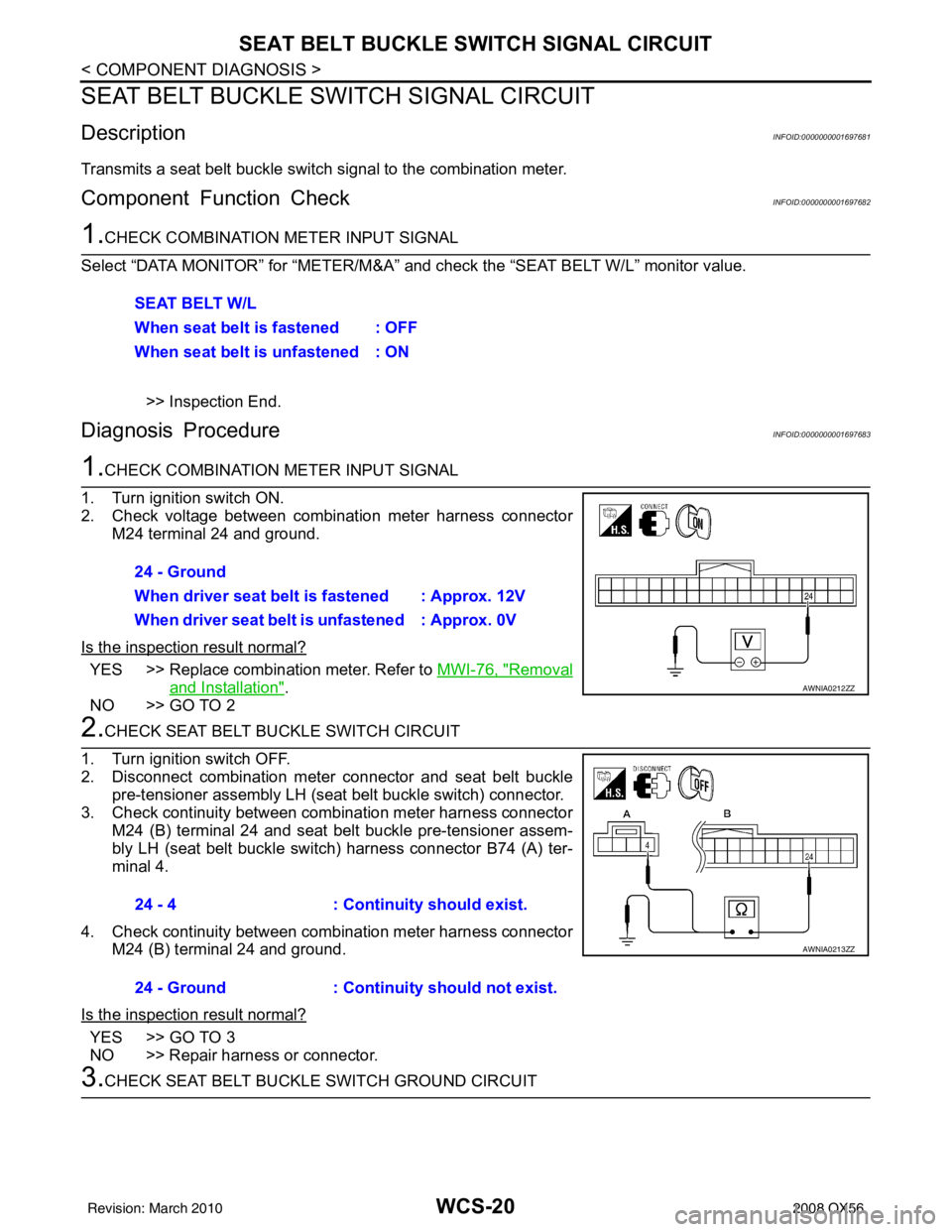
1.CHECK COMBINATION METER INPUT SIGNAL
1. Turn ignition switch ON.
2. Check voltage between combination meter harness connector M24 terminal 24 and ground.
Is the inspection result normal?
YES >> Replace combination meter. Refer to MWI-76, "Removal
and Installation".
NO >> GO TO 2
2.CHECK SEAT BELT BUCKLE SWITCH CIRCUIT
1. Turn ignition switch OFF.
2. Disconnect combination meter connector and seat belt buckle pre-tensioner assembly LH (seat belt buckle switch) connector.
3. Check continuity between combination meter harness connector M24 (B) terminal 24 and seat belt buckle pre-tensioner assem-
bly LH (seat belt buckle switch) harness connector B74 (A) ter-
minal 4.
4. Check continuity between combination meter harness connector M24 (B) terminal 24 and ground.
Is the inspection result normal?
YES >> GO TO 3
NO >> Repair harness or connector.
3.CHECK SEAT BELT BUCKLE SWITCH GROUND CIRCUIT SEAT BELT W/L
When seat belt is fastened : OFF
When seat belt is unfastened : ON
24 - Ground
When driver seat belt is fastened : Approx. 12V
When driver seat belt is unfastened : Approx. 0V
AWNIA0212ZZ
24 - 4
: Continuity should exist.
24 - Ground : Continuity should not exist.
AWNIA0213ZZ
Revision: March 2010 2008 QX56