2008 INFINITI QX56 turn signal
[x] Cancel search: turn signalPage 3499 of 4083

ST-8
< FUNCTION DIAGNOSIS >
HEATED STEERING WHEEL
Component Description
INFOID:0000000001696237
Heated steering wheel switch • Controls the heated steering relay and operates the heated steering system.
• Turns the indicator lamp ON when the system is activated.
Heated steering relay • Operates the heated steering system with the control signal from the heated steering
wheel switch.
Heated steering wheel • Heats the heating element with the power supplied from the heated steering relay.
Revision: March 2010 2008 QX56
Page 3538 of 4083

STARTING SYSTEMSTR-9
< FUNCTION DIAGNOSIS >
C
DE
F
G H
I
J
K L
M A
STR
NP
O
Component DescriptionINFOID:0000000001696227
Component part
Description
TCM TCM supplies power to the starter relay inside the IPDM E/R
when the selector lever is shifted to the P or N position.
BCM BCM sends a starter request signal to the CPU of the IPDM E/R
over the CAN communication lines.
IPDM E/R CPU inside IPDM E/R operates the starter relay at the request of
the BCM over the CAN communication lines.
Starter motor The starter motor plunger closes and the motor is supplied with
battery power, which in turn cranks the engine, when the “S” ter-
minal is supplied with electric power.
Revision: March 2010
2008 QX56
Page 3550 of 4083

TM-3
CEF
G H
I
J
K L
M A
B
TM
N
O P
P1752 INPUT CLUTCH SOLENOID .............. ....80
Description .......................................................... ....80
CONSULT-III Reference Value in Data Monitor
Mode ................................................................... ....
80
On Board Diagnosis Logic ......................................80
Possible Cause .......................................................80
DTC Confirmation Procedure ..................................80
Diagnosis Procedure ...............................................80
P1757 FRONT BRAKE SOLENOID ...................82
Description .......................................................... ....82
CONSULT-III Reference Value in Data Monitor
Mode ................................................................... ....
82
On Board Diagnosis Logic ......................................82
Possible Cause .......................................................82
DTC Confirmation Procedure ..................................82
Diagnosis Procedure ...............................................82
P1762 DIRECT CLUTCH SOLENOID ................84
Description .......................................................... ....84
CONSULT-III Reference Value in Data Monitor
Mode ................................................................... ....
84
On Board Diagnosis Logic ......................................84
Possible Cause .......................................................84
DTC Confirmation Procedure ..................................84
Diagnosis Procedure ...............................................84
P1767 HIGH AND LOW REVERSE CLUTCH
SOLENOID .........................................................
86
Description .......................................................... ....86
CONSULT-III Reference Value in Data Monitor
Mode ................................................................... ....
86
On Board Diagnosis Logic ......................................86
Possible Cause .......................................................86
DTC Confirmation Procedure ..................................86
Diagnosis Procedure ...............................................86
P1772 LOW COAST BRAKE SOLENOID .........88
Description .......................................................... ....88
CONSULT-III Reference Value in Data Monitor
Mode ................................................................... ....
88
On Board Diagnosis Logic ......................................88
Possible Cause .......................................................88
DTC Confirmation Procedure ..................................88
Diagnosis Procedure ...............................................88
P1774 LOW COAST BRAKE SOLENOID .........90
Description .......................................................... ....90
CONSULT-III Reference Value in Data Monitor
Mode ................................................................... ....
90
On Board Diagnosis Logic ......................................90
Possible Cause .......................................................90
DTC Confirmation Procedure ..................................90
Diagnosis Procedure ...............................................90
MAIN POWER SUPPLY AND GROUND CIR-
CUIT ....................................................................
92
Diagnosis Procedure ........................................... ....92
CLOSED THROTTLE POSITION AND WIDE
OPEN THROTTLE POSITION CIRCUIT ...........
94
CONSULT-III Reference Value in Data Monitor
Mode .................................................................... ....
94
Diagnosis Procedure ...............................................94
BRAKE SIGNAL CIRCUIT ................................95
CONSULT-III Reference Va lue in Data Monitor
Mode .................................................................... ....
95
Diagnosis Procedure ...............................................95
TOW MODE SWITCH .......................................96
Description ...............................................................96
Diagnosis Procedure ...............................................96
A/T SHIFT LOCK SYSTEM ...............................97
Wiring Diagram - A/T Shift Lock System .................97
Terminals And Reference Values ..........................100
Component Description ....................................... ..100
ECU DIAGNOSIS .......................................103
TCM .................................................................103
Reference Value .................................................. ..103
Wiring Diagram — A/T CONTROL SYSTEM — .. ..105
Fail-Safe .............................................................. ..114
DTC Inspection Priority Chart ................................116
DTC No. Index .......................................................116
DTC Alphabetical Index .........................................117
SYMPTOM DIAGNOSIS ............................118
SYSTEM SYMPTOM .......................................118
A/T Check Indicator Lamp Does Not Come On ... ..118
Engine Cannot Be Started in "P" or "N" Position ...118
In "P" Position, Vehicle Moves When Pushed .......119
In "N" Position, Vehicle Moves ..............................119
Large Shock("N" to "D" Position) ...........................121
Vehicle Does Not Creep Backward in "R" Position ..123
Vehicle Does Not Creep Forward in "D" Position ..125
Vehicle Cannot Be Started from D1 ......................128
A/T Does Not Shift: D1→D2 ..................................130
A/T Does Not Shift: D2→ D3 ..................................131
A/T Does Not Shift: D3→ D4 ..................................133
A/T Does Not Shift: D4→ D5 ..................................135
A/T Does Not Perform Lock-up ........................... ..137
A/T Does Not Hold Lock-up Condition ...................139
Lock-up Is Not Released .......................................140
Engine Speed Does Not Return to Idle .................141
A/T Does Not Shift: 5GR → 4GR ........................ ..142
A/T Does Not Shift: 4GR → 3GR ........................ ..144
A/T Does Not Shift: 3GR → 2GR ........................ ..146
A/T Does Not Shift: 2GR → 1GR ........................ ..147
Vehicle Does Not Decelerate By Engine Brake ... ..149
Symptom Table .....................................................151
PRECAUTION ............................................173
PRECAUTIONS ...............................................173
Revision: March 2010 2008 QX56
Page 3577 of 4083
TM-30
< FUNCTION DIAGNOSIS >
ON BOARD DIAGNOSTIC (OBD) SYSTEM
ON BOARD DIAGNOSTIC (OBD) SYSTEM
IntroductionINFOID:0000000001604002
The A/T system has two self-diagnostic systems.
The first is the emission-related on board diagnostic syst em (OBD-II) performed by the TCM in combination
with the ECM. The malfunction is indicated by the MI L (malfunction indicator lamp) and is stored as a DTC in
the ECM memory but not the TCM memory.
The second is the TCM original self-diagnosis indicated by the A/T CHECK indicator lamp. The malfunction is
stored in the TCM memory. The detected items are ov erlapped with OBD-II self-diagnostic items. For detail,
refer to TM-32, "
CONSULT-III Function (TRANSMISSION)".
OBD-II Function for A/T SystemINFOID:0000000001604003
The ECM provides emission-related on board diagnostic (O BD-II) functions for the A/T system. One function
is to receive a signal from the TCM used with OBD-relat ed parts of the A/T system. The signal is sent to the
ECM when a malfunction occurs in the corresponding OBD-re lated part. The other function is to indicate a
diagnostic result by means of the MIL (malfunction indi cator lamp) on the instrument panel. Sensors, switches
and solenoid valves are used as sensing elements.
The MIL automatically illuminates in One or Two Trip Detection Logic when a malfunction is sensed in relation
to A/T system parts.
One or Two Trip Detection Logic of OBD-IIINFOID:0000000001604004
ONE TRIP DETECTION LOGIC
If a malfunction is sensed during the first test drive, the MIL will illuminate and the malfunction will be stored in
the ECM memory as a DTC. The TCM is not provided with such a memory function.
TWO TRIP DETECTION LOGIC
When a malfunction is sensed during the first test drive, it is stored in the ECM memory as a 1st trip DTC
(diagnostic trouble code) or 1st trip freeze frame data. At this point, the MIL will not illuminate. — 1st Trip
If the same malfunction as that experienced during the fi rst test drive is sensed during the second test drive,
the MIL will illuminate. — 2nd Trip
The “Trip” in the “One or Two Trip Detection Logic” means a driving mode in which self-diagnosis is performed
during vehicle operation.
OBD-II Diagnostic Trouble Code (DTC)INFOID:0000000001604005
HOW TO READ DTC AND 1ST TRIP DTC
DTC and 1st trip DTC can be read by the following methods.
( with CONSULT-III or GST) CONSULT-III or GST (Generic Scan Tool) Examples: P0705, P0720 etc.
These DTC are prescribed by SAE J2012.
(CONSULT-III also displays the malfunctioning component or system.)
• 1st trip DTC No. is the same as DTC No.
• Output of the diagnostic troubl e code indicates that the indicated circuit has a malfunction. How-
ever, in case of the Mode II and GST, they do not indicate whether the malfunction is still occurring or
occurred in the past and returned to normal.
CONSULT-III can identify them as shown below, therefore, CONSULT-III (if available) is recom-
mended.
Freeze Frame Data and 1st Trip Freeze Frame Data
The ECM has a memory function, which stores the driv ing condition such as fuel system status, calculated
load value, engine coolant temperatur e, short term fuel trim, long term fuel trim, engine speed and vehicle
speed at the moment the ECM detects a malfunction.
Data which are stored in the ECM memory, along with the 1st trip DTC, are called 1st trip freeze frame data,
and the data, stored together with the DTC data, are called freeze frame data and displayed on CONSULT-III
or GST. The 1st trip freeze frame data can only be disp layed on the CONSULT-III screen, not on the GST. For
detail, refer to TM-30
.
Only one set of freeze frame data (either 1st trip freeze frame data of freeze frame data) can be stored in the
ECM. 1st trip freeze frame data is stored in the ECM memory along with the 1st trip DTC. There is no priority
for 1st trip freeze frame data and it is updated each time a different 1st trip DTC is detected. However, once
freeze frame data (2nd trip detection/MIL on) is stored in the ECM memory, 1st trip freeze frame data is no
Revision: March 2010 2008 QX56
Page 3579 of 4083
TM-32
< FUNCTION DIAGNOSIS >
DIAGNOSIS SYSTEM (TCM)
DIAGNOSIS SYSTEM (TCM)
CONSULT-III Function (TRANSMISSION)INFOID:0000000001604007
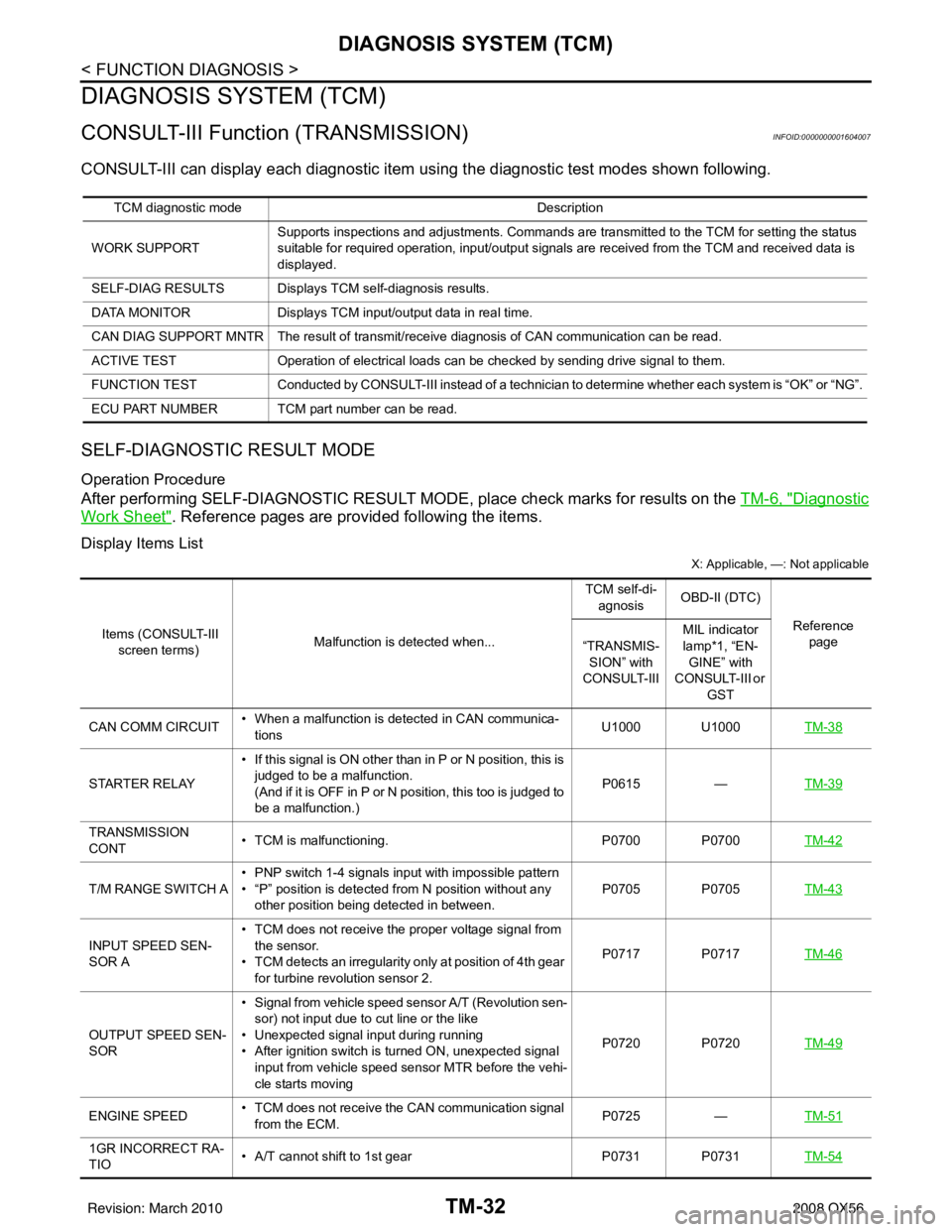
CONSULT-III can display each diagnostic item us ing the diagnostic test modes shown following.
SELF-DIAGNOSTIC RESULT MODE
Operation Procedure
After performing SELF-DIAGNOSTIC RESULT MO DE, place check marks for results on the TM-6, "Diagnostic
Work Sheet". Reference pages are provided following the items.
Display Items List
X: Applicable, —: Not applicable
TCM diagnostic mode Description
WORK SUPPORT Supports inspections and adjustments. Commands are transmitted to the TCM for setting the status
suitable for required operation, input/output signals are received from the TCM and received data is
displayed.
SELF-DIAG RESULTS Displays TCM self-diagnosis results.
DATA MONITOR Displays TCM input/output data in real time.
CAN DIAG SUPPORT MNTR The result of transmit/receive diagnosis of CAN communication can be read.
ACTIVE TEST Operation of electrical loads can be checked by sending drive signal to them.
FUNCTION TEST Conducted by CONSULT-III instead of a technici an to determine whether each system is “OK” or “NG”.
ECU PART NUMBER TCM part number can be read.
Items (CONSULT-III screen terms) Malfunction is detected when... TCM self-di-
agnosis OBD-II (DTC)
Reference page
“TRANSMIS-
SION” with
CONSULT-III MIL indicator
lamp*1, “EN-
GINE” with
CONSULT-III or GST
CAN COMM CIRCUIT • When a malfunction is detected in CAN communica-
tions U1000 U1000
TM-38
STARTER RELAY• If this signal is ON other than in P or N position, this is
judged to be a malfunction.
(And if it is OFF in P or N position, this too is judged to
be a malfunction.) P0615
—TM-39
TRANSMISSION
CONT • TCM is malfunctioning.
P0700 P0700TM-42
T/M RANGE SWITCH A• PNP switch 1-4 signals input with impossible pattern
• “P” position is detected from N position without any
other position being detected in between. P0705 P0705
TM-43
INPUT SPEED SEN-
SOR A• TCM does not receive the proper voltage signal from
the sensor.
• TCM detects an irregularity only at position of 4th gear
for turbine revolution sensor 2. P0717 P0717
TM-46
OUTPUT SPEED SEN-
SOR• Signal from vehicle speed sensor A/T (Revolution sen-
sor) not input due to cut line or the like
• Unexpected signal input during running
• After ignition switch is turned ON, unexpected signal
input from vehicle speed sensor MTR before the vehi-
cle starts moving P0720 P0720
TM-49
ENGINE SPEED• TCM does not receive the CAN communication signal
from the ECM. P0725
—TM-51
1GR INCORRECT RA-
TIO • A/T cannot shift to 1st gear
P0731 P0731TM-54
Revision: March 2010 2008 QX56
Page 3589 of 4083
TM-42
< COMPONENT DIAGNOSIS >
P0700 TRANSMISSION CONTROL
P0700 TRANSMISSION CONTROL
DescriptionINFOID:0000000001604021
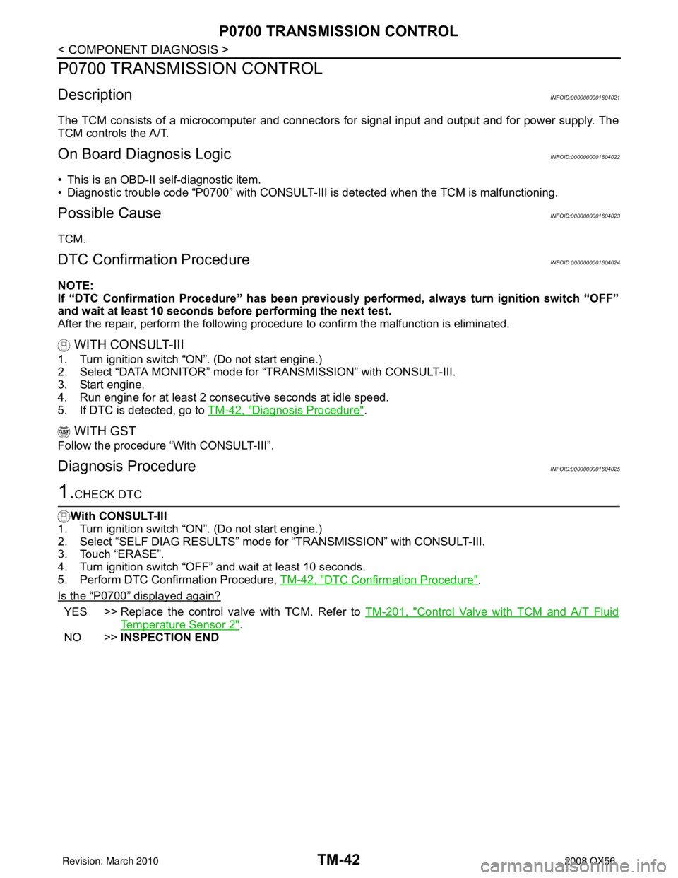
The TCM consists of a microcomputer and connectors for signal input and output and for power supply. The
TCM controls the A/T.
On Board Diagn osis LogicINFOID:0000000001604022
• This is an OBD-II self-diagnostic item.
• Diagnostic trouble code “P0700” with CONSULT-III is detected when the TCM is malfunctioning.
Possible CauseINFOID:0000000001604023
TCM.
DTC Confirmation ProcedureINFOID:0000000001604024
NOTE:
If “DTC Confirmation Procedure” has been previously performed, always turn ignition switch “OFF”
and wait at least 10 seconds before performing the next test.
After the repair, perform the following proc edure to confirm the malfunction is eliminated.
WITH CONSULT-III
1. Turn ignition switch “ON”. (Do not start engine.)
2. Select “DATA MONITOR” mode for “TRANSMISSION” with CONSULT-III.
3. Start engine.
4. Run engine for at least 2 consecutive seconds at idle speed.
5. If DTC is detected, go to TM-42, "
Diagnosis Procedure".
WITH GST
Follow the procedure “With CONSULT-III”.
Diagnosis ProcedureINFOID:0000000001604025
1.CHECK DTC
With CONSULT-III
1. Turn ignition switch “ON”. (Do not start engine.)
2. Select “SELF DIAG RESULTS” mode for “TRANSMISSION” with CONSULT-III.
3. Touch “ERASE”.
4. Turn ignition switch “OFF” and wait at least 10 seconds.
5. Perform DTC Confirmation Procedure, TM-42, "
DTC Confirmation Procedure".
Is the
“P0700” displayed again?
YES >> Replace the control valve with TCM. Refer to TM-201, "Control Valve with TCM and A/T Fluid
Temperature Sensor 2".
NO >> INSPECTION END
Revision: March 2010 2008 QX56
Page 3590 of 4083
P0705 TRANSMISSION RANGE SWITCH A
TM-43
< COMPONENT DIAGNOSIS >
C EF
G H
I
J
K L
M A
B
TM
N
O P
P0705 TRANSMISSION RANGE SWITCH A
DescriptionINFOID:0000000001604026
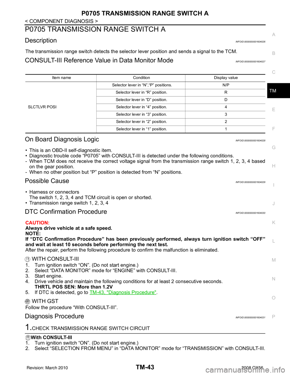
The transmission range switch detects the select or lever position and sends a signal to the TCM.
CONSULT-III Reference Value in Data Monitor ModeINFOID:0000000001604027
On Board Diagnosis LogicINFOID:0000000001604028
• This is an OBD-II self-diagnostic item.
• Diagnostic trouble code “P0705” with CONSULT-III is detected under the following conditions.
- When TCM does not receive the correct voltage signal from the transmission range switch 1, 2, 3, 4 based
on the gear position.
- When no other position but “P” positi on is detected from “N” positions.
Possible CauseINFOID:0000000001604029
• Harness or connectors
The switch 1, 2, 3, 4 and TCM circuit is open or shorted.
• Transmission range switch 1, 2, 3, 4
DTC Confirmation ProcedureINFOID:0000000001604030
CAUTION:
Always drive vehicle at a safe speed.
NOTE:
If “DTC Confirmation Procedure” has been previously performed, always turn ignition switch “OFF”
and wait at least 10 seconds before performing the next test.
After the repair, perform the following procedure to confirm the malfunction is eliminated.
WITH CONSULT-III
1. Turn ignition switch “ON”. (Do not start engine.)
2. Select “DATA MONITOR” mode for “ENGINE” with CONSULT-III.
3. Start engine.
4. Drive vehicle and maintain the following conditions for at least 2 consecutive seconds. THRTL POS SEN: More than 1.2V
5. If DTC is detected, go to TM-43, "
Diagnosis Procedure".
WITH GST
Follow the procedure “With CONSULT-III”.
Diagnosis ProcedureINFOID:0000000001604031
1.CHECK TRANSMISSION RANGE SWITCH CIRCUIT
With CONSULT-III
1. Turn ignition switch “ON”. (Do not start engine.)
2. Select “SELECTION FROM MENU” in “DATA MONI TOR” mode for “TRANSMISSION” with CONSULT-III.
Item nameCondition Display value
SLCTLVR POSI Selector lever in “N”,“P” positions.
N/P
Selector lever in “R” position. R
Selector lever in “D” position. D
Selector lever in “4” position. 4
Selector lever in “3” position. 3
Selector lever in “2” position. 2
Selector lever in “1” position. 1
Revision: March 2010 2008 QX56
Page 3593 of 4083
TM-46
< COMPONENT DIAGNOSIS >
P0717 INPUT SPEED SENSOR A
P0717 INPUT SPEED SENSOR A
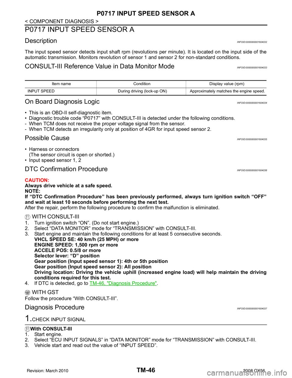
DescriptionINFOID:0000000001604032
The input speed sensor detects input shaft rpm (revolutions per minute). It is located on the input side of the
automatic transmission. Monitors revolution of sensor 1 and sensor 2 for non-standard conditions.
CONSULT-III Reference Value in Data Monitor ModeINFOID:0000000001604033
On Board Diagnosis LogicINFOID:0000000001604034
• This is an OBD-II self-diagnostic item.
• Diagnostic trouble code “P0717” with CONSULT-III is detected under the following conditions.
- When TCM does not receive the proper voltage signal from the sensor.
- When TCM detects an irregularity only at pos ition of 4GR for input speed sensor 2.
Possible CauseINFOID:0000000001604035
• Harness or connectors
(The sensor circuit is open or shorted.)
• Input speed sensor 1, 2
DTC Confirmation ProcedureINFOID:0000000001604036
CAUTION:
Always drive vehicle at a safe speed.
NOTE:
If “DTC Confirmation Procedure” has been previously performed, always turn ignition switch “OFF”
and wait at least 10 seconds before performing the next test.
After the repair, perform the following proc edure to confirm the malfunction is eliminated.
WITH CONSULT-III
1. Turn ignition switch “ON”. (Do not start engine.)
2. Select “DATA MONITOR” mode for “TRANSMISSION” with CONSULT-III.
3. Start engine and maintain the following conditions for at least 5 consecutive seconds. VHCL SPEED SE: 40 km/h (25 MPH) or more
ENGINE SPEED: 1,500 rpm or more
ACCELE POS: 0.5/8 or more
Selector lever: “D” position
Gear position (Input speed sensor 1): 4th or 5th position
Gear position (Input sp eed sensor 2): All position
Driving location: Driving the vehicle uphill (increased engine load) will help maintain the driving
conditions required for this test.
4. If DTC is detected, go to TM-46, "
Diagnosis Procedure".
WITH GST
Follow the procedure “With CONSULT-III”.
Diagnosis ProcedureINFOID:0000000001604037
1.CHECK INPUT SIGNAL
With CONSULT-III
1. Start engine.
2. Select “ECU INPUT SIGNALS” in “DATA MONI TOR” mode for “TRANSMISSION” with CONSULT-III.
3. Vehicle start and read out the value of “INPUT SPEED”.
Item name Condition Display value (rpm)
INPUT SPEED During driving (lock-up ON) Approximately matche s the engine speed.
Revision: March 2010 2008 QX56