2008 INFINITI QX56 air condition
[x] Cancel search: air conditionPage 2607 of 4083

PERIODIC MAINTENANCEMA-9
< ON-VEHICLE MAINTENANCE >
C
DE
F
G H
I
J
K L
M B
MA
N
O A
(1) After 60,000 miles (96,000 km) or 48 months, inspect every 15,000 miles (24,000 km) or 12 months. Replace drive belts if da
maged.
(2) If operating mainly in dusty conditions, more frequent maintenance may be required.
(3) Maintenance-free item. For service procedures, go to the FL section.
(4) After 60,000 miles (96,000 km) or 48 months, replace every 30,000 miles (48,000 km) or 24 months.
(5) If valve noise increases, inspect valve clearance.
* Maintenance items and inte rvals with “*” are recommended by NISSAN for reliable vehicle operation. The owner need not perform
such maintenance in order to maintain the emission warranty or manufacturer recall liability. Other maintenance items and inter vals are
required.
CHASSIS AND BODY MAINTENANCE
Abbreviations: R = Replace. I = Inspect. Correct or replace if necessary. L = Lubricate. [ ]: At the mileage intervals only.
MAINTENANCE OPERATION MAINTENANCE INTERVAL
Reference
Section -
Page or -
Content Title
Perform at number of miles, kilo-
meters or months, whichever
comes first. Miles x 1,000
(km x 1,000) Months 33.75
(54)27 37.5
(60) 30 41.25
(66)33 45
(72) 36 48.75
(78)39 52.5
(84) 42 56.25
(90)45 60
(96) 48
Drive belts NOTE (1) I*MA-14
Air cleaner filter NOTE (2) [R]MA-17
EVAP vapor lines I*MA-21
Fuel lines I*MA-17
Fuel filter NOTE (3) —
Engine coolant NOTE (4) R*MA-14
Engine oil R R R R R R R R MA-18
Engine oil filterR R R R R R R R MA-18
Spark plugs (double PLATINUM-
TIPPED type)Replace every 105,000 miles (169,000 km).
MA-20
Intake and exhaust valve clear-
ance*NOTE (5)
EM-108
MAINTENANCE OPERATIONMAINTENANCE INTERVAL
Reference
Section- Page
or
- Content Title
Perform at number of miles, kilometers or
months, whichever comes first. Miles x
1,000(km x
1,000)
Months 3.75
(6)3 7.5
(12) 6 11 . 2 5
(18) 9 15
(24) 12 18.75
(30)15 22.5
(36) 18 26.25
(42)21 30
(48) 24
Brake lines and cables IIMA-30
Brake pads and rotors II I IMA-30
Automatic transmission fluid NOTE (1)IIMA-23
Transfer fluid and front final drive oil NOTE (1)IIMA-26,
MA-26
Rear final drive oil NOTE (1)IIMA-26
Steering gear and linkage, axle and suspension
parts II I I
MA-30,
MA-31
Tire Rotation NOTE (2) MA-29
Drive shaft boots and propeller shaft (4WD)II I IMA-26
Exhaust system II I IMA-23
In-cabin microfilter RRMA-22
Revision: March 2010 2008 QX56
Page 2610 of 4083
MA-12
< ON-VEHICLE MAINTENANCE >
RECOMMENDED FLUIDS AND LUBRICANTS
RECOMMENDED FLUIDS AND LUBRICANTS
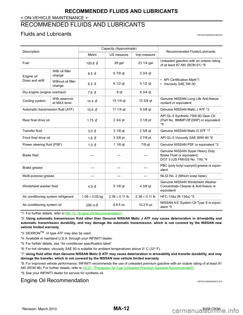
Fluids and LubricantsINFOID:0000000001606168
*1: For further details, refer to MA-12, "Engine Oil Recommendation" .
*2: Using automatic transmission fluid other than Genuine NISSAN Matic J ATF may cause deterioration in driveability and
automatic transmission durability, and may damage the automatic transmission, which is not covered by the NISSAN new
vehicle limited warranty.
*3: DEXRON
TM VI type ATF may also be used.
*4: Available in mainland U.S.A. through your INFINITI dealer.
*5: For further details, see “Air conditioner specification label”.
*6: For hot climates, viscosity SAE 90 is suitable for ambient te mperatures above 0° C (32 ° F).
*7: Using fluid other than Genuine NISSAN Matic D ATF may cause de terioration in driveability and transfer durability, and may
damage the transfer, which is not covered by the NISSAN new vehicle limited warranty.
*8: For improved vehicle performance, INFINITI recommends the use of unleaded premium gasoline with an octane rating of at leas t 91
AKI (RON 96). For further details, refer to GI-27, "
Precaution for Fuel (Unleaded Premium Gasoline Recommended)".
*9: See your INFINITI dealer for service for synthetic oil.
Engine Oil RecommendationINFOID:0000000006211816
Description Capacity (Approximate)
Recommended Fluids/Lubricants
Metric US measure Imp measure
Fuel 105.8 28 gal 23 1/4 gal Unleaded gasoline with an octane rating
of at least 87 AKI (RON 91) *8
Engine oil
Drain and refill With oil filter
change
6.5
6 7/8 qt 5 3/4 qt
• API Certification Mark*1
• Viscosity SAE 5W-30
Without oil filter
change
6.2
6 1/2 qt 5 1/2 qt
Dry engine (engine overhaul) 7.6 8 qt
6 3/4 qt
Cooling system With reservoir
at MAX level
14.4
15 1/4 qt 12 5/8 qt Genuine NISSAN Long Life Anti-freeze
coolant or equivalent
Automatic transmission fluid (ATF) 10.6 11 1/4 qt 9 3/8 qt Genuine NISSAN Matic J ATF *2
Rear final drive oil 1.75 3 3/4 pt 3 1/8 pt API GL-5 Synthetic 75W-90 Gear Oil
(Part No. 999MP-DF200P) or equivalent
*9
Transfer fluid 3.0 3 1/8 qt 2 5/8 qt Genuine NISSAN Matic D ATF *7
Front final drive oil 1.6 3 3/8 pt 2 7/8 pt API GL-5 Viscosity SAE 80W-90 *6
Power steering fluid (PSF) 1.0 1 1/8 qt 7/8 qt Genuine NISSAN PSF or equivalent *3
Brake fluid —— —Genuine NISSAN Super Heavy Duty
Brake Fluid or equivalent,
DOT 3 (US FMVSS No. 116) *4
Brake grease —— —PBC (poly butyl cuprysil) grease or equiv-
alent
Multi-purpose grease —— — NLGI No. 2 (lithium soap base)
Windshield washer fluid 4.9 5 1/8 qt 4 3/8 qt Genuine NISSAN Windshield Washer
Concentrate Cleaner & Anti-freeze or
equivalent
Air conditioning system refrigerant 1.08 ± 0.05 kg 2.38 ± 0.11 lb 2.38 ± 0.11 lb HFC-134a (R-134a) *5
Air conditioning system oil 290 m9.8 fl oz 10.2 fl oz NISSAN A/C System Oil Type S or equiv-
alent *5
Revision: March 2010
2008 QX56
Page 2622 of 4083
MA-24
< ON-VEHICLE MAINTENANCE >
CHASSIS AND BODY MAINTENANCE
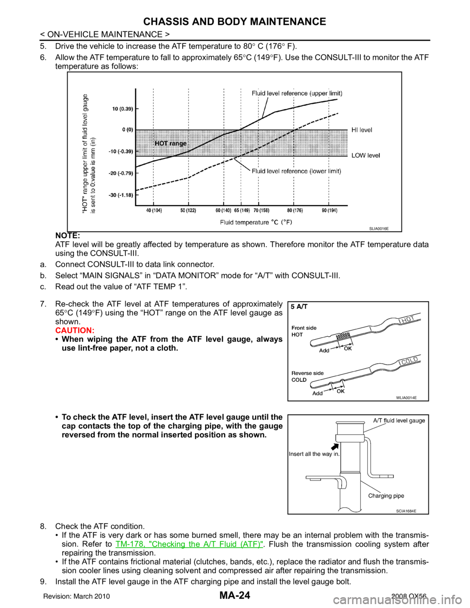
5. Drive the vehicle to increase the ATF temperature to 80° C (176 ° F).
6. Allow the ATF temperature to fall to approximately 65 °C (149° F). Use the CONSULT-III to monitor the ATF
temperature as follows:
NOTE:
ATF level will be greatly affected by temperature as shown. Therefore monitor the ATF temperature data
using the CONSULT-III.
a. Connect CONSULT-III to data link connector.
b. Select “MAIN SIGNALS” in “DATA MONI TOR” mode for “A/T” with CONSULT-III.
c. Read out the value of “ATF TEMP 1”.
7. Re-check the ATF level at ATF temperatures of approximately 65°C (149° F) using the “HOT” range on the ATF level gauge as
shown.
CAUTION:
• When wiping the ATF from the ATF level gauge, always use lint-free paper, not a cloth.
• To check the ATF level, insert the ATF level gauge until the cap contacts the top of the ch arging pipe, with the gauge
reversed from the normal inserted position as shown.
8. Check the ATF condition. • If the ATF is very dark or has some burned smell, there may be an internal problem with the transmis-
sion. Refer to TM-178, "
Checking the A/T Fluid (ATF)". Flush the transmission cooling system after
repairing the transmission.
• If the ATF contains frictional material (clutches, bands , etc.), replace the radiator and flush the transmis-
sion cooler lines using cleaning solvent and compressed air after repairing the transmission.
9. Install the ATF level gauge in the ATF charging pipe and install the level gauge bolt.
SLIA0016E
WLIA0014E
SCIA1684E
Revision: March 2010 2008 QX56
Page 2628 of 4083
MA-30
< ON-VEHICLE MAINTENANCE >
CHASSIS AND BODY MAINTENANCE
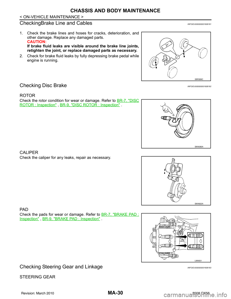
CheckingBrake Line and Cables
INFOID:0000000001606191
1. Check the brake lines and hoses for cracks, deterioration, and other damage. Replace any damaged parts.
CAUTION:
If brake fluid leaks are visible around the brake line joints,
retighten the joint, or replace damaged parts as necessary.
2. Check for brake fluid leaks by fully depressing brake pedal while engine is running.
Checking Disc BrakeINFOID:0000000001606192
ROTOR
Check the rotor condition for wear or damage. Refer to BR-7, "DISC
ROTOR : Inspection" , BR-9, "DISC ROTOR : Inspection" .
CALIPER
Check the caliper for any l eaks, repair as necessary.
PA D
Check the pads for wear or damage. Refer to BR-7, "BRAKE PAD :
Inspection" , BR-9, "BRAKE PAD : Inspection" .
Checking Steering Gear and LinkageINFOID:0000000001606193
STEERING GEAR
SBR389C
SMA260A
SMA922A
LMA051
Revision: March 2010 2008 QX56
Page 2648 of 4083
MWI
MWI-3
C
DE
F
G H
I
J
K L
M B
A
O P
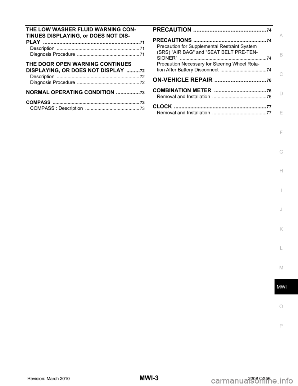
THE LOW WASHER FLUID WARNING CON-
TINUES DISPLAYING, or DOES NOT DIS-
PLAY .............................................................. ....
71
Description .......................................................... ....71
Diagnosis Procedure ...............................................71
THE DOOR OPEN WARNING CONTINUES
DISPLAYING, OR DOES NOT DISPLAY ..........
72
Description .......................................................... ....72
Diagnosis Procedure ...............................................72
NORMAL OPERATING CONDITION .................73
COMPASS ............................................................. ....73
COMPASS : Description .........................................73
PRECAUTION ...... ........................................74
PRECAUTIONS .................................................74
Precaution for Supplemental Restraint System
(SRS) "AIR BAG" and "SEAT BELT PRE-TEN-
SIONER" ............................................................. ....
74
Precaution Necessary for Steering Wheel Rota-
tion After Battery Disconnect ...................................
74
ON-VEHICLE REPAIR .................................76
COMBINATION METER ...................................76
Removal and Installation ..................................... ....76
CLOCK ..............................................................77
Removal and Installation .........................................77
Revision: March 2010 2008 QX56
Page 2671 of 4083
![INFINITI QX56 2008 Factory Service Manual MWI-26
< FUNCTION DIAGNOSIS >
DIAGNOSIS SYSTEM (METER)
X: Applicable
Display item [Unit]MAIN
SIGNALS SELECTION
FROM MENU Description
SPEED METER [km/h] or [mph] X X Displays the value of vehicle spee INFINITI QX56 2008 Factory Service Manual MWI-26
< FUNCTION DIAGNOSIS >
DIAGNOSIS SYSTEM (METER)
X: Applicable
Display item [Unit]MAIN
SIGNALS SELECTION
FROM MENU Description
SPEED METER [km/h] or [mph] X X Displays the value of vehicle spee](/manual-img/42/57030/w960_57030-2670.png)
MWI-26
< FUNCTION DIAGNOSIS >
DIAGNOSIS SYSTEM (METER)
X: Applicable
Display item [Unit]MAIN
SIGNALS SELECTION
FROM MENU Description
SPEED METER [km/h] or [mph] X X Displays the value of vehicle speed signal.
SPEED OUTPUT [km/h] or [mph] X XDisplays the value of vehicle speed signal, which is transmitted to
each unit with
CAN communication.
TACHO METER [rpm] XX Displays the value of engine speed signal, which is input from ECM.
FUEL METER [lit.] XXDisplays the value, which processes a resistance signal from fuel
gauge.
W TEMP METER [ °C] or [° F] X XDisplays the value of engine coolant temperature signal, which is in-
put from ECM.
ABS W/L [ON/OFF] X Displays [ON/OFF] condition of ABS warning lamp.
VDC/TCS IND [ON/OFF] X Displays [ON/OFF] condition of VDC OFF indicator lamp.
SLIP IND [ON/OFF] X Displays [ON/OFF] condition of SLIP indicator lamp.
BRAKE W/L [ON/OFF] X Displays [ON/OFF] condition of brake warning lamp.*
DOOR W/L [ON/OFF] X Displays [ON/OFF] condition of door warning lamp.
TRUNK W/L [ON/OFF] X Displays [ON/OFF] condition of glass hatch warning lamp.
HI-BEAM IND [ON/OFF] X Displays [ON/OFF] condition of high beam indicator.
TURN IND [ON/OFF] X Displays [ON/OFF] conditio n of turn indicator.
OIL W/L [ON/OFF] X Displays [ON/OFF] condition of oil pressure warning lamp.
C-ENG W/L [ON/OFF] X Displays [ON/OFF] condition of malfunction indicator lamp.
CRUISE IND [ON/OFF] X Displays [ON/OFF] condition of CRUISE indicator.
SET IND [ON/OFF] X Displays [ON/OFF] condition of SET indicator.
AT CHECK W/L [ON/OFF] X Displays [ON/OFF] condition of AT CHECK warning lamp.
FUEL W/L [ON/OFF] XX Displays [ON/OFF] condition of low-fuel warning lamp.
AIR PRES W/L [ON/OFF] X Displays [ON/OFF] condition of tire pressure warning lamp.
KEY G W/L [ON/OFF] X Displays [ON/OFF] condition of key green warning lamp.
KEY R W/L [ON/OFF] X Displays [ON/OFF] condition of key red warning lamp.
KEY KNOB W/L [ON/OFF] X Displays [ON/OFF] condition of key knob warning lamp.
M RANGE SW [ON/OFF] XX Displays [ON/OFF] condition of manual mode range switch.
NM RANGE SW [ON/OFF] XXDisplays [ON/OFF] condition of except for manual mode range
switch.
AT SFT UP SW [ON/OFF] XX Displays [ON/OFF] condition of A/T shift-up switch.
AT SFT DWN SW [ON/OFF] XX Displays [ON/OF F] condition of A/T shift-down switch.
DISTANCE [km] or [mile] XXDisplays the value, which is calculated by vehicle speed signal, fuel
gauge and fuel consumption from ECM.
BUZZER [ON/OFF] XX Displays [ON/ OFF] condition of buzzer.
BRAKE SW [ON/OFF] X Indicates [ON/OFF] condition of parking brake switch.
AT-M GEAR [1, 2, 3, 4, 5] XX Indicates [1, 2, 3, 4, 5] condition of A/T manual mode gear position.
P RANGE IND [ON/OFF] XX Indicates [ON/OFF] condition of A/T shift P range indicator.
R RANGE IND [ON/OFF] XX Indicates [ON/OFF] condition of A/T shift R range indicator.
N RANGE IND [ON/OFF] XX Indicates [ON/OFF] condition of A/T shift N range indicator.
D RANGE IND [ON/OFF] XX Indicates [ON/OFF] condition of A/T shift D range indicator.
4 RANGE IND [ON/OFF] XX Indicates [ON/OFF] condition of A/T shift 4 range indicator.
3 RANGE IND [ON/OFF] XX Indicates [ON/OFF] condition of A/T shift 3 range indicator.
2 RANGE IND [ON/OFF] XX Indicates [ON/OFF] condition of A/T shift 2 range indicator.
1 RANGE IND [ON/OFF] XX Indicates [ON/OFF] condition of A/T shift 1range indicator.
Revision: March 2010 2008 QX56
Page 2676 of 4083
MWI
POWER SUPPLY AND GROUND CIRCUITMWI-31
< COMPONENT DIAGNOSIS >
C
DE
F
G H
I
J
K L
M B A
O P
BCM (BODY CONTROL MODULE) : Diagnosis ProcedureINFOID:0000000001696511
1. CHECK FUSES AND FUSIBLE LINK
Check that the following fuses and fusible link are not blown.
Is the fuse blown?
YES >> Replace the blown fuse or fusible link after repairing the affected circuit.
NO >> GO TO 2
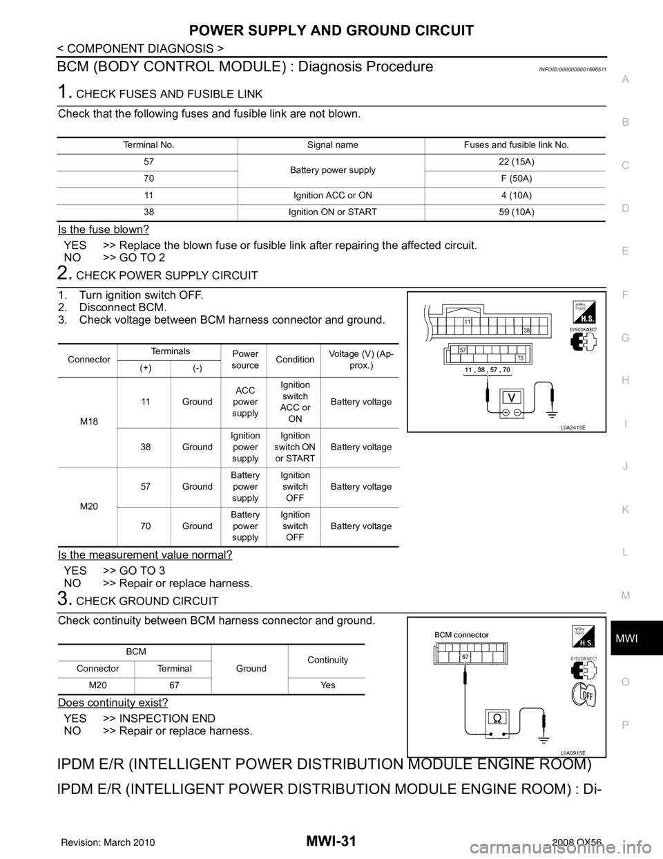
2. CHECK POWER SUPPLY CIRCUIT
1. Turn ignition switch OFF.
2. Disconnect BCM.
3. Check voltage between BCM harness connector and ground.
Is the measurement value normal?
YES >> GO TO 3
NO >> Repair or replace harness.
3. CHECK GROUND CIRCUIT
Check continuity between BCM harness connector and ground.
Does continuity exist?
YES >> INSPECTION END
NO >> Repair or replace harness.
IPDM E/R (INTELLIGENT POWER DIST RIBUTION MODULE ENGINE ROOM)
IPDM E/R (INTELLIGENT POWER DISTRIBUTION MODULE ENGINE ROOM) : Di-
Terminal No. Signal nameFuses and fusible link No.
57 Battery power supply 22 (15A)
70 F (50A)
11 Ignition ACC or ON 4 (10A)
38 Ignition ON or START 59 (10A)
ConnectorTe r m i n a l s
Power
source Condition Voltage (V) (Ap-
prox.)
(+) (-)
M18 11 Ground
ACC
power
supply Ignition
switch
ACC or
ON Battery voltage
38 Ground Ignition
power
supply Ignition
switch ON or START Battery voltage
M20 57 Ground
Battery
power
supply Ignition
switch OFF Battery voltage
70 Ground Battery
power
supply Ignition
switch
OFF Battery voltage
LIIA2415E
BCM
GroundContinuity
Connector Terminal
M20 67 Yes
LIIA0915E
Revision: March 2010 2008 QX56
Page 2679 of 4083
MWI-34
< COMPONENT DIAGNOSIS >
FUEL LEVEL SENSOR SIGNAL CIRCUIT
3.CHECK FUEL LEVEL SENSOR UNIT GROUND CIRCUIT
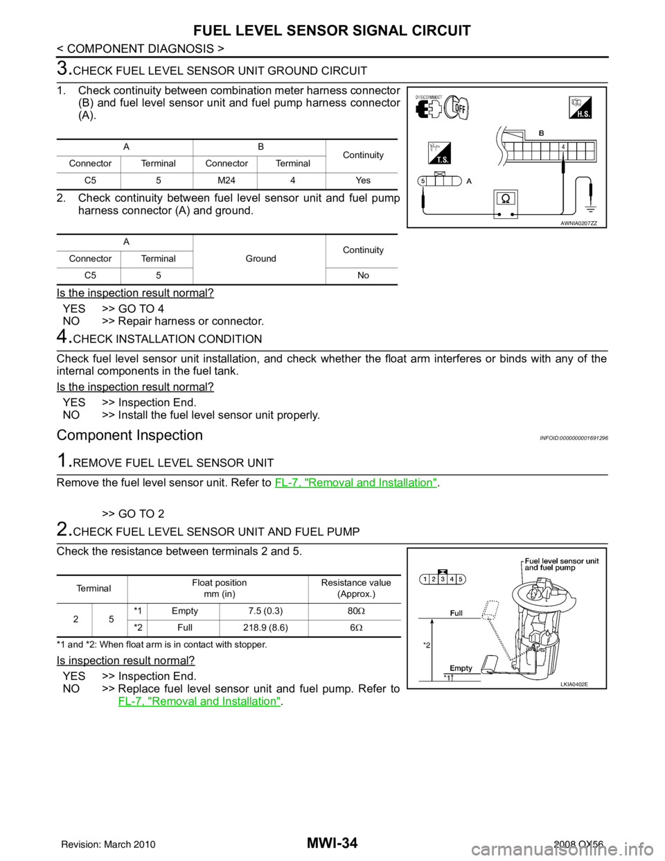
1. Check continuity between combination meter harness connector (B) and fuel level sensor uni t and fuel pump harness connector
(A).
2. Check continuity between fuel level sensor unit and fuel pump harness connector (A) and ground.
Is the inspection result normal?
YES >> GO TO 4
NO >> Repair harness or connector.
4.CHECK INSTALLATION CONDITION
Check fuel level sensor unit installation, and check whether the float arm interferes or binds with any of the
internal components in the fuel tank.
Is the inspection result normal?
YES >> Inspection End.
NO >> Install the fuel level sensor unit properly.
Component InspectionINFOID:0000000001691296
1.REMOVE FUEL LEVEL SENSOR UNIT
Remove the fuel level sensor unit. Refer to FL-7, "
Removal and Installation".
>> GO TO 2
2.CHECK FUEL LEVEL SENSOR UNIT AND FUEL PUMP
Check the resistance between terminals 2 and 5.
*1 and *2: When float arm is in contact with stopper.
Is inspection result normal?
YES >> Inspection End.
NO >> Replace fuel level sensor unit and fuel pump. Refer to FL-7, "
Removal and Installation".
AB Continuity
Connector Terminal Connector Terminal
C5 5 M24 4 Yes
A GroundContinuity
Connector Terminal
C5 5 No
AWNIA0207ZZ
Te r m i n a l Float position
mm (in) Resistance value
(Approx.)
25 *1 Empty
7.5 (0.3)80Ω
*2 Full 218.9 (8.6)6Ω
LKIA0402E
Revision: March 2010 2008 QX56