Page 1836 of 4083
OIL PAN AND OIL STRAINEREM-33
< ON-VEHICLE REPAIR >
C
DE
F
G H
I
J
K L
M A
EM
NP
O
OIL PAN AND OIL STRAINER
Removal and InstallationINFOID:0000000001538816
REMOVAL
WARNING:
To avoid the danger of being scalded, never drain the engine oil when the engine is hot.
1. Remove the engine. Refer to
EM-78, "
Removal and Installation".
2. Remove the oil pan (lower) using the following steps.
a. Remove the oil pan (lower) bolts using power tool.
1. Oil pan (upper) 2. O-ring3. O-ring
4. O-ring 5. O-ring (with collar)6. Oil level gauge guide
7. Oil level gauge 8. O-ring9. Connector bolt
10. Oil filter 11. Oil cooler12. Relief valve
13. Oil pressure switch 14. Gasket15. Drain plug
16. Oil pan (lower) 17. Oil strainer
KBIA2465E
KBIA2466E
Revision: March 2010 2008 QX56
Page 1839 of 4083
EM-36
< ON-VEHICLE REPAIR >
OIL PAN AND OIL STRAINER
4. Install the oil pan drain plug.
5. Install engine assembly. Refer to EM-78, "
Removal and Installation".
• Do not fill the engine oil for at least 30 minutes after oil pan is installed.
INSPECTION AFTER INSTALLATION
1. Check engine oil level and add engine oil if necessary. Refer to LU-8, "Inspection".
2. Start the engine, and check for leaks of engine oil.
3. Stop engine and wait for 10 minutes.
4. Check engine oil level again.
Revision: March 2010 2008 QX56
Page 1840 of 4083
IGNITION COILEM-37
< ON-VEHICLE REPAIR >
C
DE
F
G H
I
J
K L
M A
EM
NP
O
IGNITION COIL
Removal and InstallationINFOID:0000000001538817
REMOVAL
1. Remove the engine room cover using power tool. Refer to
EM-24, "Removal and Installation" .
2. Disconnect the harness connector from the ignition coil.
3. Remove the ignition coil. CAUTION:
Do not shock ignition coil.
INSTALLATION
Installation is in the reverse order of removal.
1. Ignition coil 2. Spark plug
WBIA0796E
Revision: March 2010 2008 QX56
Page 1841 of 4083

EM-38
< ON-VEHICLE REPAIR >
ROCKER COVER
ROCKER COVER
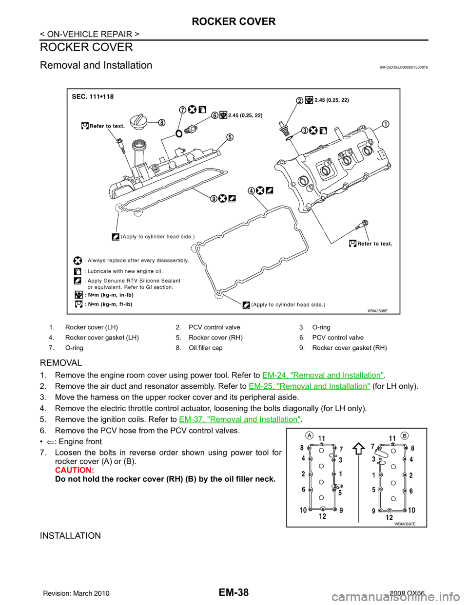
Removal and InstallationINFOID:0000000001538818
REMOVAL
1. Remove the engine room cover using power tool. Refer to EM-24, "Removal and Installation".
2. Remove the air duct and resonator assembly. Refer to EM-25, "
Removal and Installation" (for LH only).
3. Move the harness on the upper rocker cover and its peripheral aside.
4. Remove the electric throttle control actuat or, loosening the bolts diagonally (for LH only).
5. Remove the ignition coils. Refer to EM-37, "
Removal and Installation".
6. Remove the PCV hose from the PCV control valves.
• ⇐ : Engine front
7. Loosen the bolts in reverse order shown using power tool for rocker cover (A) or (B).
CAUTION:
Do not hold the rocker cover ( RH) (B) by the oil filler neck.
INSTALLATION
1. Rocker cover (LH) 2. PCV control valve3. O-ring
4. Rocker cover gasket (LH) 5. Rocker cover (RH)6. PCV control valve
7. O-ring 8. Oil filler cap9. Rocker cover gasket (RH)
KBIA2508E
WBIA0697E
Revision: March 2010 2008 QX56
Page 1843 of 4083
EM-40
< ON-VEHICLE REPAIR >
FUEL INJECTOR AND FUEL TUBE
FUEL INJECTOR AND FUEL TUBE
Removal and InstallationINFOID:0000000001538819
CAUTION:
Do not remove or disassemble parts unless instructed as shown.
REMOVAL
1. Remove engine room cover using power tool. Refer to EM-24, "Removal and Installation".
2. Release fuel pressure. Refer to EC-494, "
Fuel Pressure Check".
3. Disconnect the negative battery terminal.
4. Disconnect fuel injector harness connectors.
5. Disconnect fuel hose assembly from fuel tube (RH bank and LH bank). CAUTION:
• While hoses are disconnected, plug th em to prevent fuel from draining.
• Do not separate fuel co nnector and fuel hose.
6. Remove fuel injectors with fuel tube assembly.
1. Fuel tube (RH bank) 2. Cap3. Fuel damper
4. O-ring 5. O-ring (Blue)6. Fuel injector
7. Clip 8. O-ring (Brown)9. O-ring
10. Fuel hose assembly 11. Fuel tube (LH bank)
KBIA2472E
Revision: March 2010 2008 QX56
Page 1844 of 4083

FUEL INJECTOR AND FUEL TUBEEM-41
< ON-VEHICLE REPAIR >
C
DE
F
G H
I
J
K L
M A
EM
NP
O
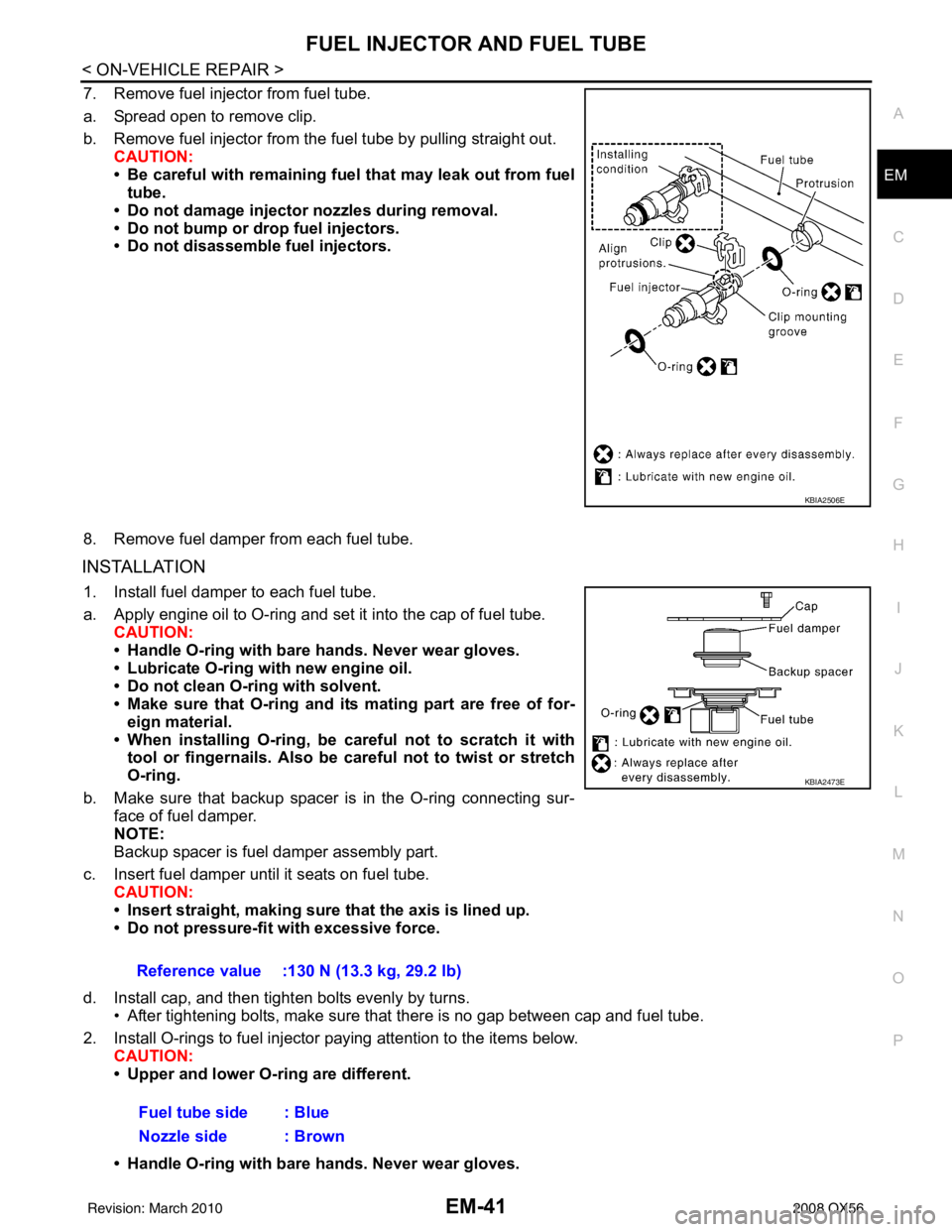
7. Remove fuel injector from fuel tube.
a. Spread open to remove clip.
b. Remove fuel injector from the
fuel tube by pulling straight out.
CAUTION:
• Be careful with remaining fuel that may leak out from fuel
tube.
• Do not damage injector nozzles during removal.
• Do not bump or drop fuel injectors.
• Do not disassemble fuel injectors.
8. Remove fuel damper from each fuel tube.
INSTALLATION
1. Install fuel damper to each fuel tube.
a. Apply engine oil to O-ring and set it into the cap of fuel tube. CAUTION:
• Handle O-ring with bare hands. Never wear gloves.
• Lubricate O-ring with new engine oil.
• Do not clean O-ring with solvent.
• Make sure that O-ring and its mating part are free of for- eign material.
• When installing O-ring, be car eful not to scratch it with
tool or fingernails. Also be careful not to twist or stretch
O-ring.
b. Make sure that backup spacer is in the O-ring connecting sur- face of fuel damper.
NOTE:
Backup spacer is fuel damper assembly part.
c. Insert fuel damper until it seats on fuel tube. CAUTION:
• Insert straight, making sure that the axis is lined up.
• Do not pressure-fit with excessive force.
d. Install cap, and then tighten bolts evenly by turns. • After tightening bolts, make sure that there is no gap between cap and fuel tube.
2. Install O-rings to fuel injector paying attention to the items below. CAUTION:
• Upper and lower O-ring are different.
• Handle O-ring with bare hands. Never wear gloves.
KBIA2506E
Reference value :130 N (13.3 kg, 29.2 lb)
Fuel tube side : Blue
Nozzle side : Brown
KBIA2473E
Revision: March 2010 2008 QX56
Page 1845 of 4083

EM-42
< ON-VEHICLE REPAIR >
FUEL INJECTOR AND FUEL TUBE
• Lubricate O-ring with new engine oil.
• Do not clean O-ring with solvent.
• Make sure that O-ring and its mating part are free of foreign material.
• When installing O-ring, be careful not to scratch it with tool or fingernails. Also be careful not to
twist or stretch O-ring. If O-ring was stretc hed while it was being attached, do not insert it
quickly into fuel tube.
• Insert O-ring straight into fuel tube. Do not angle or twist it.
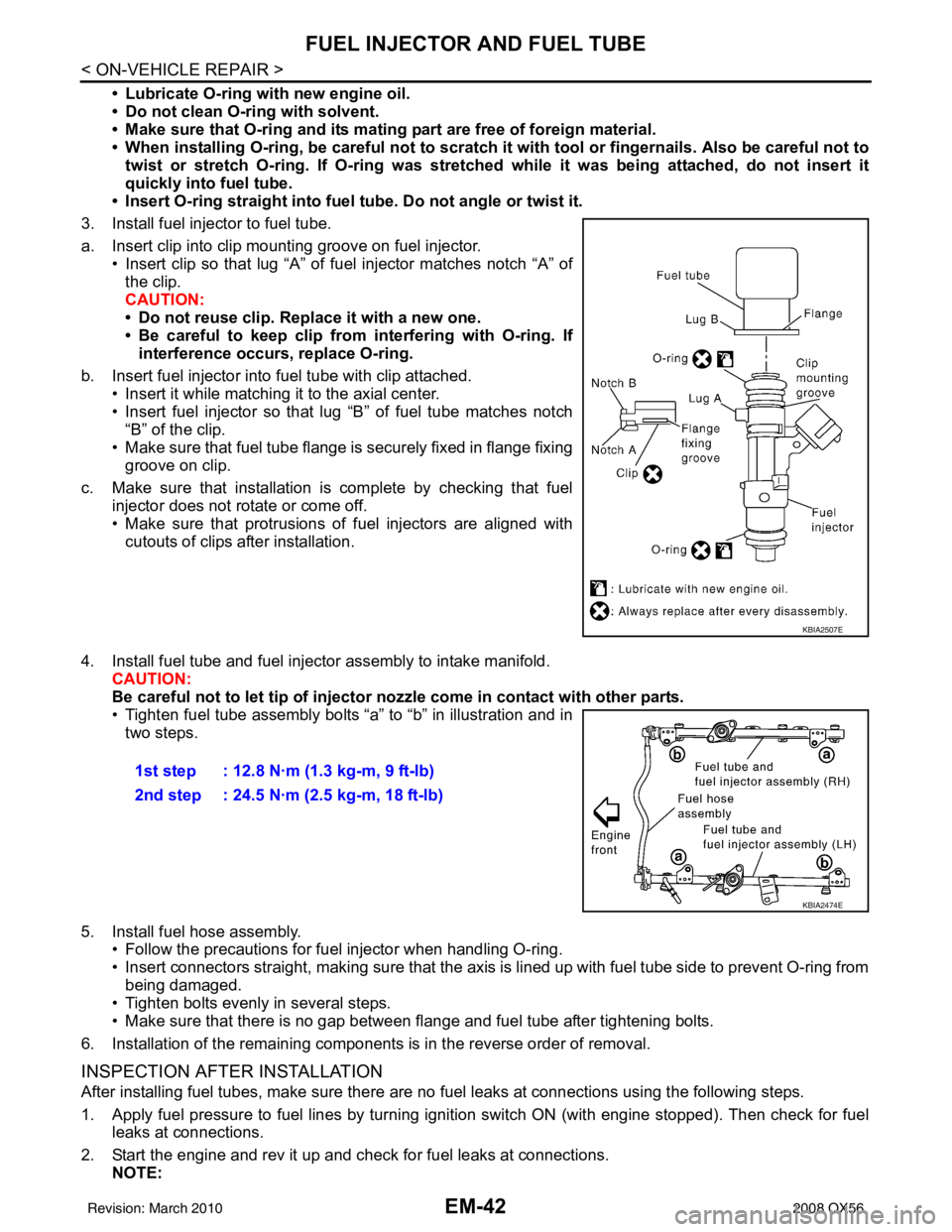
3. Install fuel injector to fuel tube.
a. Insert clip into clip mounting groove on fuel injector. • Insert clip so that lug “A” of fuel injector matches notch “A” ofthe clip.
CAUTION:
• Do not reuse clip. Replace it with a new one.
• Be careful to keep clip from interfering with O-ring. Ifinterference occurs, replace O-ring.
b. Insert fuel injector into fuel tube with clip attached. • Insert it while matching it to the axial center.
• Insert fuel injector so that lug “B” of fuel tube matches notch
“B” of the clip.
• Make sure that fuel tube flange is securely fixed in flange fixing groove on clip.
c. Make sure that installation is complete by checking that fuel injector does not rotate or come off.
• Make sure that protrusions of fuel injectors are aligned withcutouts of clips after installation.
4. Install fuel tube and fuel injector assembly to intake manifold. CAUTION:
Be careful not to let tip of injector nozzle come in contact with other parts.
• Tighten fuel tube assembly bolts “a” to “b” in illustration and in
two steps.
5. Install fuel hose assembly. • Follow the precautions for fuel injector when handling O-ring.
• Insert connectors straight, making sure that the axis is lined up with fuel tube side to prevent O-ring from
being damaged.
• Tighten bolts evenly in several steps.
• Make sure that there is no gap between flange and fuel tube after tightening bolts.
6. Installation of the remaining components is in the reverse order of removal.
INSPECTION AFTER INSTALLATION
After installing fuel tubes, make sure there are no fuel leaks at connections using the following steps.
1. Apply fuel pressure to fuel lines by turning ignition switch ON (with engine stopped). Then check for fuel leaks at connections.
2. Start the engine and rev it up and check for fuel leaks at connections. NOTE:
KBIA2507E
1st step : 12.8 N·m (1.3 kg-m, 9 ft-lb)
2nd step : 24.5 N·m (2.5 kg-m, 18 ft-lb)
KBIA2474E
Revision: March 2010 2008 QX56
Page 1846 of 4083
FUEL INJECTOR AND FUEL TUBEEM-43
< ON-VEHICLE REPAIR >
C
DE
F
G H
I
J
K L
M A
EM
NP
O
Use mirrors for checking on hidden points.
CAUTION:
Do not touch the engine imme
diately after stopping, as engine becomes extremely hot.
Revision: March 2010 2008 QX56