Page 3647 of 4083
TM-100
< COMPONENT DIAGNOSIS >
A/T SHIFT LOCK SYSTEM
Terminals And Reference Values
INFOID:0000000001604171
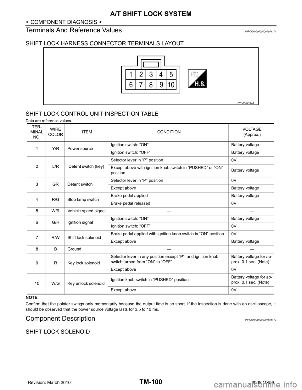
SHIFT LOCK HARNESS CONNECTOR TERMINALS LAYOUT
SHIFT LOCK CONTROL UNIT INSPECTION TABLE
Data are reference values.
NOTE:
Confirm that the pointer swings only momentarily because the output time is so short. If the inspection is done with an oscillo scope, it
should be observed that the power source voltage lasts for 3.5 to 10 ms.
Component DescriptionINFOID:0000000001604172
SHIFT LOCK SOLENOID
AWDIA0043ZZ
TER-
MINAL NO. WIRE
COLOR ITEM
CONDITION VOLTAGE
(Approx.)
1Y/RPower source Ignition switch: “ON”
Battery voltage
Ignition switch: “OFF” Battery voltage
2 L/R Detent switch (key) Selector lever in “P” position
0V
Except above with ignition knob switch in “PUSHED” or “ON”
position Battery voltage
3GRDetent switch Selector lever in “P” position
0V
Except above Battery voltage
4 R/G Stop lamp switch Brake pedal applied
Battery voltage
Brake pedal released 0V
5 W/R Vehicle speed signal ——
6 G/R Ignition signal Ignition switch: “ON”
Battery voltage
Ignition switch: “OFF” 0V
7 R/W Shift lock solenoid Brake pedal applied with ignition knob switch in “ON” position 0V
Except above
Battery voltage
8 B Ground ——
9 R Key lock solenoid Selector lever in any position except “P”, and ignition knob
switch turned from “ON” to “OFF”
Battery voltage for ap-
prox. 0.1 sec. (Note)
Except above 0V
10 W/G Key unlock solenoid Ignition knob switch in “PUSHED” position.
Battery voltage for ap-
prox. 0.1 sec. (Note)
Except above 0V
Revision: March 2010 2008 QX56
Page 3648 of 4083
A/T SHIFT LOCK SYSTEMTM-101
< COMPONENT DIAGNOSIS >
CEF
G H
I
J
K L
M A
B
TM
N
O P
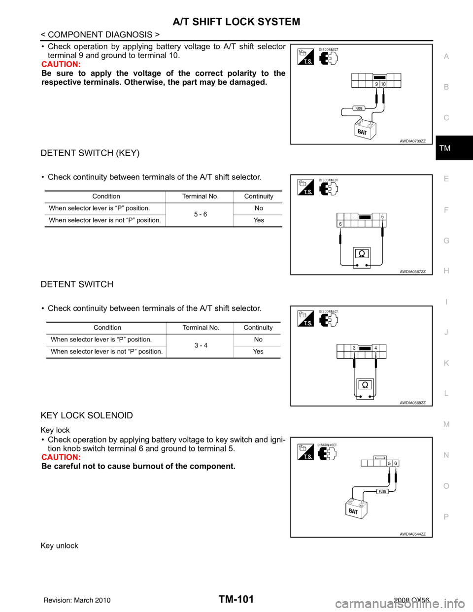
• Check operation by applying battery voltage to A/T shift selector terminal 9 and ground to terminal 10.
CAUTION:
Be sure to apply the voltage of the correct polarity to the
respective terminals. Otherwise, the part may be damaged.
DETENT SWITCH (KEY)
• Check continuity between terminals of the A/T shift selector.
DETENT SWITCH
• Check continuity between terminals of the A/T shift selector.
KEY LOCK SOLENOID
Key lock
• Check operation by applying battery voltage to key switch and igni-
tion knob switch terminal 6 and ground to terminal 5.
CAUTION:
Be careful not to cause burnout of the component.
Key unlock
AWDIA0700ZZ
Condition Terminal No. Continuity
When selector lever is “P” position. 5 - 6No
When selector lever is not “P” position. Yes
AWDIA0567ZZ
ConditionTerminal No. Continuity
When selector lever is “P” position. 3 - 4No
When selector lever is not “P” position. Yes
AWDIA0568ZZ
AWDIA0544ZZ
Revision: March 2010 2008 QX56
Page 3649 of 4083
TM-102
< COMPONENT DIAGNOSIS >
A/T SHIFT LOCK SYSTEM
• Check operation by applying battery voltage to key switch and igni-tion knob switch terminal 5 and ground to terminal 6.
CAUTION:
Be careful not to cause burnout of the component.
IGNITION KNOB SWITCH
• Check continuity between terminals of the key switch and ignition
knob switch.
STOP LAMP SWITCH
• Check continuity between stop lamp switch terminals 1 and 2.
Check stop lamp switch after adjusting brake pedal.
AWDIA0545ZZ
Condition Terminal No. Continuity
Switch pushed 1 - 2Ye s
Switch released No
AWDIA0546ZZ
ConditionTerminal No. Continuity
When brake pedal is depressed 1 -2Ye s
When brake pedal is released No
AWDIA0165ZZ
Revision: March 2010 2008 QX56
Page 3651 of 4083
TM-104
< ECU DIAGNOSIS >
TCM
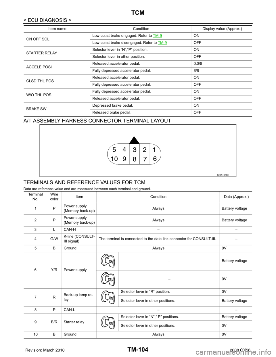
A/T ASSEMBLY HARNESS CONNECTOR TERMINAL LAYOUT
TERMINALS AND REFERENCE VALUES FOR TCM
Data are reference value and are measured between each terminal and ground.
ON OFF SOLLow coast brake engaged. Refer to
TM-9ON
Low coast brake disengaged. Refer to TM-9
OFF
STARTER RELAY Selector lever in “N”,“P” position.
ON
Selector lever in other position. OFF
ACCELE POSI Released accelerator pedal.
0.0/8
Fully depressed accelerator pedal. 8/8
CLSD THL POS Released accelerator pedal.
ON
Fully depressed accelerator pedal. OFF
W/O THL POS Fully depressed accelerator pedal.
ON
Released accelerator pedal. OFF
BRAKE SW Depressed brake pedal.
ON
Released brake pedal. OFF
Item name
Condition Display value (Approx.)
SCIA1658E
Te r m i n a l
No. Wire
color Item
ConditionData (Approx.)
1P Power supply
(Memory back-up)
Always
Battery voltage
2P Power supply
(Memory back-up) Always
Battery voltage
3 L CAN-H ––
4G/W K-line (CONSULT-
III signal) The terminal is connected to the data link connector for CONSULT-III.
–
5 B Ground Always0V
6Y/RPower supply –
Battery voltage
–0 V
7R Back-up lamp re-
lay Selector lever in “R” position.
0V
Selector lever in other positions. Battery voltage
8 P CAN-L ––
9 B/R Starter relay Selector lever in “N”,“ P”
positions. Battery voltage
Selector lever in other positions. 0V
10 B Ground Always0V
Revision: March 2010 2008 QX56
Page 3690 of 4083
SYSTEM SYMPTOMTM-143
< SYMPTOM DIAGNOSIS >
CEF
G H
I
J
K L
M A
B
TM
N
O P
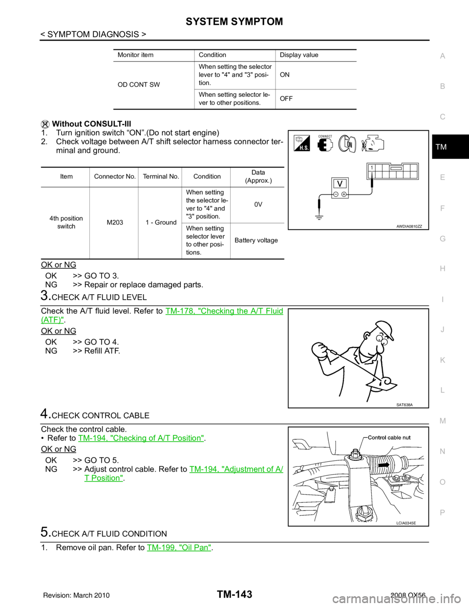
Without CONSULT-III
1. Turn ignition switch “ON”.(Do not start engine)
2. Check voltage between A/T shift selector harness connector ter- minal and ground.
OK or NG
OK >> GO TO 3.
NG >> Repair or replace damaged parts.
3.CHECK A/T FLUID LEVEL
Check the A/T fluid level. Refer to TM-178, "
Checking the A/T Fluid
(ATF)".
OK or NG
OK >> GO TO 4.
NG >> Refill ATF.
4.CHECK CONTROL CABLE
Check the control cable.
• Refer to TM-194, "
Checking of A/T Position".
OK or NG
OK >> GO TO 5.
NG >> Adjust control cable. Refer to TM-194, "
Adjustment of A/
T Position".
5.CHECK A/T FLUID CONDITION
1. Remove oil pan. Refer to TM-199, "
Oil Pan".
Monitor itemConditionDisplay value
OD CONT SW When setting the selector
lever to "4"
and "3" posi-
tion. ON
When setting selector le-
ver to other positions. OFF
Item Connector No. Terminal No. Condition Data
(Approx.)
4th position switch M203 1 - Ground When setting
the selector le-
ver to "4" and
"3" position.
0V
When setting
selector lever
to other posi-
tions. Battery voltage
AWDIA0810ZZ
SAT638A
LCIA0345E
Revision: March 2010
2008 QX56
Page 3695 of 4083
TM-148
< SYMPTOM DIAGNOSIS >
SYSTEM SYMPTOM
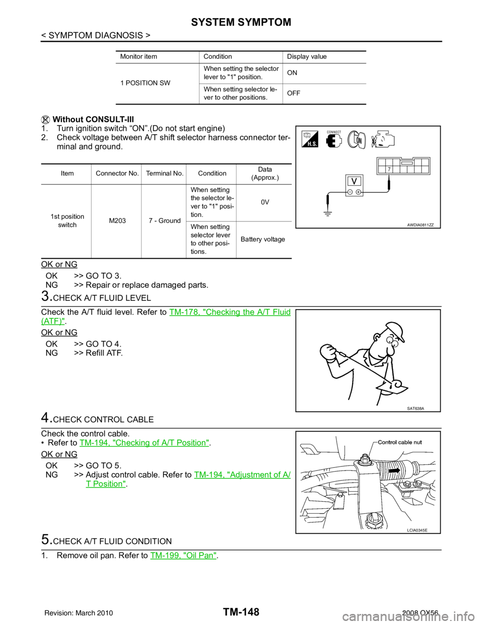
Without CONSULT-III
1. Turn ignition switch “ON”.(Do not start engine)
2. Check voltage between A/T shift selector harness connector ter-
minal and ground.
OK or NG
OK >> GO TO 3.
NG >> Repair or replace damaged parts.
3.CHECK A/T FLUID LEVEL
Check the A/T fluid level. Refer to TM-178, "
Checking the A/T Fluid
(ATF)".
OK or NG
OK >> GO TO 4.
NG >> Refill ATF.
4.CHECK CONTROL CABLE
Check the control cable.
• Refer to TM-194, "
Checking of A/T Position".
OK or NG
OK >> GO TO 5.
NG >> Adjust control cable. Refer to TM-194, "
Adjustment of A/
T Position".
5.CHECK A/T FLUID CONDITION
1. Remove oil pan. Refer to TM-199, "
Oil Pan".
Monitor itemConditionDisplay value
1 POSITION SW When setting the selector
lever to "1" position.
ON
When setting selector le-
ver to other positions. OFF
Item Connector No. Terminal No. Condition Data
(Approx.)
1st position switch M203 7 - Ground When setting
the selector le-
ver to "1" posi-
tion.
0V
When setting
selector lever
to other posi-
tions. Battery voltage
AWDIA0811ZZ
SAT638A
LCIA0345E
Revision: March 2010
2008 QX56
Page 3697 of 4083
TM-150
< SYMPTOM DIAGNOSIS >
SYSTEM SYMPTOM
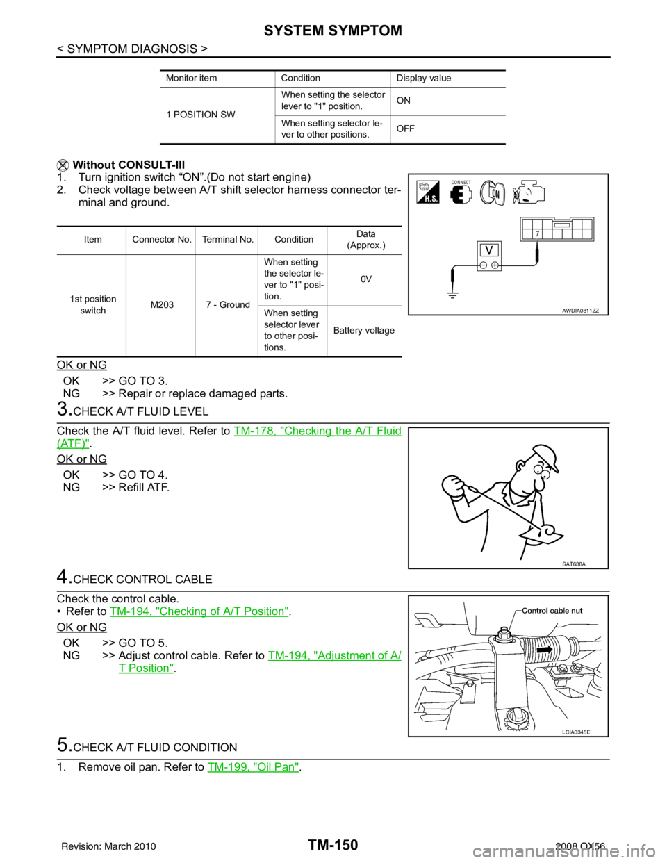
Without CONSULT-III
1. Turn ignition switch “ON”.(Do not start engine)
2. Check voltage between A/T shift selector harness connector ter-
minal and ground.
OK or NG
OK >> GO TO 3.
NG >> Repair or replace damaged parts.
3.CHECK A/T FLUID LEVEL
Check the A/T fluid level. Refer to TM-178, "
Checking the A/T Fluid
(ATF)".
OK or NG
OK >> GO TO 4.
NG >> Refill ATF.
4.CHECK CONTROL CABLE
Check the control cable.
• Refer to TM-194, "
Checking of A/T Position".
OK or NG
OK >> GO TO 5.
NG >> Adjust control cable. Refer to TM-194, "
Adjustment of A/
T Position".
5.CHECK A/T FLUID CONDITION
1. Remove oil pan. Refer to TM-199, "
Oil Pan".
Monitor itemConditionDisplay value
1 POSITION SW When setting the selector
lever to "1" position.
ON
When setting selector le-
ver to other positions. OFF
Item Connector No. Terminal No. Condition Data
(Approx.)
1st position switch M203 7 - Ground When setting
the selector le-
ver to "1" posi-
tion.
0V
When setting
selector lever
to other posi-
tions. Battery voltage
AWDIA0811ZZ
SAT638A
LCIA0345E
Revision: March 2010
2008 QX56
Page 3721 of 4083
TM-174
< PRECAUTION >
PRECAUTIONS
5. When the repair work is completed, return the ignition switch to the ″LOCK ″ position before connecting
the battery cables. (At this time, the steering lock mechanism will engage.)
6. Perform a self-diagnosis check of a ll control units using CONSULT-III.
Precaution for On Board Diagnosis (OBD) System of A/T and EngineINFOID:0000000001531485
The ECM has an on board diagnostic system. It will light up the malfunction indicator lamp (MIL) to warn the
driver of a malfunction causing emission deterioration.
CAUTION:
• Be sure to turn the ignition switch “OFF” and disconnect the negative battery cable before any repair
or inspection work. The open/short circuit of related switches, sensors, solenoid valves, etc. Will
cause the MIL to light up.
• Be sure to connect and lock the connectors secure ly after work. A loose (unlocked) connector will
cause the MIL to light up due to an open circuit. (Be sure the connector is free from water, grease,
dirt, bent terminals, etc.)
• Be sure to route and secure th e harnesses properly after work. Interference of the harness with a
bracket, etc. May cause the MIL to light up due to a short circuit.
• Be sure to connect rubber tubes properly afte r work. A misconnected or disconnected rubber tube
may cause the MIL to light up due to a malfunction of the EGR system or fuel injection system, etc.
• Be sure to erase the unnecessary malfunction informa tion (repairs completed) from the TCM and
ECM before returning the vehicle to the customer.
PrecautionINFOID:0000000001531486
NOTE:
If any malfunctions occur in the RE5R05A model tr ansmission, replace the entire transmission assem-
bly.
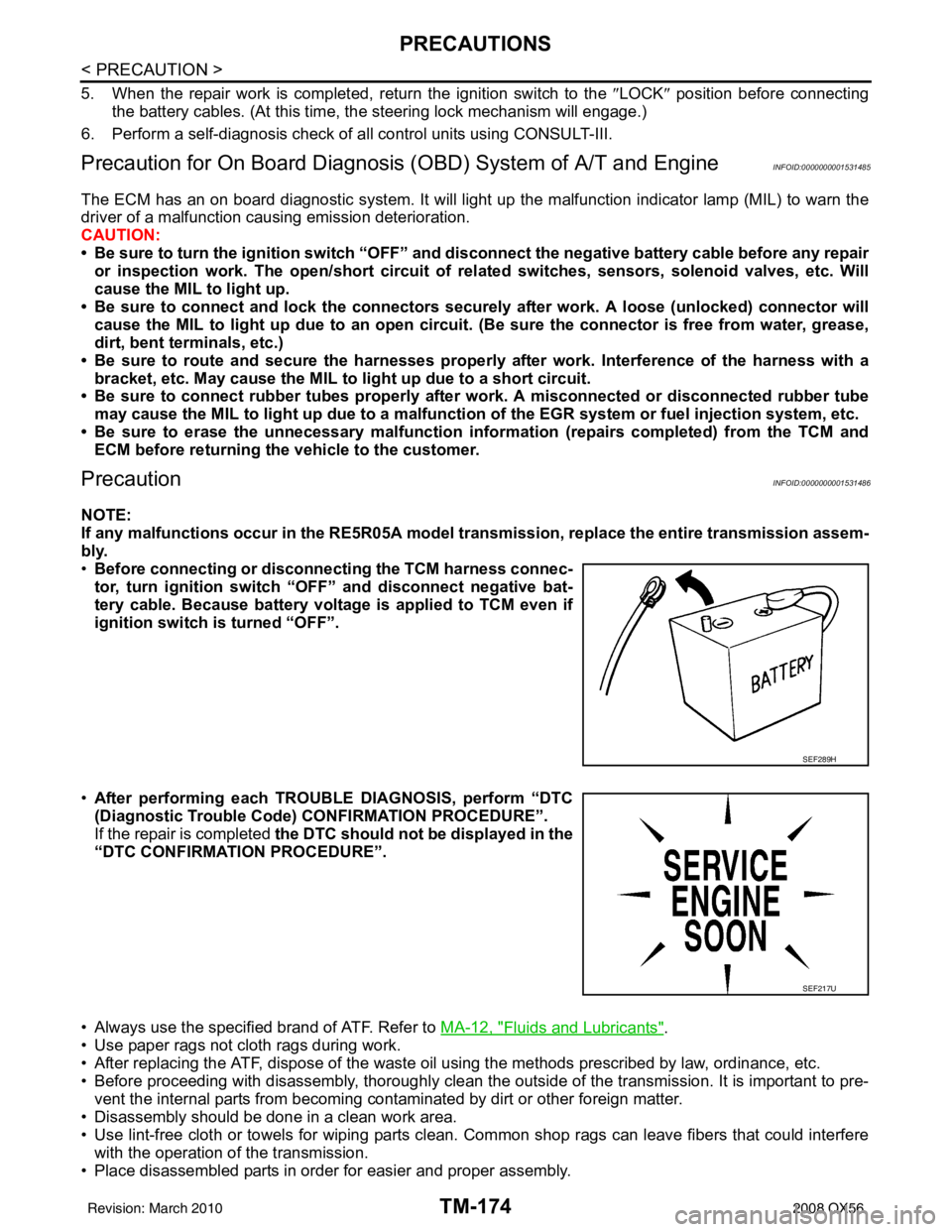
• Before connecting or disconn ecting the TCM harness connec-
tor, turn ignition switch “O FF” and disconnect negative bat-
tery cable. Because battery voltage is applied to TCM even if
ignition switch is turned “OFF”.
• After performing each TROUBLE DIAGNOSIS, perform “DTC
(Diagnostic Trouble Code) CONFIRMATION PROCEDURE”.
If the repair is completed the DTC should not be displayed in the
“DTC CONFIRMATION PROCEDURE”.
• Always use the specified brand of ATF. Refer to MA-12, "
Fluids and Lubricants".
• Use paper rags not cloth rags during work.
• After replacing the ATF, dispose of the waste oil using the methods prescribed by law, ordinance, etc.
• Before proceeding with disassembly, thoroughly clean the outside of the transmission. It is important to pre- vent the internal parts from becoming cont aminated by dirt or other foreign matter.
• Disassembly should be done in a clean work area.
• Use lint-free cloth or towels for wiping parts clean. Common shop rags can leave fibers that could interfere
with the operation of the transmission.
• Place disassembled parts in order for easier and proper assembly.
SEF289H
SEF217U
Revision: March 2010 2008 QX56