2008 INFINITI QX56 battery volt
[x] Cancel search: battery voltPage 3889 of 4083

WCS-12
< FUNCTION DIAGNOSIS >
DIAGNOSIS SYSTEM (METER)
DIAGNOSIS SYSTEM (METER)
Diagnosis DescriptionINFOID:0000000004872660
SELF-DIAGNOSIS MODE
The following items can be checked during Combination Meter Self-Diagnosis Mode.
• Gauge sweep and present gauge values.
• Illuminates all odometer/trip meters and A/T indicator segments.
• Illuminates all micro controlled lamps/LEDs regardless of switch position.
• Displays estimated present battery voltage.
• Displays seat belt buckle switch LH status.
OPERATION PROCEDURE
NOTE:
• Once entered, combination meter self-diagnosis mode will function with the ignition switch in ON or START.
Combination meter self-diagnosis mode will exit upon turning the ignition switch to OFF or ACC.
• If the diagnosis function is activated with trip A displa yed, the mileage on trip A is reset to 0000.0. (Trip B
operates the same way.)
To initiate combination meter self-diagnosis mode, refer to the following procedure.
1. Turn the ignition switch ON, while pressing the odometer/trip meter switch for 5 - 8 \
seconds. When the diagnosis function is activated, the odometer/trip meter will display tESt.
NOTE:
Check combination meter power supply and ground circuit when self-diagnosis mode of combination meter
does not start. Refer to MWI-30, "
COMBINATION METER : Diagnosis Procedure". Replace combination
meter if normal. Refer to MWI-76, "
Removal and Installation".
COMBINATION METER SELF-DIAGNOSIS MODE FUNCTIONS
To interpret combination meter self-diagnosis mode functions, refer to the following table.
EventOdometer Display Description of Test/Data Notes:
Odometer/trip meter A/B
switch held from 5 to 8
seconds (or until re-
leased) tESt
Initiating self-diagnosis mode
Switch released GAGE Performs sweep of all
gauges, then displays
present gauge values.Gauges sweep within 10 seconds
Switch pressed (All segments illuminated) Lights all LCD segments.
Compare with picture.
Switch pressed bulbIlluminates all micro-con-
trolled lamps/LEDs. Part may not be configured for all
lamps (functions) th
at turn on dur-
ing test. This is normal.
Switch pressed r XXXX, FAIL Return to normal opera-
tion of all lamps/LEDs and
displays “r XXXX”.If a malfunction exists, “FAIL” will
flash.
Switch pressed nrXXXX Displays Hex ROM rev as
stored in NVM.
Switch pressed EE XX, FAIL Displays “EE XX”.If a malfunction exists, “FAIL” will
flash.
Switch pressed dtXXXX Hex coding of final manu-
facturing test date.
AWNIA0203ZZ
Revision: March 2010
2008 QX56
Page 3890 of 4083

WCS
DIAGNOSIS SYSTEM (METER)WCS-13
< FUNCTION DIAGNOSIS >
C
DE
F
G H
I
J
K L
M B A
O P
CONSULT-III Function (METER/M&A)INFOID:0000000004872661
CONSULT-III can display each diagnostic item us ing the diagnostic test modes shown following.
SELF-DIAG RESULTS
Display Item List
Refer to MWI-62, "DTC Index".
DATA MONITOR
Display Item List
Switch pressed
(3 times) Sc1 XX through Epr XXDisplays 8 bit software
configuration value in Hex
format
Switch pressed 1nF XXDisplays 8-bit market info
value in Hex format. $31 = USA
$2A = Canada
Switch pressed
(3 times) cYL XX through tF N/A
Switch pressed XXXXX “Corrected” speed value
in hundredths of MPH.
Gauge indication may be
slightly higher. This is nor-
mal.Will display “-----” if message is not
received. Will display “99999” if
data received is invalid.
Switch pressed XXXXX “Corrected” speed value
in hundredths of KPH.
Gauge indication may be
slightly different. This is
normal.Will display “-----” if message is not
received. Will display “99999” if
data received is invalid.
Switch pressed t XXXX Tachometer value in
RPM. Gauge indication
may be higher at higher
RPM. This is normal.Will display “-----” if message is not
received.
Switch pressed F1XXXX Present fuel level A/D in-
put. This input represents
fuel sender input.000-009 = Short circuit
010-254 = Normal range
255 = Open circuit
Switch pressed F2XXX Present FLPS.010-254 = Normal range
Switch pressed XXXC Last temperature gauge
input value in degrees C.
Temperature gauge indi-
cates present tempera-
ture per indication
standard.Will display “---”C if
message is not
received.
Will display “999” if data received
is invalid.
High = 130 deg C
Normal = 70 - 105 deg C
Low = less than 50 deg C
Switch pressed BAtXX.X Estimated present battery
voltage.
Switch pressed rES -X Seat belt buckle switch LH
status.1= Buckled
0 = Unbuckled
Switch pressed
(32 times) PA -XX through PA1-XX N/A
Switch pressed GAGE Return to beginning of self-diagno-
sis cycle.
Event
Odometer Display Description of Test/Data Notes:
METER/M&A diagnosis mode Description
SELF-DIAG RESULTS Displays combination meter self-diagnosis results. DATA MONITOR Displays combination meter input/output data in real time.
CAN DIAG SUPPORT MNTR The result of transmit/receive diagnosis of CAN communication can be read.
Revision: March 2010 2008 QX56
Page 3894 of 4083
WCS
POWER SUPPLY AND GROUND CIRCUITWCS-17
< COMPONENT DIAGNOSIS >
C
DE
F
G H
I
J
K L
M B A
O P
COMPONENT DIAGNOSIS
POWER SUPPLY AND GROUND CIRCUIT
COMBINATION METER
COMBINATION METER : Diagnosis ProcedureINFOID:0000000004873060
1.CHECK FUSES
Check for blown combination meter fuses.
Is the inspection result normal?
YES >> GO TO 2
NO >> If fuse is blown, be sure to eliminate cause of malfunction before installing new fuse.
2.POWER SUPPLY CIRCUIT CHECK
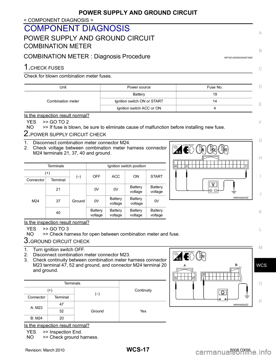
1. Disconnect combination meter connector M24.
2. Check voltage between combination meter harness connector M24 terminals 21, 37, 40 and ground.
Is the inspection result normal?
YES >> GO TO 3
NO >> Check harness for open between combination meter and fuse.
3.GROUND CIRCUIT CHECK
1. Turn ignition switch OFF.
2. Disconnect combination meter connector M23.
3. Check continuity between combination meter harness connector M23 terminal 47, 52 and ground, and connector M24 terminal 20
and ground.
Is the inspection result normal?
YES >> Inspection End.
NO >> Check ground harness.
Unit Power source Fuse No.
Combination meter Battery 19
Ignition switch ON or START 14
Ignition switch ACC or ON 4
TerminalsIgnition switch position
(+) (–) OFF ACC ON START
Connector Terminal
M24 21
Ground 0V 0V
Battery
voltage Battery
voltage
37 0VBattery
voltage Battery
voltage 0V
40 Battery
voltage Battery
voltage Battery
voltage Battery
voltage
AWNIA0204ZZ
Te r m i n a l s
Continuity
(+)
(–)
Connector Terminal
A: M23 47
Ground Yes
52
B: M24 20
AWNIA0205ZZ
Revision: March 2010 2008 QX56
Page 3895 of 4083
WCS-18
< COMPONENT DIAGNOSIS >
POWER SUPPLY AND GROUND CIRCUIT
BCM (BODY CONTROL MODULE)
BCM (BODY CONTROL MODULE) : Diagnosis ProcedureINFOID:0000000004873061
1. CHECK FUSES AND FUSIBLE LINK
Check that the following fuses and fusible link are not blown.
Is the fuse blown?
YES >> Replace the blown fuse or fusible link after repairing the affected circuit.
NO >> GO TO 2
2. CHECK POWER SUPPLY CIRCUIT
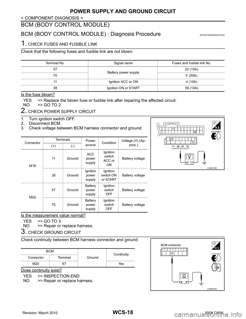
1. Turn ignition switch OFF.
2. Disconnect BCM.
3. Check voltage between BCM harness connector and ground.
Is the measurement value normal?
YES >> GO TO 3
NO >> Repair or replace harness.
3. CHECK GROUND CIRCUIT
Check continuity between BCM harness connector and ground.
Does continuity exist?
YES >> INSPECTION END
NO >> Repair or replace harness.
Terminal No. Signal nameFuses and fusible link No.
57 Battery power supply 22 (15A)
70 F (50A)
11 Ignition ACC or ON 4 (10A)
38 Ignition ON or START 59 (10A)
ConnectorTe r m i n a l s
Power
source Condition
Voltage (V) (Ap-
prox.)
(+) (-)
M18 11 Ground
ACC
power
supply Ignition
switch
ACC or ON Battery voltage
38 Ground Ignition
power
supply Ignition
switch ON or START Battery voltage
M20 57 Ground
Battery
power
supply Ignition
switch
OFF Battery voltage
70 Ground Battery
power
supply Ignition
switch OFF Battery voltage
LIIA2415E
BCM
GroundContinuity
Connector Terminal
M20 67 Yes
LIIA0915E
Revision: March 2010 2008 QX56
Page 3899 of 4083
WCS-22
< COMPONENT DIAGNOSIS >
KEY SWITCH SIGNAL CIRCUIT
KEY SWITCH SIGNAL CIRCUIT
DescriptionINFOID:0000000001697685
Transmits a key switch signal to the BCM.
Component Function CheckINFOID:0000000001697686
1.CHECK BCM INPUT SIGNAL
Select “DATA MONITOR” for “BCM” and check the “KEY ON SW” monitor value.
>> Inspection End.
Diagnosis ProcedureINFOID:0000000001697687
1.CHECK FUSE
Check if the key switch and ignition knob switch 10A fuse (No. 62, located in the fuse and relay box) is blown.
Is the fuse blown?
YES >> Be sure to repair the cause of malfunction before installing new fuse.
NO >> GO TO 2
2.CHECK BCM INPUT SIGNAL
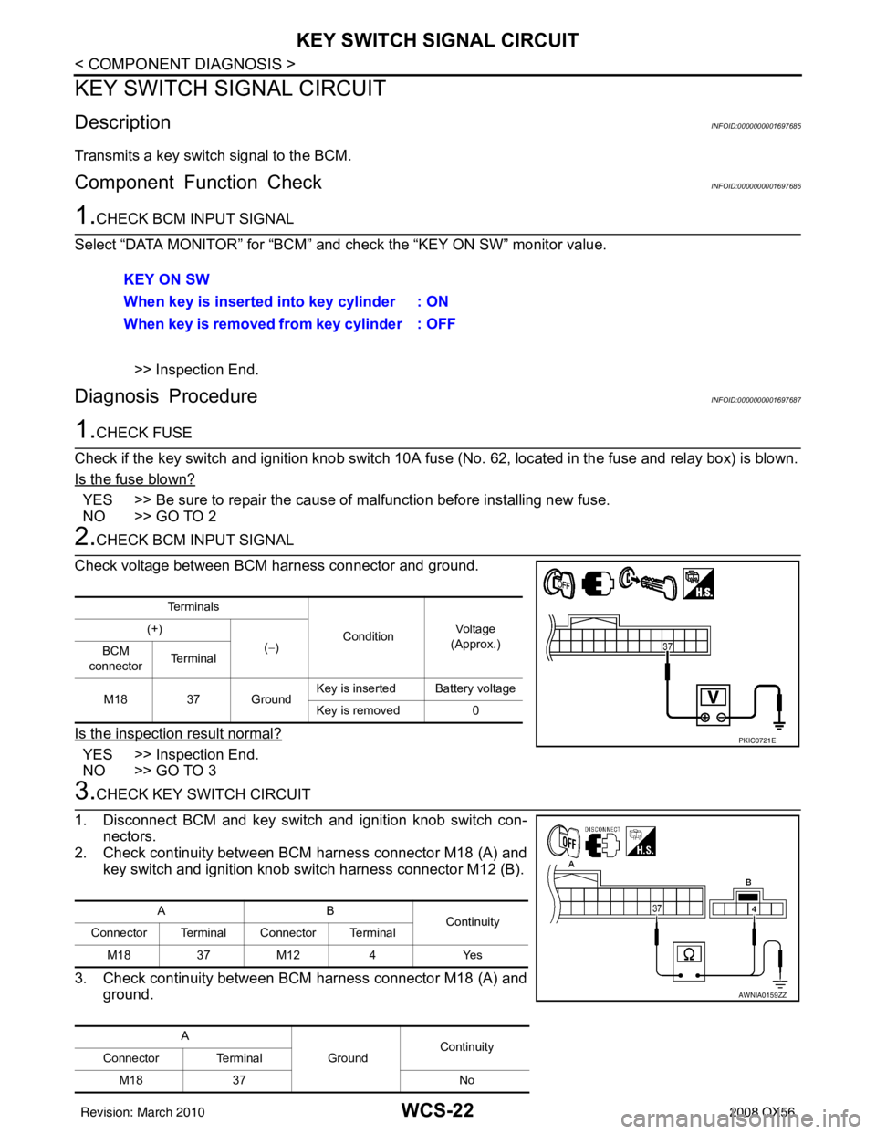
Check voltage between BCM harness connector and ground.
Is the inspection result normal?
YES >> Inspection End.
NO >> GO TO 3
3.CHECK KEY SWITCH CIRCUIT
1. Disconnect BCM and key switch and ignition knob switch con- nectors.
2. Check continuity between BCM harness connector M18 (A) and key switch and ignition knob switch harness connector M12 (B).
3. Check continuity between BCM harness connector M18 (A) and ground.KEY ON SW
When key is inserted into key cylinder : ON
When key is removed from key cylinder : OFF
Te r m i n a l s
ConditionVo l ta g e
(Approx.)
(+)
(−)
BCM
connector Te r m i n a l
M18 37 Ground Key is inserted Battery voltage
Key is removed
0
PKIC0721E
AB
Continuity
Connector Terminal Connector Terminal
M183 7M 12 4 Y es
A GroundContinuity
Connector Terminal
M18 37 No
AWNIA0159ZZ
Revision: March 2010 2008 QX56
Page 3900 of 4083
WCS
KEY SWITCH SIGNAL CIRCUITWCS-23
< COMPONENT DIAGNOSIS >
C
DE
F
G H
I
J
K L
M B A
O P
Is the inspection result normal?
YES >> GO TO 4
NO >> Repair harness or connector.
4.CHECK KEY SWITCH POWER SUPPLY CIRCUIT
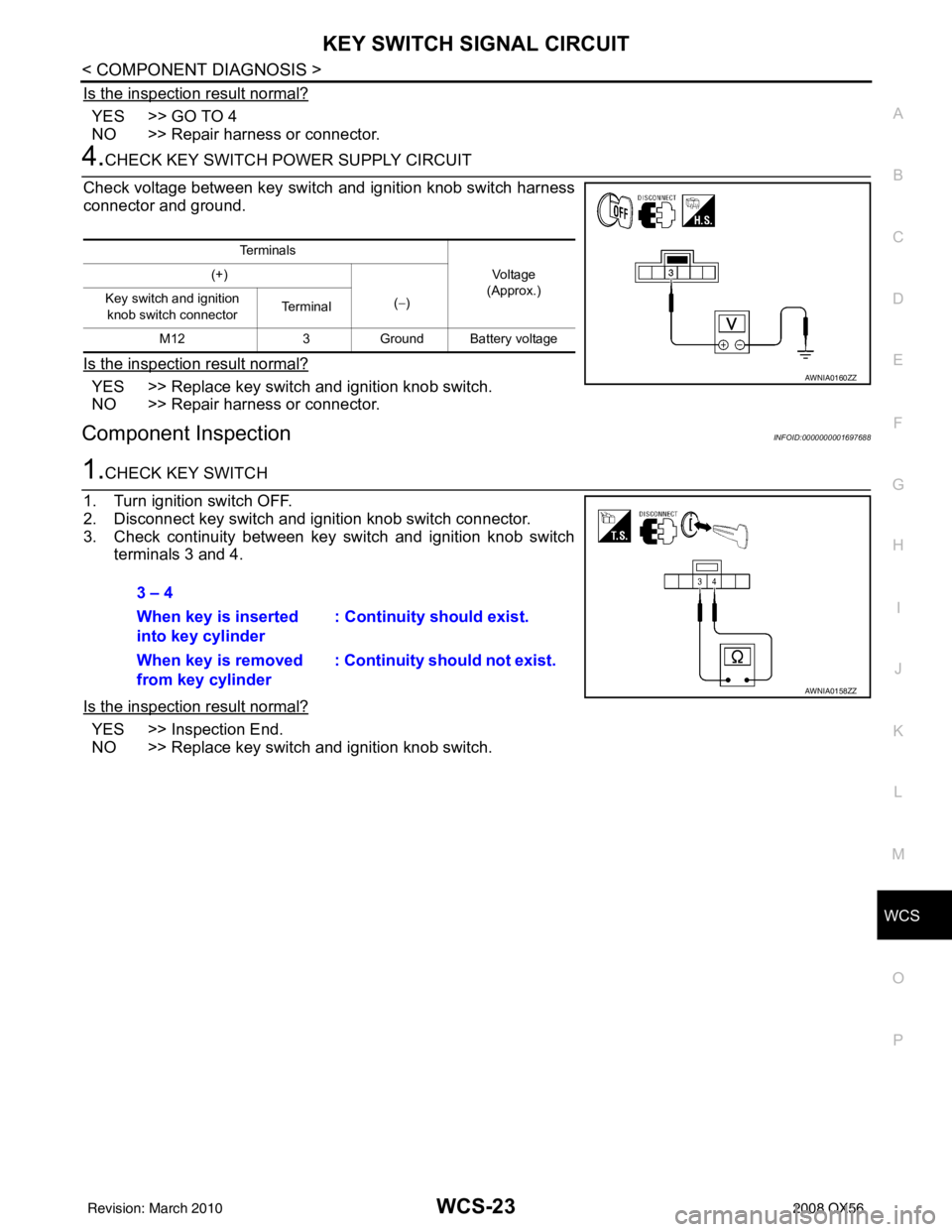
Check voltage between key switch and ignition knob switch harness
connector and ground.
Is the inspection result normal?
YES >> Replace key switch and ignition knob switch.
NO >> Repair harness or connector.
Component InspectionINFOID:0000000001697688
1.CHECK KEY SWITCH
1. Turn ignition switch OFF.
2. Disconnect key switch and i gnition knob switch connector.
3. Check continuity between key switch and ignition knob switch terminals 3 and 4.
Is the inspection result normal?
YES >> Inspection End.
NO >> Replace key switch and ignition knob switch.
Te r m i n a l s Vo l ta g e
(Approx.)
(+)
(−)
Key switch and ignition
knob switch connector Te r m i n a l
M12 3Ground Battery voltage
AWNIA0160ZZ
3 – 4
When key is inserted
into key cylinder : Continuity should exist.
When key is removed
from key cylinder : Continuity should not exist.
AWNIA0158ZZ
Revision: March 2010
2008 QX56
Page 3906 of 4083
WCS
COMBINATION METERWCS-29
< ECU DIAGNOSIS >
C
DE
F
G H
I
J
K L
M B A
O P
ECU DIAGNOSIS
COMBINATION METER
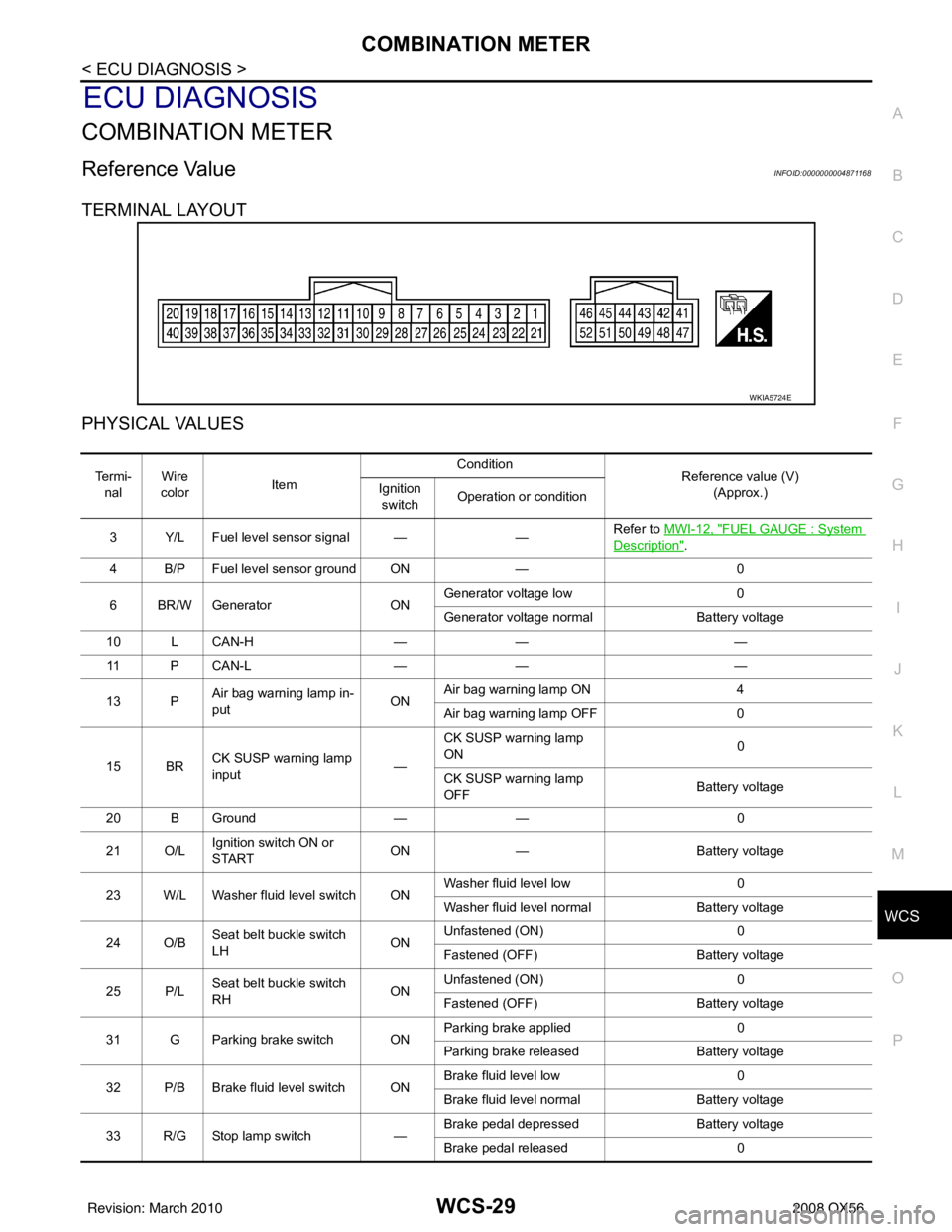
Reference ValueINFOID:0000000004871168
TERMINAL LAYOUT
PHYSICAL VALUES
WKIA5724E
Te r m i - nal Wire
color Item Condition
Reference value (V)
(Approx.)
Ignition
switch Operation or condition
3 Y/L Fuel level sensor signal — —Refer to
MWI-12, "
FUEL GAUGE : System
Description".
4 B/P Fuel level sensor ground ON —0
6 BR/W Generator ONGenerator voltage low
0
Generator voltage normal Battery voltage
10 L CAN-H —— —
11 P C A N - L —— —
13 P Air bag warning lamp in-
put ONAir bag warning lamp ON
4
Air bag warning lamp OFF 0
15 BR CK SUSP warning lamp
input —CK SUSP warning lamp
ON
0
CK SUSP warning lamp
OFF Battery voltage
20 B Ground —— 0
21 O/L Ignition switch ON or
START ON
— Battery voltage
23 W/L Washer fluid level switch ON Washer fluid level low
0
Washer fluid level normal Battery voltage
24 O/B Seat belt buckle switch
LH ONUnfastened (ON)
0
Fastened (OFF) Battery voltage
25 P/L Seat belt buckle switch
RH ONUnfastened (ON)
0
Fastened (OFF) Battery voltage
31 G Parking brake switch ON Parking brake applied
0
Parking brake released Battery voltage
32 P/B Brake fluid level switch ON Brake fluid level low
0
Brake fluid level normal Battery voltage
33 R/G Stop lamp switch —Brake pedal depressed
Battery voltage
Brake pedal released 0
Revision: March 2010 2008 QX56
Page 3907 of 4083
WCS-30
< ECU DIAGNOSIS >
COMBINATION METER
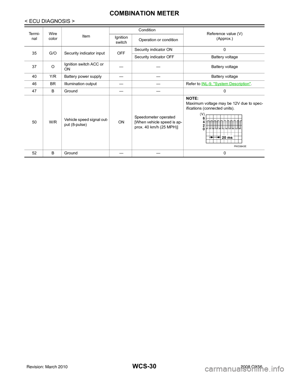
35 G/O Security indicator input OFFSecurity indicator ON 0
Security indicator OFF
Battery voltage
37 O Ignition switch ACC or
ON
—
— Battery voltage
40 Y/R Battery power supply — —Battery voltage
46 BR Illumination output ——Refer to INL-9, "
System Description".
47 B Ground —— 0
50 W/R Vehicle speed signal out-
put (8-pulse) ONSpeedometer operated
[When vehicle speed is ap-
prox. 40 km/h (25 MPH)] NOTE:
Maximum voltage may be 12V due to spec-
ifications (connected units).
52 B Ground —— 0
Te r m i -
nal Wire
color Item Condition
Reference value (V)
(Approx.)
Ignition
switch Operation or condition
PKIC0643E
Revision: March 2010
2008 QX56