2008 INFINITI QX56 battery volt
[x] Cancel search: battery voltPage 3338 of 4083
SN
POWER SUPPLY AND GROUND CIRCUITSN-13
< COMPONENT DIAGNOSIS >
C
DE
F
G H
I
J
K L
M B A
O P
COMPONENT DIAGNOSIS
POWER SUPPLY AND GROUND CIRCUIT
Diagnosis Procedure Fo r Rear Sonar SystemINFOID:0000000001754066
INSPECTION FOR POWER SUPPLY AND GROUND CIRCUIT
1.CHECK FUSES
Check for blown rear sonar system fuses.
Are any fuses blown?
YES >> If fuse is blown, be sure to eliminate cause of malfunction before installing new fuse. Refer to GI-
41, "Circuit Inspection".
NO >> GO TO 2.
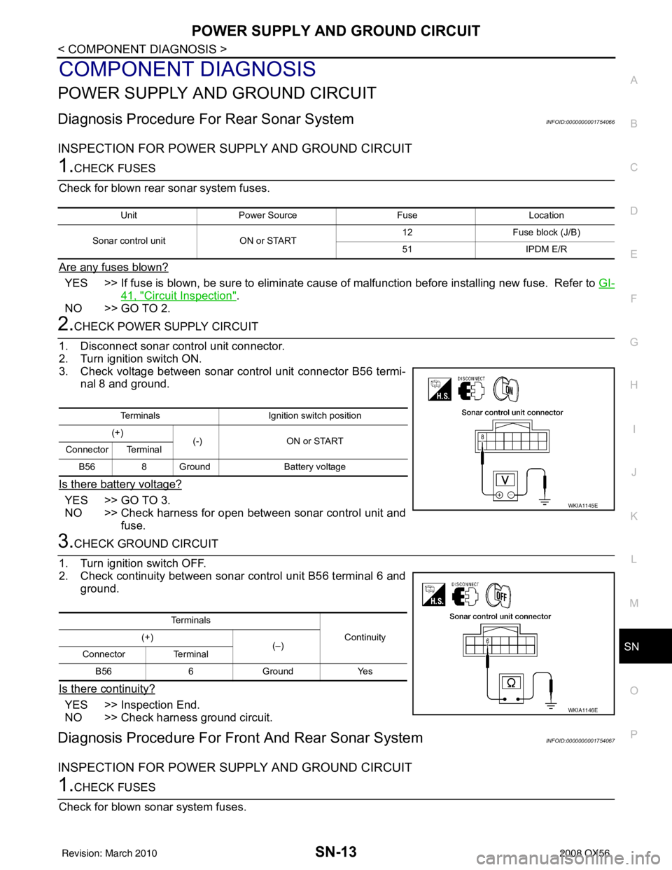
2.CHECK POWER SUPPLY CIRCUIT
1. Disconnect sonar control unit connector.
2. Turn ignition switch ON.
3. Check voltage between sonar control unit connector B56 termi- nal 8 and ground.
Is there battery voltage?
YES >> GO TO 3.
NO >> Check harness for open between sonar control unit and fuse.
3.CHECK GROUND CIRCUIT
1. Turn ignition switch OFF.
2. Check continuity between sonar control unit B56 terminal 6 and ground.
Is there continuity?
YES >> Inspection End.
NO >> Check harness ground circuit.
Diagnosis Procedure For Fron t And Rear Sonar SystemINFOID:0000000001754067
INSPECTION FOR POWER SUPPLY AND GROUND CIRCUIT
1.CHECK FUSES
Check for blown sonar system fuses.
Unit Power Source FuseLocation
Sonar control unit ON or START 12
Fuse block (J/B)
51 IPDM E/R
Terminals Ignition switch position
(+) (-) ON or START
Connector Terminal
B56 8 Ground Battery voltage
WKIA1145E
Te r m i n a l s
Continuity
(+)
(–)
Connector Terminal
B56 6 Ground Yes
WKIA1146E
Revision: March 2010 2008 QX56
Page 3339 of 4083
SN-14
< COMPONENT DIAGNOSIS >
POWER SUPPLY AND GROUND CIRCUIT
Are any fuses blown?
YES >> If fuse is blown, be sure to eliminate cause of malfunction before installing new fuse. Refer to GI-
41, "Circuit Inspection".
NO >> GO TO 2.
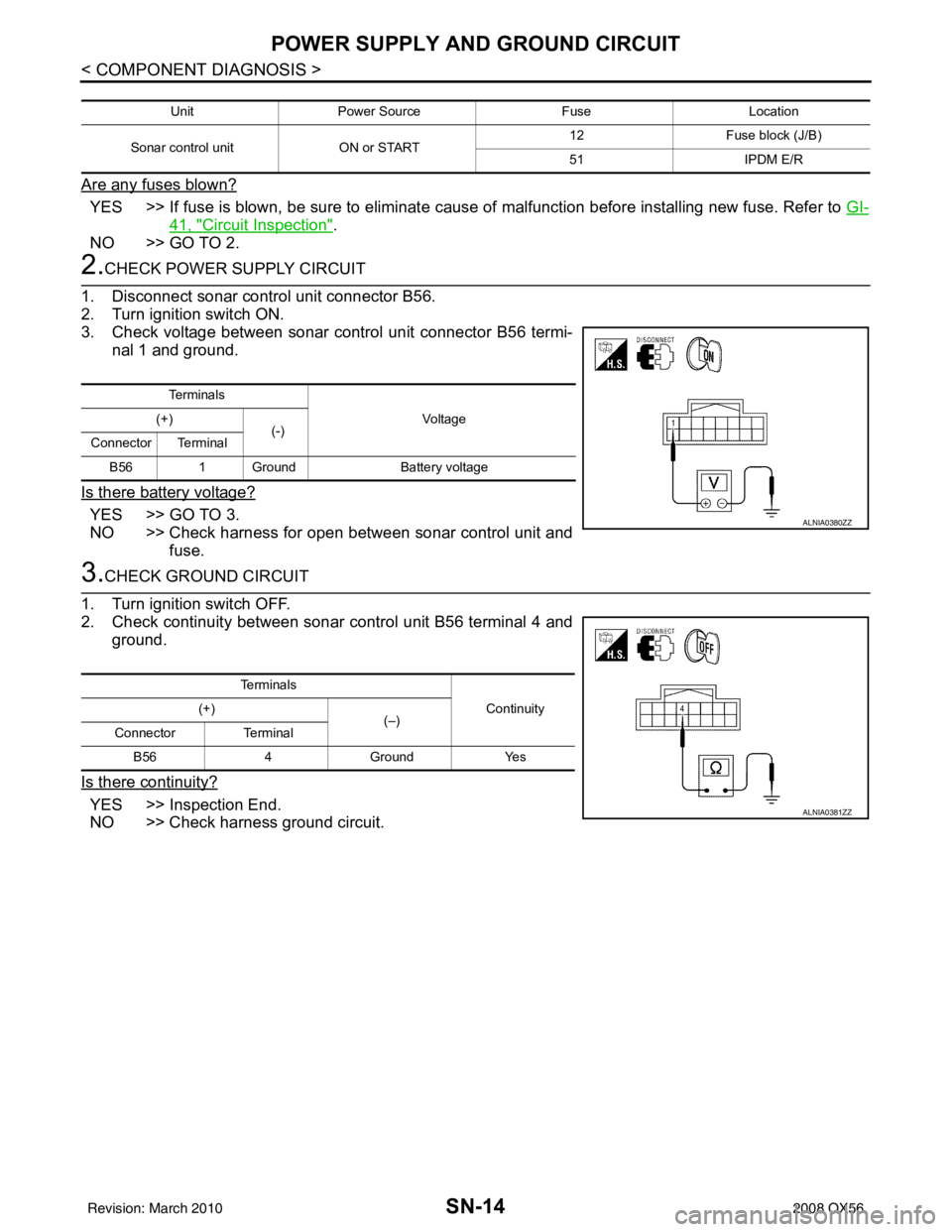
2.CHECK POWER SUPPLY CIRCUIT
1. Disconnect sonar control unit connector B56.
2. Turn ignition switch ON.
3. Check voltage between sonar control unit connector B56 termi- nal 1 and ground.
Is there battery voltage?
YES >> GO TO 3.
NO >> Check harness for open between sonar control unit and fuse.
3.CHECK GROUND CIRCUIT
1. Turn ignition switch OFF.
2. Check continuity between sonar control unit B56 terminal 4 and ground.
Is there continuity?
YES >> Inspection End.
NO >> Check harness ground circuit.
Unit Power Source FuseLocation
Sonar control unit ON or START 12
Fuse block (J/B)
51 IPDM E/R
Te r m i n a l s
Vo l ta g e
(+)
(-)
Connector Terminal
B56 1 Ground Battery voltage
ALNIA0380ZZ
Te r m i n a l s
Continuity
(+)
(–)
Connector Terminal
B56 4Ground Yes
ALNIA0381ZZ
Revision: March 2010 2008 QX56
Page 3345 of 4083
SN-20
< COMPONENT DIAGNOSIS >
SONAR SYSTEM OFF SWITCH CIRCUIT INSPECTION
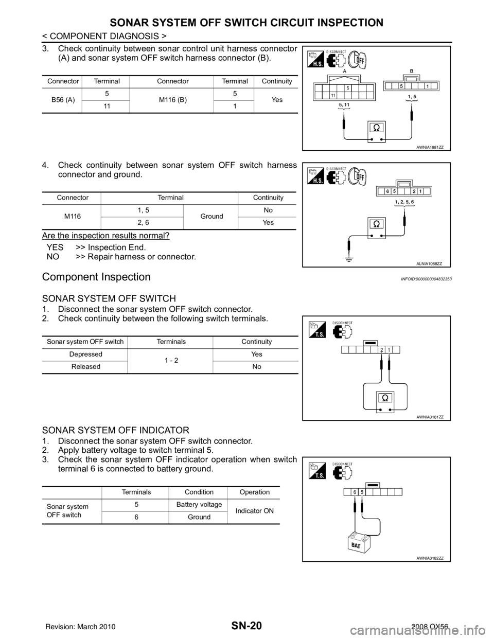
3. Check continuity between sonar control unit harness connector(A) and sonar system OFF switch harness connector (B).
4. Check continuity between sonar system OFF switch harness connector and ground.
Are the inspection results normal?
YES >> Inspection End.
NO >> Repair harness or connector.
Component InspectionINFOID:0000000004832353
SONAR SYSTEM OFF SWITCH
1. Disconnect the sonar system OFF switch connector.
2. Check continuity between the following switch terminals.
SONAR SYSTEM OFF INDICATOR
1. Disconnect the sonar system OFF switch connector.
2. Apply battery voltage to switch terminal 5.
3. Check the sonar system OFF indicator operation when switch terminal 6 is connected to battery ground.
Connector Terminal Connector Terminal Continuity
B56 (A) 5
M116 (B) 5
Ye s
11 1
AWNIA1881ZZ
ConnectorTerminalContinuity
M116 1, 5
Ground No
2, 6 Yes
ALNIA1088ZZ
Sonar system OFF switch Terminals Continuity
Depressed 1 - 2Ye s
Released No
AWNIA0181ZZ
Terminals Condition Operation
Sonar system
OFF switch 5
Battery voltage
Indicator ON
6G ro u nd
AWNIA0182ZZ
Revision: March 2010 2008 QX56
Page 3346 of 4083
SN
SONAR CONTROL UNIT FOR REAR SONAR SYSTEMSN-21
< ECU DIAGNOSIS >
C
DE
F
G H
I
J
K L
M B A
O P
ECU DIAGNOSIS
SONAR CONTROL UNIT FO R REAR SONAR SYSTEM
Reference ValueINFOID:0000000001754070
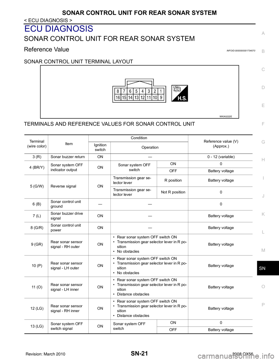
SONAR CONTROL UNIT TERMINAL LAYOUT
TERMINALS AND REFERENCE VA LUES FOR SONAR CONTROL UNIT
WKIA5222E
Te r m i n a l
(wire color) Item Condition
Reference value (V)
(Approx.)
Ignition
switch Operation
3 (R) Sonar buzzer return ON —0 - 12 (variable)
4 (BR/Y) Sonar system OFF
indicator output ON
Sonar system OFF
switch ON
0
OFF Battery voltage
5 (G/W) Reverse signal ONTransmission gear se-
lector lever
R position
Battery voltage
Transmission gear se-
lector lever Not R position
0
6 (B) Sonar control unit
ground ——
0
7 (L) Sonar buzzer drive
signal
ON
— Battery voltage
8 (G/R) Sonar control unit
power ON
— Battery voltage
9 (GR) Rear sonar sensor
signal - RH outer
ON• Rear sonar system OFF switch ON
• Transmission gear selector lever in R po-
sition
• No obstacles Battery voltage
10 (P) Rear sonar sensor
signal - LH outer
ON• Rear sonar system OFF switch ON
• Transmission gear selector lever in R po-
sition
• No obstacles Battery voltage
11 ( O ) Rear sonar sensor
signal - LH inner
ON• Rear sonar system OFF switch ON
• Transmission gear selector lever in R po-
sition
• Distance obstacles Battery voltage
12 (LG) Rear sonar sensor
signal - RH inner
ON• Rear sonar system OFF switch ON
• Transmission gear selector lever in R po-
sition
• Distance obstacles Battery voltage
13 (LG) Sonar system OFF
switch signal
ONSonar system OFF
switch ON
0
OFF Battery voltage
Revision: March 2010 2008 QX56
Page 3347 of 4083

SN-22
< ECU DIAGNOSIS >
SONAR CONTROL UNIT FOR REAR SONAR SYSTEM
15 (Y)Rear sonar sensor
ground
ON
— 0
16 (LG/B) Rear sonar sensor
power ON Ignition switch ON
Battery voltage
Te r m i n a l
(wire color) Item Condition
Reference value (V)
(Approx.)
Ignition
switch Operation
Revision: March 2010
2008 QX56
Page 3356 of 4083
SN
SONAR CONTROL UNIT FOR FRONT AND REAR SONAR SYSTEMSN-31
< ECU DIAGNOSIS >
C
DE
F
G H
I
J
K L
M B A
O P
SONAR CONTROL UNIT FOR FR ONT AND REAR SONAR SYSTEM
Reference ValueINFOID:0000000001754073
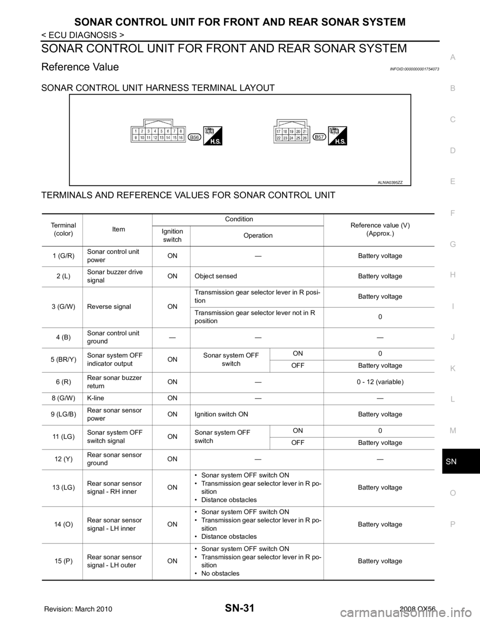
SONAR CONTROL UNIT HARNESS TERMINAL LAYOUT
TERMINALS AND REFERENCE VA LUES FOR SONAR CONTROL UNIT
ALNIA0395ZZ
Te r m i n a l
(color) Item Condition
Reference value (V)
(Approx.)
Ignition
switch Operation
1 (G/R) Sonar control unit
power ON
— Battery voltage
2 (L) Sonar buzzer drive
signal
ON Object sensed
Battery voltage
3 (G/W) Reverse signal ONTransmission gear selector lever in R posi-
tion
Battery voltage
Transmission gear selector lever not in R
position 0
4 (B) Sonar control unit
ground ——
—
5 (BR/Y) Sonar system OFF
indicator output ON
Sonar system OFF
switch ON
0
OFF Battery voltage
6 (R) Rear sonar buzzer
return
ON
— 0 - 12 (variable)
8 (G/W) K-line ON— —
9 (LG/B) Rear sonar sensor
power ON Ignition switch ON
Battery voltage
11 ( L G ) Sonar system OFF
switch signal
ONSonar system OFF
switch ON
0
OFF Battery voltage
12 (Y) Rear sonar sensor
ground ON
— —
13 (LG) Rear sonar sensor
signal - RH inner ON• Sonar system OFF switch ON
• Transmission gear selector lever in R po-
sition
• Distance obstacles Battery voltage
14 (O) Rear sonar sensor
signal - LH inner ON• Sonar system OFF switch ON
• Transmission gear selector lever in R po-
sition
• Distance obstacles Battery voltage
15 (P) Rear sonar sensor
signal - LH outer ON• Sonar system OFF switch ON
• Transmission gear selector lever in R po-
sition
• No obstacles Battery voltage
Revision: March 2010
2008 QX56
Page 3357 of 4083
SN-32
< ECU DIAGNOSIS >
SONAR CONTROL UNIT FOR FRONT AND REAR SONAR SYSTEM
16 (GR)Rear sonar sensor
signal - RH outer ON• Sonar system OFF switch ON
• Transmission gear selector lever in R po-
sition
• No obstacles Battery voltage
17 (LG/B) Front sonar sensor
power
ON Ignition switch ON
Battery voltage
18 (GR/R) Park position signal ON Vehicle in PARK 12
19 (GR) Front sonar sensor
signal - RH outer ON• Sonar system OFF switch ON
• Transmission gear selector lever in a for-
ward drive gear
• Distance obstacles Battery voltage
20 (LG) Front sonar sensor
signal - RH inner ON• Sonar system OFF switch ON
• Transmission gear selector lever in re-
verse or a forward drive gear
• No obstacles Battery voltage
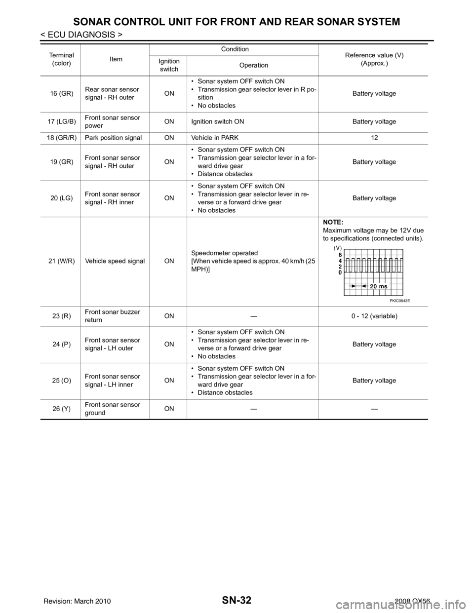
21 (W/R) Vehicle speed signal ON Speedometer operated
[When vehicle speed is approx. 40 km/h (25
MPH)]NOTE:
Maximum voltage may be 12V due
to specifications (connected units).
23 (R) Front sonar buzzer
return ON
— 0 - 12 (variable)
24 (P) Front sonar sensor
signal - LH outer
ON• Sonar system OFF switch ON
• Transmission gear selector lever in re-
verse or a forward drive gear
• No obstacles Battery voltage
25 (O) Front sonar sensor
signal - LH inner
ON• Sonar system OFF switch ON
• Transmission gear selector lever in a for-
ward drive gear
• Distance obstacles Battery voltage
26 (Y) Front sonar sensor
ground ON
— —
Te r m i n a l
(color) Item Condition
Reference value (V)
(Approx.)
Ignition
switch Operation
PKIC0643E
Revision: March 2010
2008 QX56
Page 3530 of 4083

STR-1
ENGINE
C
DE
F
G H
I
J
K L
M
SECTION STR
A
STR
N
O P
CONTENTS
STARTING SYSTEM
PRECAUTION ....... ........................................2
PRECAUTIONS .............................................. .....2
Precaution for Supplemental Restraint System
(SRS) "AIR BAG" and "SEAT BELT PRE-TEN-
SIONER" ............................................................. ......
2
Precaution Necessary for Steering Wheel Rota-
tion After Battery Disconnect ............................... ......
2
Precaution for Power Generation Variable Voltage
Control System ..........................................................
3
PREPARATION ............................................4
PREPARATION .............................................. .....4
Special Service Tool ........................................... ......4
Commercial Service Tool ..........................................4
BASIC INSPECTION ....................................5
DIAGNOSIS AND REPAIR WORKFLOW ..... .....5
Work Flow ........................................................... ......5
FUNCTION DIAGNOSIS ...............................8
STARTING SYSTEM ...................................... .....8
System Diagram .................................................. ......8
System Description ...................................................8
Component Parts Location ........................................8
Component Description ............................................9
COMPONENT DIAGNOSIS .........................10
B TERMINAL CIRCUIT .....................................10
Description ........................................................... ....10
Diagnosis Procedure ...............................................10
S CONNECTOR CIRCUIT .................................11
Description ...............................................................11
Diagnosis Procedure ...............................................11
STARTING SYSTEM .........................................12
Wiring Diagram .................................................... ....12
SYMPTOM DIAGNOSIS ..............................16
STARTING SYSTEM .........................................16
Symptom Table ................................................... ....16
ON-VEHICLE REPAIR .................................17
STARTER MOTOR ...........................................17
Removal and Installation ..................................... ....17
SERVICE DATA AND SPECIFICATIONS
(SDS) ............... .......................................... ...
18
STARTER MOTOR ...........................................18
Starter .................................................................. ....18
Revision: March 2010 2008 QX56