2008 INFINITI QX56 ECU
[x] Cancel search: ECUPage 1786 of 4083
![INFINITI QX56 2008 Factory Service Manual PRECAUTIONSEC-487
< PRECAUTION > [VK56DE]
C
D
E
F
G H
I
J
K L
M A
EC
NP
O
5. When the repair work is completed, return the ignition switch to the
″LOCK ″ position before connecting
the battery ca INFINITI QX56 2008 Factory Service Manual PRECAUTIONSEC-487
< PRECAUTION > [VK56DE]
C
D
E
F
G H
I
J
K L
M A
EC
NP
O
5. When the repair work is completed, return the ignition switch to the
″LOCK ″ position before connecting
the battery ca](/manual-img/42/57030/w960_57030-1785.png)
PRECAUTIONSEC-487
< PRECAUTION > [VK56DE]
C
D
E
F
G H
I
J
K L
M A
EC
NP
O
5. When the repair work is completed, return the ignition switch to the
″LOCK ″ position before connecting
the battery cables. (At this time, the steering lock mechanism will engage.)
6. Perform a self-diagnosis check of al l control units using CONSULT-III.
On Board Diagnosis (OBD) System of Engine and A/TINFOID:0000000001351222
The ECM has an on board diagnostic system . It will light up the malfunction indicator lamp (MIL) to warn the
driver of a malfunction causing emission deterioration.
CAUTION:
• Be sure to turn the ignition switch OFF and di sconnect the negative battery cable before any repair
or inspection work. The open/short circuit of re lated switches, sensors, solenoid valves, etc. will
cause the MIL to light up.
• Be sure to connect and lock the connectors secure ly after work. A loose (unlocked) connector will
cause the MIL to light up due to the open circuit. (Be sure the connector is free from water, grease,
dirt, bent terminals, etc.)
• Certain systems and components, especially those related to OBD, may use a new style slide-lock-
ing type harness connector. For description and how to disconnect, refer to PG-65
.
• Be sure to route and secure the harnesses properly after work. The interference of the harness with
a bracket, etc. may cause the MIL to li ght up due to the short circuit.
• Be sure to connect rubber tubes properly afte r work. A misconnected or disconnected rubber tube
may cause the MIL to light up due to the malfuncti on of the EVAP system or fuel injection system,
etc.
• Be sure to erase the unnecessary malfunction information (repairs completed) from the ECM and TCM (Transmission control module) before returning the vehicle to the customer.
PrecautionINFOID:0000000006211821
•Always use a 12 volt battery as power source.
• Do not attempt to disconnect battery cables while engine is
running.
• Before connecting or disc onnecting the ECM harness con-
nector, turn ignition switch OFF and disconnect negative bat-
tery cable. Failure to do so may damage the ECM because
battery voltage is applied to ECM even if ignition switch is
turned OFF.
• Before removing parts, turn ig nition switch OFF and then dis-
connect negative battery cable.
• Do not disassemble ECM.
• If a battery cable is disconnected, the memory will return to
the ECM value.
The ECM will now start to sel f-control at its initial value.
Engine operation can vary slight ly when the terminal is dis-
connected. However, this is not an indication of a malfunc-
tion. Do not replace parts because of a slight variation.
• If the battery is disconnected, the following emission-related
diagnostic information will be lost within 24 hours.
- Diagnostic trouble codes
- 1st trip diagnostic trouble codes
- Freeze frame data
- 1st trip freeze frame data
- System readiness test (SRT) codes
- Test values
-
Presumed ethanol mixture ratio
SEF289H
PBIB1164E
Revision: March 2010 2008 QX56
Page 1787 of 4083
![INFINITI QX56 2008 Factory Service Manual EC-488
< PRECAUTION >[VK56DE]
PRECAUTIONS
•
When connecting ECM harness co nnector, fasten it securely
with a lever as far as it will go as shown in the figure.
• When connecting or disconnect in INFINITI QX56 2008 Factory Service Manual EC-488
< PRECAUTION >[VK56DE]
PRECAUTIONS
•
When connecting ECM harness co nnector, fasten it securely
with a lever as far as it will go as shown in the figure.
• When connecting or disconnect in](/manual-img/42/57030/w960_57030-1786.png)
EC-488
< PRECAUTION >[VK56DE]
PRECAUTIONS
•
When connecting ECM harness co nnector, fasten it securely
with a lever as far as it will go as shown in the figure.
• When connecting or disconnect ing pin connectors into or
from ECM, take care not to damage pin terminals (bend or
break).
Make sure that there are not any bends or breaks on ECM pin
terminal, when connecting pin connectors.
• Securely connect ECM harness connectors.
A poor connection can cause an extremely high (surge) volt-
age to develop in coil and co ndenser, thus resulting in dam-
age to ICs.
• Keep engine control system harness at least 10 cm (4 in) away
from adjacent harness, to preven t engine control system mal-
functions due to receiving external noise, degraded operation
of ICs, etc.
• Keep engine control system parts and harness dry.
• Before replacing ECM, perform ECM Terminals and Reference
Value inspection and make sure ECM functions properly.
Refer to EC-429, "
ECM Terminal and Reference Value".
• Handle mass air flow sensor carefully to avoid damage.
• Do not disassemble m ass air flow sensor.
• Do not clean mass air flow sensor with any type of detergent.
• Do not disassemble electric throttle control actuator.
• Even a slight leak in the ai r intake system can cause serious
incidents.
• Do not shock or jar the camshaft position sensor (PHASE),
crankshaft position sensor (POS).
• After performing each TROUBLE DIAGNOSIS, perform DTC
Confirmation Procedure or Overall Function Check.
The DTC should not be displ ayed in the DTC Confirmation
Procedure if the repair is co mpleted. The Overall Function
Check should be a good result if the repair is completed.
BBIA0387E
PBIB0090E
MEF040D
SEF217U
Revision: March 2010 2008 QX56
Page 1795 of 4083
![INFINITI QX56 2008 Factory Service Manual EC-496
< ON-VEHICLE MAINTENANCE >[VK56DE]
EVAP LEAK CHECK
EVAP LEAK CHECK
How to Detect Fuel Vapor LeakageINFOID:0000000001351309
CAUTION:
• Never use compressed air or a high pressure pump.
• Do INFINITI QX56 2008 Factory Service Manual EC-496
< ON-VEHICLE MAINTENANCE >[VK56DE]
EVAP LEAK CHECK
EVAP LEAK CHECK
How to Detect Fuel Vapor LeakageINFOID:0000000001351309
CAUTION:
• Never use compressed air or a high pressure pump.
• Do](/manual-img/42/57030/w960_57030-1794.png)
EC-496
< ON-VEHICLE MAINTENANCE >[VK56DE]
EVAP LEAK CHECK
EVAP LEAK CHECK
How to Detect Fuel Vapor LeakageINFOID:0000000001351309
CAUTION:
• Never use compressed air or a high pressure pump.
• Do not exceed 4.12 kPa (0.042 kg/cm
2, 0.6 psi) of pressure in EVAP system.
NOTE:
• Do not start engine.
• Improper installation of EVAP service port adapter to the EVAP service port may cause a leak.
WITH CONSULT-IIl
1. Attach the EVAP service port adapter securely to the EVAP service port.
2. Also attach the pressure pump and hose to the EVAP service port adapter.
3. Turn ignition switch ON.
4. Select the “EVAP SYSTEM CLOSE” of “WORK SUPPORT MODE” with CONSULT-IIl.
5. Touch “START”. A bar graph (Pressure indicating display) will appear on the screen.
6. Apply positive pressure to the EVAP system until t he pressure indicator reaches the middle of the bar
graph.
7. Remove EVAP service port adapter and hose with pressure pump.
8. Locate the leak using a leak detector. Refer to EC-37, "
Descrip-
tion".
WITHOUT CONSULT-IIl
1. Attach the EVAP service port adapter securely to the EVAP ser- vice port.
2. Also attach the pressure pump with pressure gauge to the EVAP service port adapter.
SEF200U
BBIA0366E
SEF462UA
Revision: March 2010 2008 QX56
Page 1817 of 4083
EM-14
< ON-VEHICLE MAINTENANCE >
DRIVE BELTS
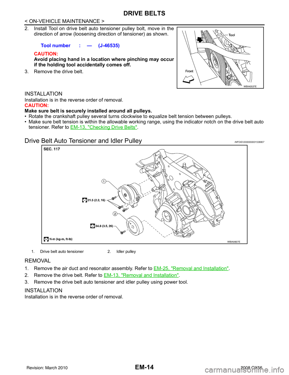
2. Install Tool on drive belt auto tensioner pulley bolt, move in thedirection of arrow (loosening direction of tensioner) as shown.
CAUTION:
Avoid placing hand in a locatio n where pinching may occur
if the holding tool accidentally comes off.
3. Remove the drive belt.
INSTALLATION
Installation is in the reverse order of removal.
CAUTION:
Make sure belt is securely installed around all pulleys.
• Rotate the crankshaft pulley several turns clockwise to equalize belt tension between pulleys.
• Make sure belt tension is within the allowable working range, using the indicator notch on the drive belt auto tensioner. Refer to EM-13, "
Checking Drive Belts".
Drive Belt Auto Tensioner and Idler PulleyINFOID:0000000001538807
REMOVAL
1. Remove the air duct and resonator assembly. Refer to EM-25, "Removal and Installation".
2. Remove the drive belt. Refer to EM-13, "
Removal and Installation".
3. Remove the drive belt auto tensioner and idler pulley using power tool.
INSTALLATION
Installation is in the reverse order of removal. Tool number : — (J-46535)
WBIA0537E
WBIA0607E
1. Drive belt auto tensioner
2. Idler pulley
Revision: March 2010 2008 QX56
Page 1845 of 4083
EM-42
< ON-VEHICLE REPAIR >
FUEL INJECTOR AND FUEL TUBE
• Lubricate O-ring with new engine oil.
• Do not clean O-ring with solvent.
• Make sure that O-ring and its mating part are free of foreign material.
• When installing O-ring, be careful not to scratch it with tool or fingernails. Also be careful not to
twist or stretch O-ring. If O-ring was stretc hed while it was being attached, do not insert it
quickly into fuel tube.
• Insert O-ring straight into fuel tube. Do not angle or twist it.
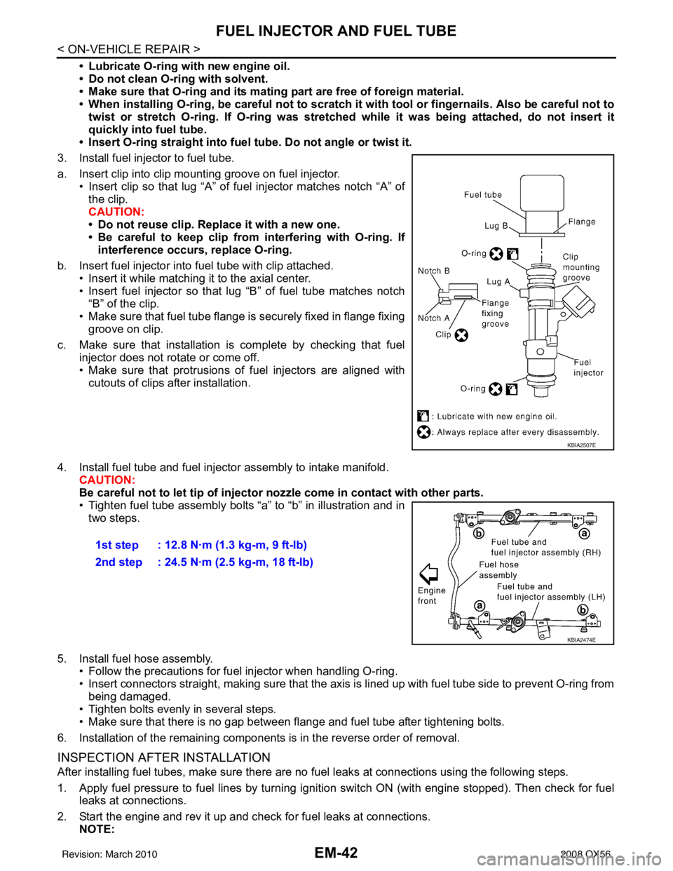
3. Install fuel injector to fuel tube.
a. Insert clip into clip mounting groove on fuel injector. • Insert clip so that lug “A” of fuel injector matches notch “A” ofthe clip.
CAUTION:
• Do not reuse clip. Replace it with a new one.
• Be careful to keep clip from interfering with O-ring. Ifinterference occurs, replace O-ring.
b. Insert fuel injector into fuel tube with clip attached. • Insert it while matching it to the axial center.
• Insert fuel injector so that lug “B” of fuel tube matches notch
“B” of the clip.
• Make sure that fuel tube flange is securely fixed in flange fixing groove on clip.
c. Make sure that installation is complete by checking that fuel injector does not rotate or come off.
• Make sure that protrusions of fuel injectors are aligned withcutouts of clips after installation.
4. Install fuel tube and fuel injector assembly to intake manifold. CAUTION:
Be careful not to let tip of injector nozzle come in contact with other parts.
• Tighten fuel tube assembly bolts “a” to “b” in illustration and in
two steps.
5. Install fuel hose assembly. • Follow the precautions for fuel injector when handling O-ring.
• Insert connectors straight, making sure that the axis is lined up with fuel tube side to prevent O-ring from
being damaged.
• Tighten bolts evenly in several steps.
• Make sure that there is no gap between flange and fuel tube after tightening bolts.
6. Installation of the remaining components is in the reverse order of removal.
INSPECTION AFTER INSTALLATION
After installing fuel tubes, make sure there are no fuel leaks at connections using the following steps.
1. Apply fuel pressure to fuel lines by turning ignition switch ON (with engine stopped). Then check for fuel leaks at connections.
2. Start the engine and rev it up and check for fuel leaks at connections. NOTE:
KBIA2507E
1st step : 12.8 N·m (1.3 kg-m, 9 ft-lb)
2nd step : 24.5 N·m (2.5 kg-m, 18 ft-lb)
KBIA2474E
Revision: March 2010 2008 QX56
Page 1849 of 4083
EM-46
< ON-VEHICLE REPAIR >
TIMING CHAIN
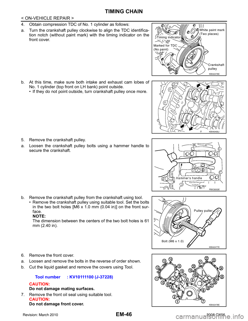
4. Obtain compression TDC of No. 1 cylinder as follows:
a. Turn the crankshaft pulley clockwise to align the TDC identifica-tion notch (without paint mark) with the timing indicator on the
front cover.
b. At this time, make sure both intake and exhaust cam lobes of No. 1 cylinder (top front on LH bank) point outside.
• If they do not point outside, turn crankshaft pulley once more.
5. Remove the crankshaft pulley.
a. Loosen the crankshaft pulley bolts using a hammer handle to secure the crankshaft.
b. Remove the crankshaft pulley from the crankshaft using tool. • Remove the crankshaft pulley using suitable tool. Set the boltsin the two bolt holes [M6 x 1.0 mm (0.04 in)] on the front sur-
face.
NOTE:
The dimension between the centers of the two bolt holes is 61
mm (2.40 in).
6. Remove the front cover.
a. Loosen and remove the bolts in the reverse of order shown.
b. Cut the liquid gasket and remove the covers using Tool. CAUTION:
Do not damage mating surfaces.
7. Remove the front oil seal using suitable tool. CAUTION:
Do not damage front cover.
KBIA2476E
KBIA0400J
PBIC0053E
KBIA2477E
Tool number : KV10111100 (J-37228)
KBIA2478E
Revision: March 2010 2008 QX56
Page 1850 of 4083
TIMING CHAINEM-47
< ON-VEHICLE REPAIR >
C
DE
F
G H
I
J
K L
M A
EM
NP
O
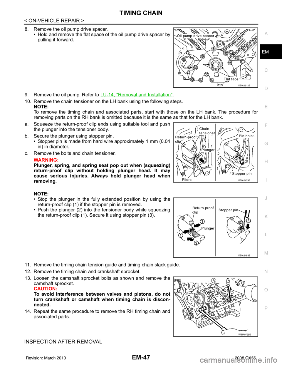
8. Remove the oil pump drive spacer.
• Hold and remove the flat space of the oil pump drive spacer bypulling it forward.
9. Remove the oil pump. Refer to LU-14, "
Removal and Installation".
10. Remove the chain tensioner on the LH bank using the following steps. NOTE:
To remove the timing chain and associated parts, start with those on the LH bank. The procedure for
removing parts on the RH bank is omitted because it is the same as that for the LH bank.
a. Squeeze the return-proof clip ends using suitable tool and push the plunger into the tensioner body.
b. Secure the plunger using stopper pin. • Stopper pin is made from hard wire approximately 1 mm (0.04in) in diameter.
c. Remove the bolts and chain tensioner.
WARNING:
Plunger, spring, an d spring seat pop out when (squeezing)
return-proof clip without holding plunger head. It may
cause serious injuries. Always hold plunger head when
removing.
NOTE:
• Stop the plunger in the fully extended position by using the
return-proof clip (1) if the stopper pin is removed.
• Push the plunger (2) into the tensioner body while squeezing
the return-proof clip (1). Secure it using stopper pin (3).
11. Remove the timing chain tension guide and timing chain slack guide.
12. Remove the timing chain and crankshaft sprocket.
13. Loosen the camshaft sprocket bolts as shown and remove the camshaft sprocket.
CAUTION:
To avoid interference between valves and pistons, do not
turn crankshaft or camshaft wh en timing chain is discon-
nected.
14. Repeat the same procedure to remove the RH timing chain and associated parts.
INSPECTION AFTER REMOVAL
KBIA2512E
KBIA2479E
KBIA2483E
WBIA0799E
Revision: March 2010 2008 QX56
Page 1858 of 4083
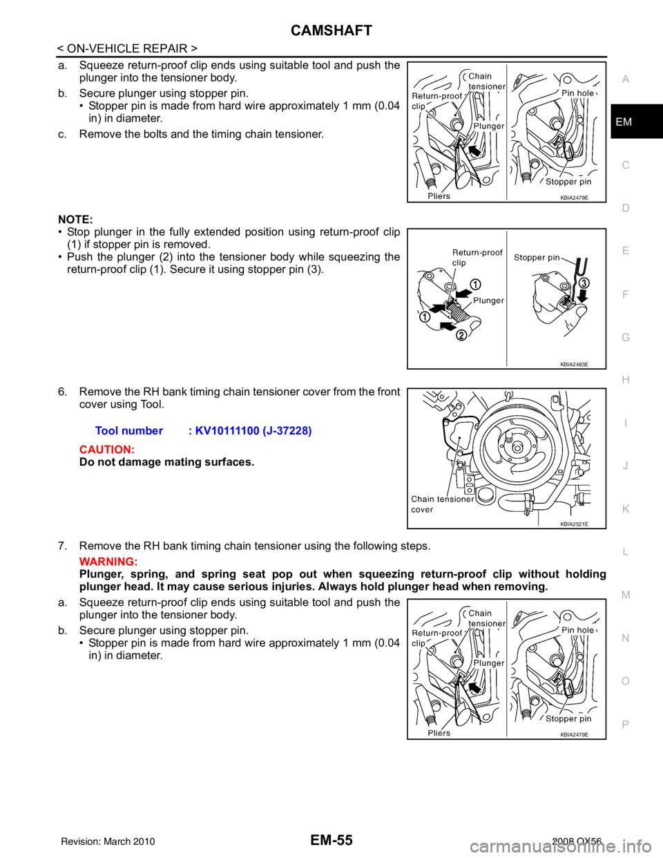
CAMSHAFTEM-55
< ON-VEHICLE REPAIR >
C
DE
F
G H
I
J
K L
M A
EM
NP
O
a. Squeeze return-proof clip ends using suitable tool and push the
plunger into the tensioner body.
b. Secure plunger using stopper pin. • Stopper pin is made from hard wire approximately 1 mm (0.04in) in diameter.
c. Remove the bolts and the timing chain tensioner.
NOTE:
• Stop plunger in the fully extended position using return-proof clip (1) if stopper pin is removed.
• Push the plunger (2) into the tensioner body while squeezing the return-proof clip (1). Secure it using stopper pin (3).
6. Remove the RH bank timing chain tensioner cover from the front cover using Tool.
CAUTION:
Do not damage mating surfaces.
7. Remove the RH bank timing chain tensioner using the following steps. WARNING:
Plunger, spring, and spring seat pop out when squeezing return -proof clip without holding
plunger head. It may cause serious injuries. Always hold plunger head when removing.
a. Squeeze return-proof clip ends using suitable tool and push the plunger into the tensioner body.
b. Secure plunger using stopper pin. • Stopper pin is made from hard wire approximately 1 mm (0.04in) in diameter.
KBIA2479E
KBIA2483E
Tool number : KV10111100 (J-37228)
KBIA2521E
KBIA2479E
Revision: March 2010 2008 QX56