2008 INFINITI QX56 ECU
[x] Cancel search: ECUPage 2198 of 4083

GW-8
< ON-VEHICLE REPAIR >
REAR WINDOW GLASS AND MOLDING
INSTALLATION
Installation is in the reverse order of removal.
GLASS STAY
Disposal
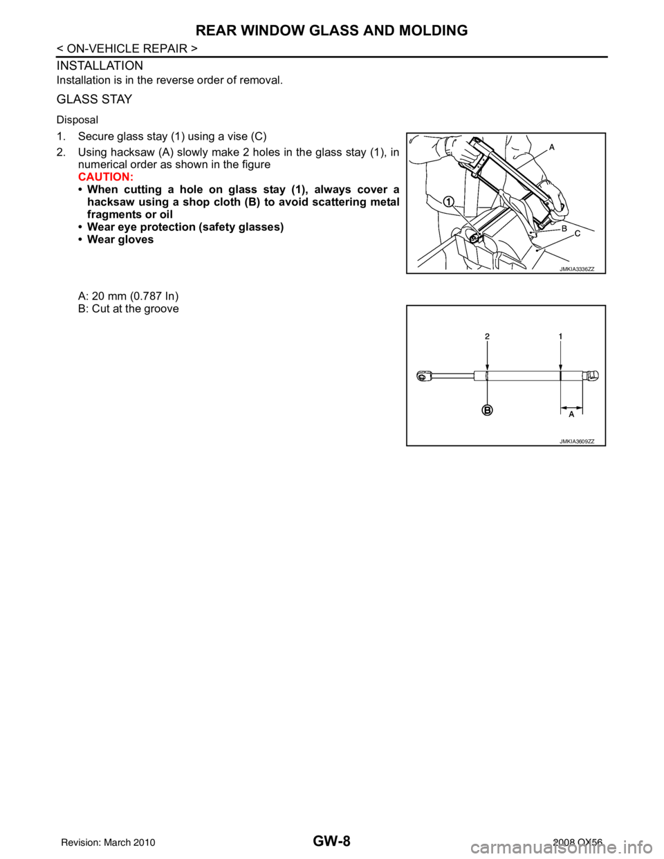
1. Secure glass stay (1) using a vise (C)
2. Using hacksaw (A) slowly make 2 holes in the glass stay (1), innumerical order as shown in the figure
CAUTION:
• When cutting a hole on gl ass stay (1), always cover a
hacksaw using a shop cloth (B) to avoid scattering metal
fragments or oil
• Wear eye protection (safety glasses)
• Wear gloves
A: 20 mm (0.787 In)
B: Cut at the groove
JMKIA3336ZZ
JMKIA3609ZZ
Revision: March 2010 2008 QX56
Page 2200 of 4083

GW-10
< ON-VEHICLE REPAIR >
FRONT DOOR GLASS AND REGULATOR
NOTE:
If any of the following work has been done, reset the power window motor limit switch.
• Removal and installation of the regulator assembly.
• Removal and installation of the power window motor from the regulator.
• Installation of a new glass window.
• Installation of a new glass run.
Check the label on the power window motor for the part number. If the power window motor part number
matches one of the following, the motor must be removed from the regulator and the limit switch reset using
the "INSTALLATION WITHOUT RESET SWITCH" pr ocedure in "FRONT DOOR GLASS REGULATOR
ASSEMBLY".
• 80730-ZT01A
• 80731-ZT01A
• 80730-ZM70B
• 80731-ZM70B
If the power window motor part number does not match one of the part numbers above, the limit switch can be
reset in the vehicle using the "INSTA LLATION WITH RESET SWITCH" procedure.
NOTE:
• The label can be checked with the power window motor in the vehicle by using a mirror.
• Some of the power window motors with the part num bers above may appear to have a reset switch, but it will
not reset the limit switch.
Fitting Inspection
• Check that the glass is securely fit into the glass run groove.
• Lower the glass slightly [approximately 10 to 20 mm (0 .39 to 0.79 in)] and check that the clearance to the
sash is parallel. If the clearance between the glass and sash is not parallel, loosen the regulator bolts, guide
rail bolts, and glass and guide rail bolts to correct the glass position.
FRONT DOOR GLASS REGULATOR ASSEMBLY
Removal
1. Remove the front door finisher panel. Refer to INT-11, "Removal and Installation".
2. Position aside the vapor barrier.
3. Remove the hole cover over rear glass bolt.
4. Operate the power window main switch to raise/ lower the door window until the glass bolts can be seen.
5. Remove the inside seal.
6. Remove the glass bolts.
7. Raise the front door glass and hold it in place with suitable tool.
8. Disconnect the harness connector fr om the regulator assembly.
9. Remove the bolts and the regulator assembly.
Disassembly And Assembly
Remove the regulator motor from the regulator assembly.
Inspection After Removal
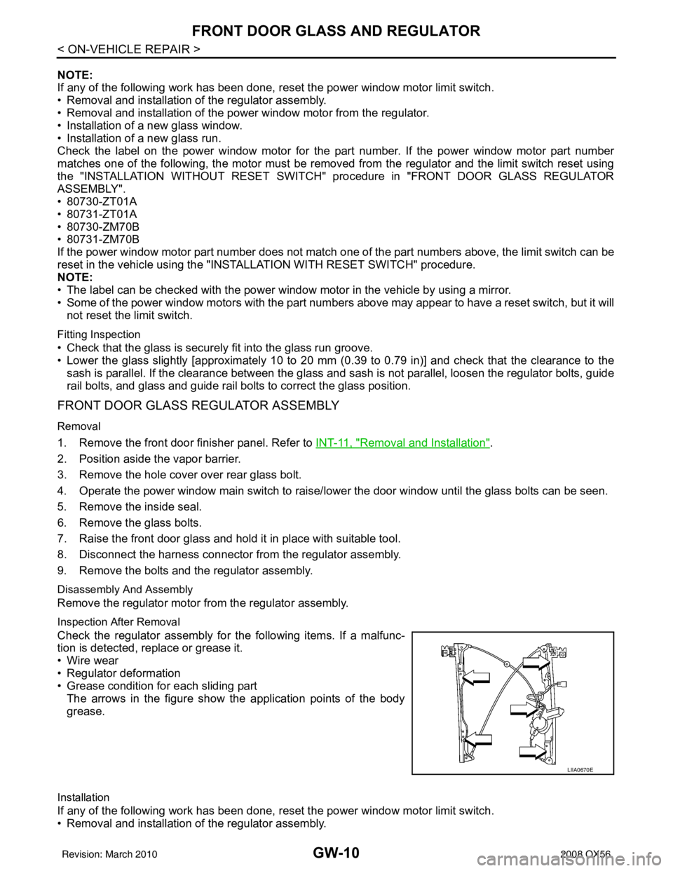
Check the regulator assembly for the following items. If a malfunc-
tion is detected, replace or grease it.
• Wire wear
• Regulator deformation
• Grease condition for each sliding part The arrows in the figure show the application points of the body
grease.
Installation
If any of the following work has been done, reset the power window motor limit switch.
• Removal and installation of the regulator assembly.
LIIA0670E
Revision: March 2010 2008 QX56
Page 2201 of 4083

FRONT DOOR GLASS AND REGULATORGW-11
< ON-VEHICLE REPAIR >
C
DE
F
G H
I
J
L
M A
B
GW
N
O P
• Removal and installation of the power window motor from the regulator.
• Installation of a new glass window.
• Installation of a new glass run.
Check the label on the power window motor for the part number. If the power window motor part number
matches one of the following, the limit switch must be reset using the "INSTALLATION WITHOUT RESET
SWITCH" procedure.
• 80730-ZT01A
• 80731-ZT01A
• 80730-ZM70B
• 80731-ZM70B
If the power window motor part number does not match one of the part numbers above, the limit switch must
be reset using the "INSTALLATION WITH RESET SWITCH" procedure.
NOTE:
Some of the power window motors with the part num bers above may appear to have a reset switch, but it will
not reset the limit switch.
INSTALLATION WITHOUT RESET SWITCH - (Motors listed above)
Check the label on the power window motor for the pa rt number. If the power window motor part number does
not match one of the above, use the "INS TALLATION WITH RESET SWITCH" procedure.
NOTE:
Some of the power window motors may appear to have a re set switch, but it will not reset the limit switch.
1. Connect the door harness connector to the power window motor, and rotate the motor more than 5 turns
in the glass raising (up) direction.
2. Install the power window motor onto the regulator.
3. Install the regulator assembly into the door and secure regulator assembly with the nuts and bolt.
4. Install the glass into the door and align with the regulator, then install the glass bolts.
5. Raise the glass to the top position. CAUTION:
Do not operate the glass automatical ly to raise the glass to the top.
6. Reposition the vapor barrier.
7. Install the front door finisher panel. Refer to INT-11, "
Removal and Installation".
INSTALLATION WITH RESET SWITCH - (Motors not listed above)
1. Install the power window motor onto the regulator.
2. Install the regulator assembly into the door and secure regulator assembly with the nuts and bolt.
3. Connect the door harness connector to the power window motor.
4. Install the glass into the door and align with the regulator, then install the glass bolts.
Power Window Motor Up Direction
• LH motor rotate counterclockwise
• RH motor rotate clockwise
Regulator assembly nuts
and bolt : 7.5 N·m (0.77 kg-m, 66 in-lb)
Glass bolts : 6.1 N·m (0.62 kg-m, 54 in-lb)
Regulator assembly nuts
and bolt : 7.5 N·m (0.77 kg-m, 66 in-lb)
Glass bolts : 6.1 N·m (0.62 kg-m, 54 in-lb)
Revision: March 2010 2008 QX56
Page 2203 of 4083

REAR DOOR GLASS AND REGULATORGW-13
< ON-VEHICLE REPAIR >
C
DE
F
G H
I
J
L
M A
B
GW
N
O P
REAR DOOR GLASS AND REGULATOR
Removal and InstallationINFOID:0000000001608356
REAR DOOR GLASS
Removal
1. Remove the rear door finisher. Refer to INT-11, "Removal and Installation".
2. Temporarily reconnect the power window switch.
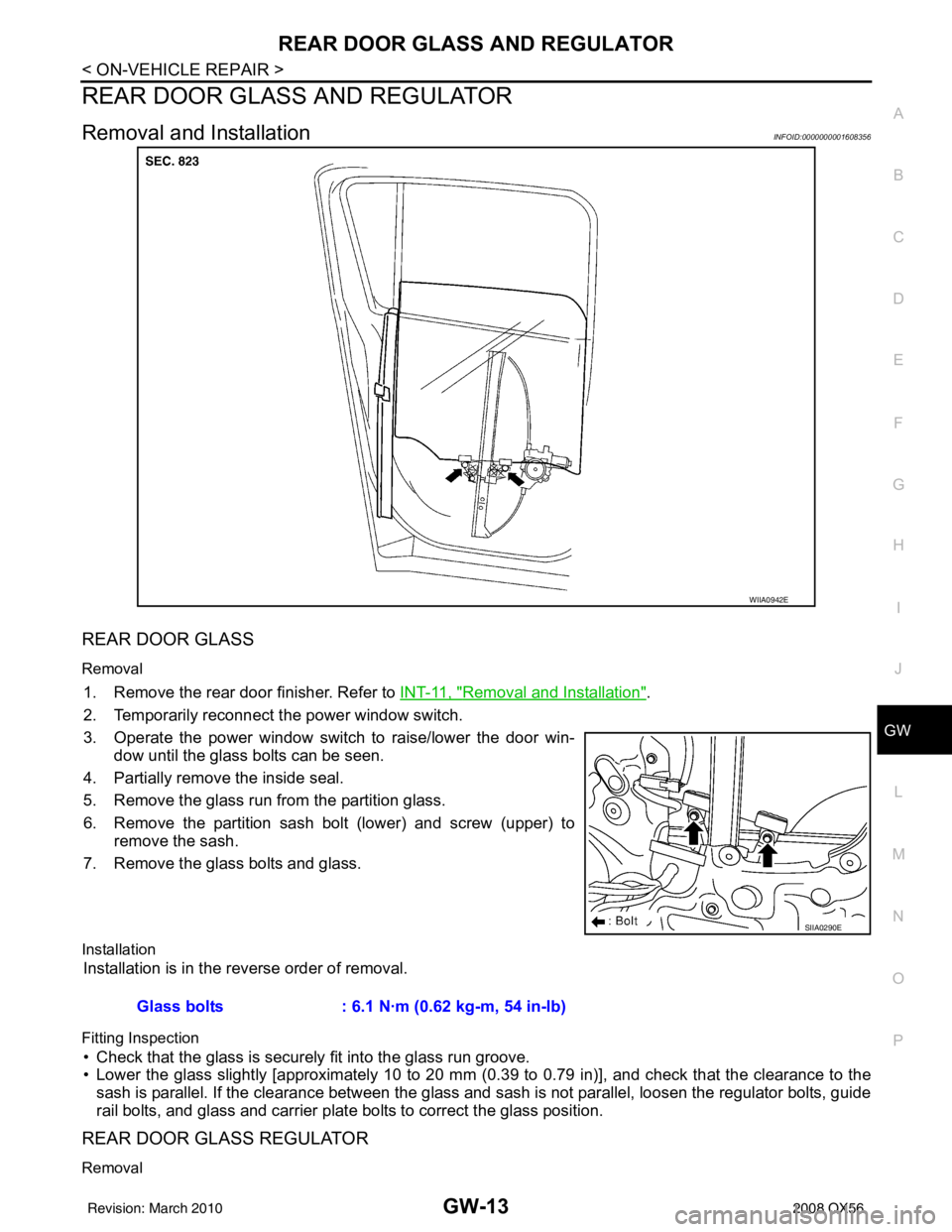
3. Operate the power window switch to raise/lower the door win- dow until the glass bolts can be seen.
4. Partially remove the inside seal.
5. Remove the glass run from the partition glass.
6. Remove the partition sash bolt (lower) and screw (upper) to remove the sash.
7. Remove the glass bolts and glass.
Installation
Installation is in the reverse order of removal.
Fitting Inspection
• Check that the glass is securely fit into the glass run groove.
• Lower the glass slightly [approximately 10 to 20 mm (0 .39 to 0.79 in)], and check that the clearance to the
sash is parallel. If the clearance between the glass and sash is not parallel, loosen the regulator bolts, guide
rail bolts, and glass and carrier plate bolts to correct the glass position.
REAR DOOR GLASS REGULATOR
Removal
WIIA0942E
SIIA0290E
Glass bolts : 6.1 N·m (0.62 kg-m, 54 in-lb)
Revision: March 2010 2008 QX56
Page 2255 of 4083

HAC-2
MAGNET CLUTCH ............................................71
System Description .............................................. ...71
Magnet Clutch Component Function Check ........ ...71
Magnet Clutch Diagnosis Procedure ................... ...72
WATER VALVE CIRCUIT ..................................76
Description ........................................................... ...76
Water Valve Diagnosis Procedure ..........................76
AMBIENT SENSOR ...........................................78
Component Description ....................................... ...78
Ambient Sensor Diagnosis Procedure ....................78
Ambient Sensor Component Inspection .................79
IN-VEHICLE SENSOR .......................................81
Component Description ....................................... ...81
In-Vehicle Sensor Diagnosis Procedure .................81
In-Vehicle Sensor Component Inspection ..............83
OPTICAL SENSOR ...........................................84
Component Description ..........................................84
Optical Sensor Diagnosis Procedure ......................84
INTAKE SENSOR ..............................................86
System Description .............................................. ...86
Intake Sensor Diagnosis Procedure .......................86
Intake Sensor Component Inspection ................. ...87
POWER SUPPLY AND GROUND CIRCUIT
FOR CONTROLLER ..........................................
88
Component Description ....................................... ...88
A/C Auto Amp. Component Function Check ..........88
A/C Auto Amp Power and Ground Diagnosis Pro-
cedure .....................................................................
89
ECU DIAGNOSIS .......................................90
AIR CONDITIONER CONTROL ..................... ...90
A/C Auto Amp. Terminals Reference Values ..........90
Wiring Diagram .................................................... ...92
SYMPTOM DIAGNOSIS ...........................108
AIR CONDITIONER CONTROL ..................... ..108
Symptom Matrix Chart ........................................ .108
INSUFFICIENT COOLING ................................109
Component Function Check ................................ .109
Diagnostic Work Flow ...........................................110
Performance Chart ................................................113
Trouble Diagnoses for Abnormal Pressure ...........114
INSUFFICIENT HEATING ................................117
Component Function Check .................................117
NOISE ...............................................................119
Component Function Check ................................ .119
MEMORY FUNCTION DOES NOT OPERATE ..121
Memory Function Check ...................................... .121
PRECAUTION ...........................................122
PRECAUTIONS .............................................. ..122
Precaution for Supplemental Restraint System
(SRS) "AIR BAG" and "SEAT BELT PRE-TEN-
SIONER" .............................................................. .
122
Working with HFC-134a (R-134a) ........................ .122
Precaution for Service Equipment ........................123
Revision: March 2010 2008 QX56
Page 2273 of 4083
![INFINITI QX56 2008 Factory Service Manual HAC-20
< FUNCTION DIAGNOSIS >[AUTOMATIC AIR CONDITIONER]
DIAGNOSIS SYSTEM (HVAC)
DIAGNOSIS SYSTEM (HVAC)
CONSULT-III Function (HVAC)INFOID:0000000001679777
CONSULT-III can display each diagnostic item INFINITI QX56 2008 Factory Service Manual HAC-20
< FUNCTION DIAGNOSIS >[AUTOMATIC AIR CONDITIONER]
DIAGNOSIS SYSTEM (HVAC)
DIAGNOSIS SYSTEM (HVAC)
CONSULT-III Function (HVAC)INFOID:0000000001679777
CONSULT-III can display each diagnostic item](/manual-img/42/57030/w960_57030-2272.png)
HAC-20
< FUNCTION DIAGNOSIS >[AUTOMATIC AIR CONDITIONER]
DIAGNOSIS SYSTEM (HVAC)
DIAGNOSIS SYSTEM (HVAC)
CONSULT-III Function (HVAC)INFOID:0000000001679777
CONSULT-III can display each diagnostic item using the diagnostic test modes shown following.
SELF-DIAGNOSIS
Display Item List
DATA MONITOR
Display Item List
Diagnostic mode
Description
SELF-DIAG RESULTS Displays A/C au to amp. self-diagnosis results.
DATA MONITOR Displays A/C auto amp. input/output data in real time.
CAN DIAG SUPPORT MNTR The result of transmit/receive diagnosis of CAN communication can be read. ECU PART NUMBER A/C auto amp. part number can be read.
DTC Description
Reference page
B2573 Battery voltage out of range CHG-10, "
Inspection Procedure"
B2578 In-vehicle sensor circuit out of range (low)
HAC-81, "In-Vehicle Sensor Diagnosis Procedure"B2579 In-vehicle sensor circuit out of range (high)
B257B Ambient sensor circuit short HAC-78, "
Ambient Sensor Diagnosis Procedure"B257C Ambient sensor circuit open
B257F Optical sensor (Driver) circuit open or short HAC-84, "
Optical Sensor Diagnosis Procedure".
B2580 Optical sensor (Passenger) circuit open or short
B2581 Intake sensor circuit short HAC-86, "
Intake Sensor Diagnosis Procedure"B2582 Intake sensor circuit open
U1000 CAN bus fault LAN-14, "
Trouble Diagnosis Flow Chart"
Monitor itemValue Contents
BATT VIA CAN "V" Displays battery voltage signal.
IGN VIA CAN "ON/OFF" Displays ignition switch signal.
DVR SUNLD SEN "w/m2" Displays optical sensor (driver) signal.
PAS SUNLD SEN "w/m2" Displays optical sensor (passenger) signal.
AMB TEMP SEN "° C" Displays ambient sensor signal.
EVAP TEMP SEN "° C" Displays intake sensor signal.
INCAR TMP SEN "° C" Displays in-vehicle sensor signal.
RR TEMPSET FR "V" Displays air mix door (front) set point signal.
RR TEMPSET RR "V" Displays air mix door (rear) set point signal.
MODE FDBCK "V" Displays mode door motor feedback signal.
DVR MIX FDBCK "V" Displays air mix door motor (driver) feedback signal.
PAS MIX FDBCK "V" Displays air mix door motor (passenger) feedback signal.
RR FDBCK "V" Displays air mix door motor (rear) feedback signal.
DEF FDBCK "V" Displays defroster door motor feedback signal.
Revision: March 2010 2008 QX56
Page 2274 of 4083
![INFINITI QX56 2008 Factory Service Manual DIAGNOSIS SYSTEM (BCM)HAC-21
< FUNCTION DIAGNOSIS > [AUTOMATIC AIR CONDITIONER]
C
D
E
F
G H
J
K L
M A
B
HAC
N
O P
DIAGNOSIS SYSTEM (BCM)
CONSULT-III Function (BCM)INFOID:0000000001679778
CONSULT-III c INFINITI QX56 2008 Factory Service Manual DIAGNOSIS SYSTEM (BCM)HAC-21
< FUNCTION DIAGNOSIS > [AUTOMATIC AIR CONDITIONER]
C
D
E
F
G H
J
K L
M A
B
HAC
N
O P
DIAGNOSIS SYSTEM (BCM)
CONSULT-III Function (BCM)INFOID:0000000001679778
CONSULT-III c](/manual-img/42/57030/w960_57030-2273.png)
DIAGNOSIS SYSTEM (BCM)HAC-21
< FUNCTION DIAGNOSIS > [AUTOMATIC AIR CONDITIONER]
C
D
E
F
G H
J
K L
M A
B
HAC
N
O P
DIAGNOSIS SYSTEM (BCM)
CONSULT-III Function (BCM)INFOID:0000000001679778
CONSULT-III can display each diagnostic item us ing the diagnostic test modes shown following.
DATA MONITOR
Display Item List
BCM diagnostic
test item Diagnostic mode
Description
Inspection by part WORK SUPPORT
Supports inspections and adjustments. Commands are transmitted to the BCM for
setting the status suitable for required operation, input/output signals are received
from the BCM and received data is displayed.
DATA MONITOR Displays BCM input/output data in real time. ACTIVE TEST Operation of electrical loads can be checked by sending drive signal to them.
SELF-DIAG RESULTS Displays BCM self-diagnosis results.
CAN DIAG SUPPORT MNTR The result of transmit/receive diagnosis of CAN communication can be read. ECU PART NUMBER BCM part number can be read.
CONFIGURATION Performs BCM configuration read/write functions.
Monitor item name “operation or unit” Contents
IGN ON SW “ON/OFF” Displays “IGN Position (ON)/OFF, ACC Position (OFF)” status as judged from ignition switch signal.
COMP ON SIG “ON/OFF” Displays “COMP (ON)/COMP (OFF)” stat us as judged from air conditioner switch signal.
FAN ON SIG “ON/OFF” Displays “FAN (ON)/FAN (OFF)” status as judged from blower motor switch signal.
Revision: March 2010 2008 QX56
Page 2343 of 4083
![INFINITI QX56 2008 Factory Service Manual HAC-90
< ECU DIAGNOSIS >[AUTOMATIC AIR CONDITIONER]
AIR CONDITIONER CONTROL
ECU DIAGNOSIS
AIR CONDITIONER CONTROL
A/C Auto Amp. Terminals Reference ValuesINFOID:0000000001679827
Measure voltage betwee INFINITI QX56 2008 Factory Service Manual HAC-90
< ECU DIAGNOSIS >[AUTOMATIC AIR CONDITIONER]
AIR CONDITIONER CONTROL
ECU DIAGNOSIS
AIR CONDITIONER CONTROL
A/C Auto Amp. Terminals Reference ValuesINFOID:0000000001679827
Measure voltage betwee](/manual-img/42/57030/w960_57030-2342.png)
HAC-90
< ECU DIAGNOSIS >[AUTOMATIC AIR CONDITIONER]
AIR CONDITIONER CONTROL
ECU DIAGNOSIS
AIR CONDITIONER CONTROL
A/C Auto Amp. Terminals Reference ValuesINFOID:0000000001679827
Measure voltage between each terminal and ground by following
Terminals and Reference Value for A/C auto amp. (1).
A/C AUTO AMP. HARNESS CONNECTOR TERMINAL LAYOUT
TERMINALS AND REFERENCE VALUES FOR A/C AUTO AMP.
AWIIA0170ZZ
AWIIA0568ZZ
Te r m i n a l
No. Wire
color Item
Ignition
switch Condition
Voltage (V)
(Approx.)
1 G/O Optical sensor (driver) ON- 0 - 5V
2 L Air mix door motor (passe nger) ON-Battery voltage
3 P V ref ACTR (ground) ON- 5V
4 W/R Compressor ON signal ON A/C switch OFF
5V
ON A/C switch ON 0V
5 L/R Fan ON signal ON Blower switch OFF
5V
ON Blower switch ON 0V
6 SB Air mix door motor (driver) feedback ON -0 - 5V
7 GR Mode door motor feedback ON- 0 - 5V
8 R/L Illumination + ON Park lamps ONBattery voltage
9 BR Illumination - - Park lamps ON
10 LG/B Defroster door motor feedback ON -0 - 5V
11 L/B Intake sensor ON- 0 - 5V
12 G/Y Variable blower control (rear) ON- 0 - 5V
PIIA2344E
Revision: March 2010 2008 QX56