2008 INFINITI QX56 ECU
[x] Cancel search: ECUPage 1882 of 4083
ENGINE ASSEMBLYEM-79
< REMOVAL AND INSTALLATION >
C
DE
F
G H
I
J
K L
M A
EM
NP
O
4. Remove the engine hood. Refer to
DLK-224, "Removal and Installation of Hood Assembly".
5. Remove the cowl extension. Refer to EXT-18, "
Removal and Installation".
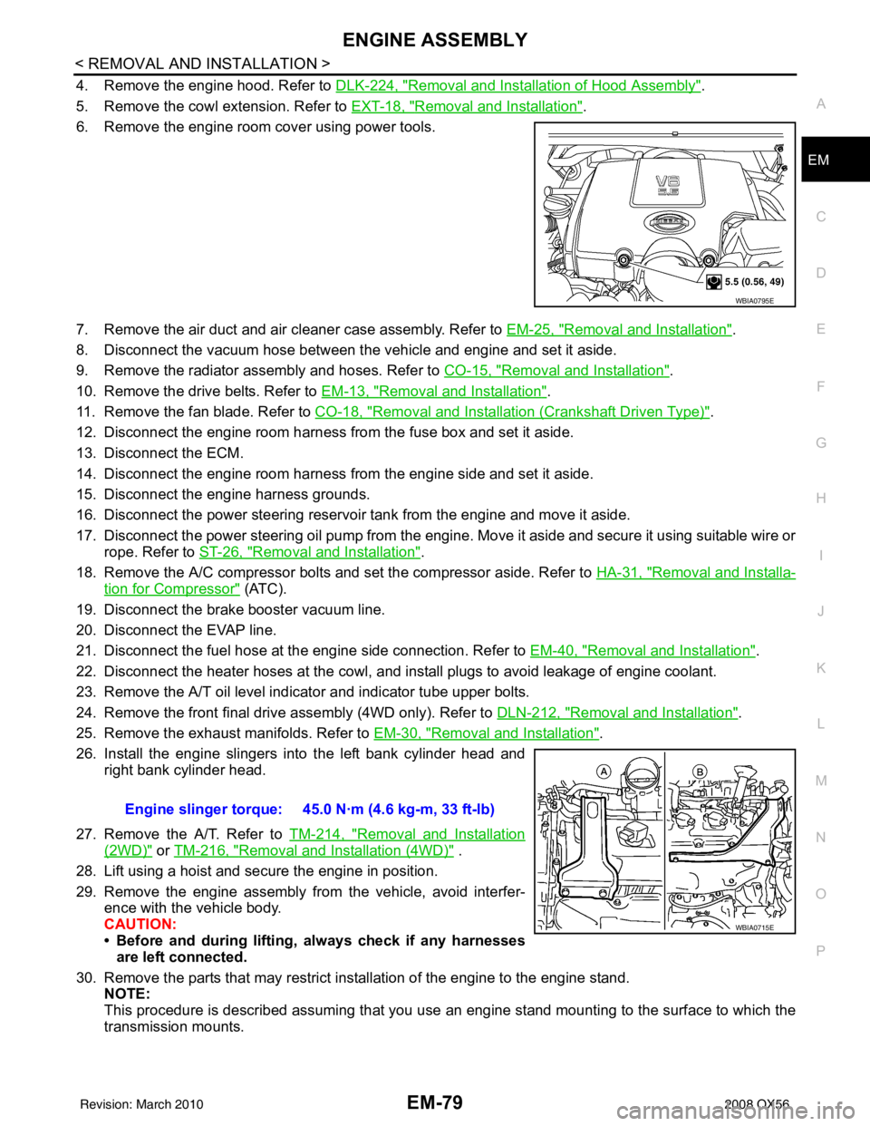
6. Remove the engine room cover using power tools.
7. Remove the air duct and air cleaner case assembly. Refer to EM-25, "
Removal and Installation".
8. Disconnect the vacuum hose between the vehicle and engine and set it aside.
9. Remove the radiator assembly and hoses. Refer to CO-15, "
Removal and Installation".
10. Remove the drive belts. Refer to EM-13, "
Removal and Installation".
11. Remove the fan blade. Refer to CO-18, "
Removal and Installation (Crankshaft Driven Type)".
12. Disconnect the engine room harness from the fuse box and set it aside.
13. Disconnect the ECM.
14. Disconnect the engine room harness from the engine side and set it aside.
15. Disconnect the engine harness grounds.
16. Disconnect the power steering reservoir t ank from the engine and move it aside.
17. Disconnect the power steering oil pump from the engine. Move it aside and secure it using suitable wire or rope. Refer to ST-26, "
Removal and Installation".
18. Remove the A/C compressor bolts and set the compressor aside. Refer to HA-31, "
Removal and Installa-
tion for Compressor" (ATC).
19. Disconnect the brake booster vacuum line.
20. Disconnect the EVAP line.
21. Disconnect the fuel hose at the engine side connection. Refer to EM-40, "
Removal and Installation".
22. Disconnect the heater hoses at the cowl, and in stall plugs to avoid leakage of engine coolant.
23. Remove the A/T oil level indicator and indicator tube upper bolts.
24. Remove the front final drive assembly (4WD only). Refer to DLN-212, "
Removal and Installation".
25. Remove the exhaust manifolds. Refer to EM-30, "
Removal and Installation".
26. Install the engine slingers into the left bank cylinder head and right bank cylinder head.
27. Remove the A/T. Refer to TM-214, "
Removal and Installation
(2WD)" or TM-216, "Removal and Installation (4WD)" .
28. Lift using a hoist and secure the engine in position.
29. Remove the engine assembly from the vehicle, avoid interfer- ence with the vehicle body.
CAUTION:
• Before and during lifting, always check if any harnessesare left connected.
30. Remove the parts that may restrict installation of the engine to the engine stand. NOTE:
This procedure is described assuming that you use an engine stand mounting to the surface to which the
transmission mounts.
WBIA0795E
Engine slinger torque: 45.0 N·m (4.6 kg-m, 33 ft-lb)
WBIA0715E
Revision: March 2010 2008 QX56
Page 1930 of 4083

EXL-2
HEADLAMP (HI) CIRCUIT ................................28
Description ........................................................... ...28
Component Function Check ...................................28
Diagnosis Procedure ..............................................28
HEADLAMP (LO) CIRCUIT ...............................30
Description ........................................................... ...30
Component Function Check ...................................30
Diagnosis Procedure ..............................................30
FRONT FOG LAMP CIRCUIT ...........................32
Description ........................................................... ...32
Component Function Check ...................................32
Diagnosis Procedure ..............................................32
PARKING LAMP CIRCUIT ................................34
Description ........................................................... ...34
Component Function Check ...................................34
Diagnosis Procedure ..............................................34
TURN SIGNAL LAMP CIRCUIT ........................37
Description ........................................................... ...37
Component Function Check ...................................37
Diagnosis Procedure ..............................................37
OPTICAL SENSOR ...........................................40
Description ..............................................................40
Component Function Check ...................................40
Diagnosis Procedure ..............................................40
HEADLAMP AIMING SWITCH ..........................42
Description ........................................................... ...42
Diagnosis Procedure ..............................................42
HEADLAMP .......................................................43
Wiring Diagram .................................................... ...43
DAYTIME LIGHT SYSTEM ................................47
Wiring Diagram .................................................... ...47
AUTO LIGHT SYSTEM ......................................54
Wiring Diagram .................................................... ...54
HEADLAMP AIMING SYSTEM (MANUAL) ......61
Wiring Diagram .................................................... ...61
FRONT FOG LAMP SYSTEM ...........................65
Wiring Diagram .................................................... ...65
TURN SIGNAL AND HAZARD WARNING
LAMP SYSTEM .............................................. ...
68
Wiring Diagram .................................................... ...68
PARKING, LICENSE PLATE AND TAIL
LAMPS SYSTEM ............................................ ...
75
Wiring Diagram .................................................... ...75
STOP LAMP ......................................................81
Wiring Diagram .................................................... ...81
BACK-UP LAMP ................................................85
Wiring Diagram .................................................... ...85
TRAILER TOW ..................................................90
Wiring Diagram .................................................... ...90
ECU DIAGNOSIS .......................................99
BCM (BODY CONTROL MODULE) ............... ...99
Description ........................................................... ...99
IPDM E/R (INTELLIGENT POWER DISTRI-
BUTION MODULE ENGINE ROOM) ................
100
Description ........................................................... .100
SYMPTOM DIAGNOSIS ...........................101
EXTERIOR LIGHTING SYSTEM SYMPTOMS ..101
Symptom Table .................................................... .101
NORMAL OPERATING CONDITION ...............103
Description ........................................................... .103
BOTH SIDE HEADLAMPS DO NOT SWITCH
TO HIGH BEAM ................................................
104
Description ........................................................... .104
Diagnosis Procedure .............................................104
BOTH SIDE HEADLAMPS (LO) ARE NOT
TURNED ON .....................................................
105
Description ............................................................105
Diagnosis Procedure .............................................105
PARKING, LICENSE PLATE AND TAIL
LAMPS ARE NOT TURNED ON ......................
106
Description ........................................................... .106
Diagnosis Procedure .............................................106
BOTH SIDE FRONT FOG LAMPS ARE NOT
TURNED ON .....................................................
107
Description ............................................................107
Diagnosis Procedure .............................................107
PRECAUTION ...........................................108
PRECAUTIONS .............................................. ..108
Precaution for Supplemental Restraint System
(SRS) "AIR BAG" and "SEAT BELT PRE-TEN-
SIONER" .............................................................. .
108
Precaution Necessary for Steering Wheel Rota-
tion After Battery Disconnect ................................
108
ON-VEHICLE REPAIR ..............................110
ADJUSTMENT AND INSPECTION ................ ..110
HEADLAMP ............................................................ .110
HEADLAMP : Aiming Adjustment .........................110
FRONT FOG LAMP ................................................ .111
FRONT FOG LAMP : Aiming Adjustment .............111
REMOVAL AND INSTALLATION .............113
HEADLAMP .................................................... ..113
Revision: March 2010 2008 QX56
Page 1951 of 4083
DIAGNOSIS SYSTEM (BCM)EXL-23
< FUNCTION DIAGNOSIS >
C
DE
F
G H
I
J
K
M A
B
EXL
N
O P
DIAGNOSIS SYSTEM (BCM)
COMMON ITEM
COMMON ITEM : Diagnosis DescriptionINFOID:0000000001547118
BCM CONSULT-III FUNCTION
CONSULT-III performs the following functions via CAN communication with BCM.
COMMON ITEM : CONSULT-III FunctionINFOID:0000000001547119
ECU IDENTIFICATION
Displays the BCM part No.
SELF-DIAG RESULT
Refer to BCS-50, "DTCIndex".
EXTERNAL LAMP
EXTERNAL LAMP : CONSULT-III FunctionINFOID:0000000001547120
WORK SUPPORT
1 : Initial setting
DATA MONITOR
Diagnosis mode Function Description
WORK SUPPORT Changes the setting for each system function.
SELF-DIAG RESULTS Displays the diagnosis results judged by BCM.
CAN DIAG SUPPORT MNTR Monitors the reception status of CAN communication viewed from BCM.
DATA MONITOR The BCM input/output signals are displayed.
ACTIVE TEST The signals used to activate each device are forcibly supplied from BCM.
ECU IDENTIFICATION The BCM pa rt number is displayed.
CONFIGURATION This function is not used even though it is displayed.
Service item Setting item Setting
BATTERY SAVER SET ON
1With the exterior lamp battery saver function
OFF Without the exterior lamp battery saver function
ILL DELAY SET MODE 1
145 sec.
Sets delay timer function timer operation time
(All doors closed)
MODE 2
Without the func-
tion
MODE 3 30 sec.
MODE 4 60 sec.
MODE 5 90 sec.
MODE 6 120 sec.
MODE 7 150 sec.
MODE 8 180 sec.
CUSTOM A/LIGHT SET-
TING MODE 1
1Normal
MODE 2 More sensitive setting than normal setting (Turns ON earlier than normal operation.)
MODE 3 More sensitive setting than MODE 2 (Turns ON earlier than MODE 2.)
MODE 4 Less sensitive setting than normal setting (Turns ON later than normal operation.)
Revision: March 2010 2008 QX56
Page 2027 of 4083
BCM (BODY CONTROL MODULE)EXL-99
< ECU DIAGNOSIS >
C
DE
F
G H
I
J
K
M A
B
EXL
N
O P
ECU DIAGNOSIS
BCM (BODY CONTROL MODULE)
DescriptionINFOID:0000000001547151
REFERENCE VALUES FOR BCM
For BCM reference values, refer to BCS-38, "Reference Value".
TERMINAL LAYOUT FOR BCM
For the terminal layout for the BCM, refer to BCS-40, "Terminal Layout".
PHYSICAL VALUES FOR BCM
For physical values for the BCM, refer to BCS-40, "Physical Values".
WIRING DIAGRAM - BCM
For the BCM wiring diagram, refer to BCS-46, "Wiring Diagram".
DTC INSPECTION PRIORITY CHART - BCM
For the BCM DTC inspection priority chart, refer to BCS-50, "DTCInspectionPriorityChart".
DTC INDEX - BCM
For the BCM DTC index, refer to BCS-50, "DTCIndex".
Revision: March 2010 2008 QX56
Page 2028 of 4083
EXL-100
< ECU DIAGNOSIS >
IPDM E/R (INTELLIGENT POWER DISTRIBUTION MODULE ENGINE ROOM)
IPDM E/R (INTELLIGENT POWER DISTRIBUTION MODULE ENGINE
ROOM)
DescriptionINFOID:0000000001547152
REFERENCE VALUES FOR IPDM E/R
For IPDM E/R reference values, refer to PCS-19, "Reference Value".
TERMINAL LAYOUT FOR IPDM E/R
For the terminal layout for the IPDM E/R, refer to PCS-21, "Terminal Layout".
PHYSICAL VALUES FOR IPDM E/R
For physical values for the IPDM E/R, refer to PCS-21, "Physical Values".
WIRING DIAGRAM - IPDM E/R
For the IPDM E/R wiring diagram, refer to PCS-26, "Wiring Diagram".
FAIL SAFE - IPDM E/R
For IPDM E/R fail safe information, refer to PCS-29, "FailSafe".
DTC INDEX - IPDM E/R
For the IPDM E/R DTC index, refer to PCS-31, "DTCIndex".
Revision: March 2010 2008 QX56
Page 2041 of 4083

HEADLAMPEXL-113
< REMOVAL AND INSTALLATION >
C
DE
F
G H
I
J
K
M A
B
EXL
N
O P
REMOVAL AND INSTALLATION
HEADLAMP
Bulb ReplacementINFOID:0000000001551508
CAUTION:
• Disconnect battery negative terminal before touc hing xenon bulb or headlamp wiring harness
assembly.
• Turn headlamp switch OFF before di sconnecting headlamp harness connector.
• Do not touch bulb by hand right after being turned off. Burning may result.
• Do not touch the glass of bulb directly by hand. Keep grease and other oily substances away from it.
• Do not turn xenon bulb ON when xenon bulb is removed fr om front combination lamp assembly.
• After installing the bu lb, be sure to install the bulb socket securely to ensure watertightness.
• Do not leave bulb out of front combination lamp assembly for a lo ng time because dust, moisture,
smoke, etc. may affect the performance of the lamp. When replacing bulb, be sure to replace it with a
new one.
HEADLAMP (OUTER SIDE), FOR LOW BEAM
Removal
1. Position fender protector aside.
2. Turn headlamp switch OFF.
3. Disconnect battery negative terminal.
4. Remove ballast.
5. Disconnect headlamp electrical connector.
6. Release bulb retaining spring and pull bulb straight out.
Installation
Installation is in the reverse order of removal.
HEADLAMP (INNER SIDE), FOR HIGH BEAM
Removal
1. Turn headlamp switch OFF.
2. Disconnect headlamp electrical connector.
3. Turn the bulb counterclockwise to remove it.
Installation
Installation is in the reverse order of removal.
FRONT PARKING LAMP (INNER OR OUTER)
Removal
1. Turn the bulb socket counterclockwise to unlock it.
2. Pull the bulb to remove it from the socket.
Installation
Installation is in the reverse order of removal.
SIDE MARKER LAMP (FRONT)
Removal
1. Position fender protector aside.
2. Turn the side marker lamp (front) bulb socket count erclockwise and remove side marker lamp (front) bulb
socket.
3. Pull to remove side marker lamp (front) from the side marker lamp (front) bulb socket.
Installation
Installation is in the reverse order of removal.
Revision: March 2010 2008 QX56
Page 2042 of 4083

EXL-114
< REMOVAL AND INSTALLATION >
HEADLAMP
Removal and Installation
INFOID:0000000001551509
FRONT COMBINATION LAMP ASSEMBLY
CAUTION:
• Disconnect battery negative terminal before t ouching xenon bulb or headlamp wiring harness
assembly.
• Turn headlamp switch OFF before disconnecting headlamp harness connector.
• Do not touch bulb by hand right after being turned off. Burning may result.
• Do not touch the glass of bulb directly by hand. Keep grease and other oily substances away from it.
• Do not turn xenon bulb ON wh en xenon bulb is removed from front combination lamp assembly.
• After installing the bulb, be sure to install the bulb socket securely to ensure watertightness.
• Do not leave bulb out of front combination lamp assembly for a long time because dust, moisture,
smoke, etc. may affect the performa nce of the lamp. When replacing bulb, be sure to replace it with a
new one.
Removal
1. Disconnect battery negative terminal.
2. Disconnect front combination lamp assembly.
3. Remove front fascia. Refer to EXT-13, "
Removal and Installation".
4. Remove front combination lamp assembly bolts.
5. Remove front combination lamp assembly.
Installation
Installation is in the reverse order of removal.
Disassembly and AssemblyINFOID:0000000001551510
FRONT COMBINATION LAMP ASSEMBLY
WKIA1860E
1. Parking lamp bulb (outer) 2. Headlamp bulb (high beam) 3. Headlamp assembly
BKIA0228E
Revision: March 2010 2008 QX56
Page 2054 of 4083
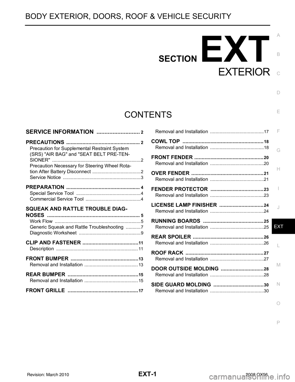
EXT-1
BODY EXTERIOR, DOORS, ROOF & VEHICLE SECURITY
C
DE
F
G H
I
J
L
M
SECTION EXT
A
B
EXT
N
O P
CONTENTS
EXTERIOR
SERVICE INFORMATION .. ..........................2
PRECAUTIONS .............................................. .....2
Precaution for Supplemental Restraint System
(SRS) "AIR BAG" and "SEAT BELT PRE-TEN-
SIONER" ............................................................. ......
2
Precaution Necessary for Steering Wheel Rota-
tion After Battery Disconnect ............................... ......
2
Service Notice ...........................................................3
PREPARATION ...................................................4
Special Service Tool ........................................... ......4
Commercial Service Tool ..........................................4
SQUEAK AND RATTLE TROUBLE DIAG-
NOSES ................................................................
5
Work Flow ........................................................... ......5
Generic Squeak and Rattle Troubleshooting ............7
Diagnostic Worksheet ...............................................9
CLIP AND FASTENER .......................................11
Description .......................................................... ....11
FRONT BUMPER ...............................................13
Removal and Installation .........................................13
REAR BUMPER ............................................. ....15
Removal and Installation .........................................15
FRONT GRILLE .................................................17
Removal and Installation ..................................... ....17
COWL TOP .......................................................18
Removal and Installation .........................................18
FRONT FENDER ...............................................20
Removal and Installation .........................................20
OVER FENDER .................................................21
Removal and Installation .........................................21
FENDER PROTECTOR ....................................23
Removal and Installation .........................................23
LICENSE LAMP FINISHER ..............................24
Removal and Installation .........................................24
RUNNING BOARDS .........................................25
Removal and Installation .........................................25
REAR SPOILER ................................................26
Removal and Installation .........................................26
ROOF RACK .....................................................27
Removal and Installation ..................................... ....27
DOOR OUTSIDE MOLDING .............................28
Removal and Installation .........................................28
SIDE GUARD MOLDING ..................................30
Removal and Installation ..................................... ....30
Revision: March 2010 2008 QX56