2008 INFINITI QX56 display
[x] Cancel search: displayPage 2362 of 4083
![INFINITI QX56 2008 Factory Service Manual INSUFFICIENT COOLINGHAC-109
< SYMPTOM DIAGNOSIS > [AUTOMATIC AIR CONDITIONER]
C
D
E
F
G H
J
K L
M A
B
HAC
N
O P
INSUFFICIENT COOLING
Component Function CheckINFOID:0000000001679830
SYMPTOM: Insufficie INFINITI QX56 2008 Factory Service Manual INSUFFICIENT COOLINGHAC-109
< SYMPTOM DIAGNOSIS > [AUTOMATIC AIR CONDITIONER]
C
D
E
F
G H
J
K L
M A
B
HAC
N
O P
INSUFFICIENT COOLING
Component Function CheckINFOID:0000000001679830
SYMPTOM: Insufficie](/manual-img/42/57030/w960_57030-2361.png)
INSUFFICIENT COOLINGHAC-109
< SYMPTOM DIAGNOSIS > [AUTOMATIC AIR CONDITIONER]
C
D
E
F
G H
J
K L
M A
B
HAC
N
O P
INSUFFICIENT COOLING
Component Function CheckINFOID:0000000001679830
SYMPTOM: Insufficient cooling
INSPECTION FLOW
1.CONFIRM SYMPTOM BY PERFORMING OPERAT IONAL CHECK - TEMPERATURE DECREASE
1. Press the AUTO switch.
2. Turn temperature control dial (driver) counterclockwise until 18 °C (60° F) is displayed.
3. Check for cold air at discharge air outlets.
Can the symptom be duplicated?
YES >> GO TO 3.
NO >> GO TO 2.
2.CHECK FOR ANY SYMPTOMS
Perform a complete operational check for any symptoms. Refer to HAC-4, "
Operational Check (Front)".
Does another symptom exist?
YES >> Refer to HAC-108, "SymptomMatrixChart".
NO >> System OK.
3.CHECK FOR SERVICE BULLETINS
Check for any service bulletins.
>> GO TO 4.
4.PERFORM SELF-DIAGNOSIS
Perform self-diagnosis Refer to HAC-22, "
A/C Auto Amp. Self-Diagnosis".
Is the inspection result normal?
YES >> GO TO 5.
NO >> Refer to HAC-23, "
A/C System Self-Diagnosis Code Chart".
5.CHECK DRIVE BELTS
Check compressor belt tension. Refer to EM-13, "
Checking Drive Belts".
Is the inspection result normal?
OK >> GO TO 6.
NG >> Adjust or replace compressor belt. Refer to EM-13, "
Removal and Installation".
6.CHECK AIR MIX DOOR OPERATION
Check and verify air mix door mechanism for smooth operation. Refer to HAC-31, "
Air Mix Door Motor Compo-
nent Function Check".
Does air mix door operate correctly?
YES >> GO TO 7.
NO >> Check air mix door motor circuit. Refer to HAC-32, "
Air Mix Door Motor (Driver) Diagnosis Proce-
dure" or HAC-35, "Air Mix Door Motor (Passenger) Diagnosis Procedure".
7.CHECK COOLING FAN MOTOR OPERATION
Check and verify cooling fan moto r for smooth operation. Refer to EC-395, "
Component Inspection".
Does cooling fan motor operate correctly?
YES >> GO TO 8.
NO >> Check cooling fan motor. Refer to EC-395, "
Diagnosis Procedure".
8.CHECK WATER VALVE OPERATION
Check and verify water valve for smooth operation. Refer to HAC-76, "
Description".
Does water valve operate correctly?
YES >> GO TO 9.
Revision: March 2010 2008 QX56
Page 2370 of 4083
![INFINITI QX56 2008 Factory Service Manual INSUFFICIENT HEATINGHAC-117
< SYMPTOM DIAGNOSIS > [AUTOMATIC AIR CONDITIONER]
C
D
E
F
G H
J
K L
M A
B
HAC
N
O P
INSUFFICIENT HEATING
Component Function CheckINFOID:0000000001679835
SYMPTOM: Insufficie INFINITI QX56 2008 Factory Service Manual INSUFFICIENT HEATINGHAC-117
< SYMPTOM DIAGNOSIS > [AUTOMATIC AIR CONDITIONER]
C
D
E
F
G H
J
K L
M A
B
HAC
N
O P
INSUFFICIENT HEATING
Component Function CheckINFOID:0000000001679835
SYMPTOM: Insufficie](/manual-img/42/57030/w960_57030-2369.png)
INSUFFICIENT HEATINGHAC-117
< SYMPTOM DIAGNOSIS > [AUTOMATIC AIR CONDITIONER]
C
D
E
F
G H
J
K L
M A
B
HAC
N
O P
INSUFFICIENT HEATING
Component Function CheckINFOID:0000000001679835
SYMPTOM: Insufficient heating
INSPECTION FLOW
1.CONFIRM SYMPTOM BY PERFORMING OPERAT IONAL CHECK - TEMPERATURE INCREASE
1. Press the AUTO switch.
2. Turn the temperature control dial (driver) clockwise until 32 °C (90 °F) is displayed.
3. Check for hot air at discharge air outlets.
Can this symptom be duplicated?
YES >> GO TO 2.
NO >> Perform complete system operational check. Refer to HAC-4, "
Operational Check (Front)".
2.CHECK FOR SERVICE BULLETINS
Check for any service bulletins.
>> GO TO 3.
3.PERFORM SELF-DIAGNOSIS
Perform self-diagnosis. Refer to HAC-22, "
A/C Auto Amp. Self-Diagnosis".
Is the inspection results normal?
YES >> GO TO 4.
NO >> Refer to HAC-23, "
A/C System Self-Diagnosis Code Chart".
4.CHECK ENGINE COOLING SYSTEM
1. Check for proper engine coolant level. Refer to CO-10, "
Inspection".
2. Check hoses for leaks or kinks.
3. Check radiator cap. Refer to CO-10, "
Inspection".
4. Check for air in cooling system.
>> GO TO 5.
5.CHECK AIR MIX DOOR OPERATION
Check the operation of the air mix door.
Is the inspection result normal?
YES >> GO TO 6.
NO >> Check the air mix door motor circuit. Refer to HAC-31, "
Air Mix Door Motor Component Function
Check".
6.CHECK AIR DUCTS
Check for disconnected or leaking air ducts.
Is the inspection result normal?
YES >> GO TO 7.
NO >> Repair all disconnected or leaking air ducts.
7.CHECK HEATER HOSE TEMPERATURES
1. Start engine and warm it up to normal operating temperature.
2. Touch both the inlet and outlet heater hoses.
Is the inspection result normal?
YES >> Hot inlet hose and a warm outlet hose: GO TO 8.
NO >> • Inlet hose cold: GO TO 11. • Both hoses warm: GO TO 9.
8.CHECK ENGINE COOLANT SYSTEM
Check engine control temperature sensor. Refer to EC-126, "
Component Inspection".
Revision: March 2010 2008 QX56
Page 2376 of 4083
![INFINITI QX56 2008 Factory Service Manual PRECAUTIONSHAC-123
< PRECAUTION > [AUTOMATIC AIR CONDITIONER]
C
D
E
F
G H
J
K L
M A
B
HAC
N
O P
If a refrigerant other than pure HFC-134a (R-134a) is identified in a vehicle, your options are:
• Exp INFINITI QX56 2008 Factory Service Manual PRECAUTIONSHAC-123
< PRECAUTION > [AUTOMATIC AIR CONDITIONER]
C
D
E
F
G H
J
K L
M A
B
HAC
N
O P
If a refrigerant other than pure HFC-134a (R-134a) is identified in a vehicle, your options are:
• Exp](/manual-img/42/57030/w960_57030-2375.png)
PRECAUTIONSHAC-123
< PRECAUTION > [AUTOMATIC AIR CONDITIONER]
C
D
E
F
G H
J
K L
M A
B
HAC
N
O P
If a refrigerant other than pure HFC-134a (R-134a) is identified in a vehicle, your options are:
• Explain to the customer that environmental regulations prohibit the release of contaminated refrigerant into
the atmosphere.
• Explain that recovery of the contaminated refri gerant could damage your service equipment and refrigerant
supply.
• Suggest the customer return the vehicle to the locati on of previous service where the contamination may
have occurred.
• If you choose to perform the repair, recover the refrigerant using only dedicated equipment and contain-
ers. Do not recover contaminated refrig erant into your existing service equipment. If your facility does
not have dedicated recovery equipment, you may contact a local refrigerant product retailer for available ser-
vice. This refrigerant must be disposed of in accordance with all federal and local regulations. In addition,
replacement of all refrigerant system components on the vehicle is recommended.
• If the vehicle is within the warranty period, the air conditioner warranty is void. Please contact NISSAN Cus-
tomer Affairs for further assistance.
Precaution for Service EquipmentINFOID:0000000001679840
MANIFOLD GAUGE SET
Be certain that the gauge face indicates R-134a or 134a. Make sure
the gauge set has 1/2 ″-16 ACME threaded connections for service
hoses. Confirm the set has been used only with refrigerant HFC-
134a (R-134a) along with specified oil.
SERVICE HOSES
Be certain that the service hoses display the markings described
(colored hose with black stripe). All hoses must include positive shut-
off devices (either manual or aut omatic) near the end of the hoses
opposite the manifold gauge.
SERVICE COUPLERS
Never attempt to connect HFC-134a (R-134a) service couplers to a
CFC-12 (R-12) A/C system. The HFC-134a (R-134a) couplers will
not properly connect to the CFC-12 (R-12) system. However, if an
improper connection is attempted, discharging and contamination
may occur.
SHA533D
RHA272D
Shut-off valve rotati on A/C service valve
Clockwise Open
Counterclockwise Close
RHA273D
Revision: March 2010 2008 QX56
Page 2394 of 4083

DIAGNOSIS SYSTEM (BCM)INL-11
< FUNCTION DIAGNOSIS >
C
DE
F
G H
I
J
K
M A
B
INL
N
O P
DIAGNOSIS SYSTEM (BCM)
COMMON ITEM
COMMON ITEM : CONSULT-III FunctionINFOID:0000000001601383
CONSULT-III can display each diagnostic item using the diagnostic test modes shown following.
INT LAMP
INT LAMP : CONSULT-III FunctionINFOID:0000000001601384
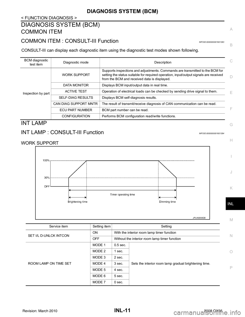
WORK SUPPORT
BCM diagnostic test item Diagnostic mode
Description
Inspection by part WORK SUPPORT
Supports inspections and adjustments. Commands are transmitted to the BCM for
setting the status suitable for required operation, input/output signals are received
from the BCM and received data is displayed.
DATA MONITOR Displays BCM input/output data in real time. ACTIVE TEST Operation of electrical loads can be checked by sending drive signal to them.
SELF-DIAG RESULTS Displays BCM self-diagnosis results.
CAN DIAG SUPPORT MNTR The result of transmit/receive diagnosis of CAN communication can be read. ECU PART NUMBER BCM part number can be read.
CONFIGURATION Performs BCM configuration read/write functions.
JPLIA0093GB
Service item Setting item Setting
SET I/L D-UNLCK INTCON ON With the interior room lamp timer function
OFF Without the interior room lamp timer function
ROOM LAMP ON TIME SET MODE 1 0.5 sec.
Sets the interior room lamp gradual brightening time.
MODE 2 1 sec.
MODE 3 2 sec.
MODE 4 3 sec.
MODE 5 4 sec.
MODE 6 5 sec.
MODE 7 0 sec.
Revision: March 2010
2008 QX56
Page 2465 of 4083

INT-16
< ON-VEHICLE REPAIR >
FLOOR TRIM
FLOOR TRIM
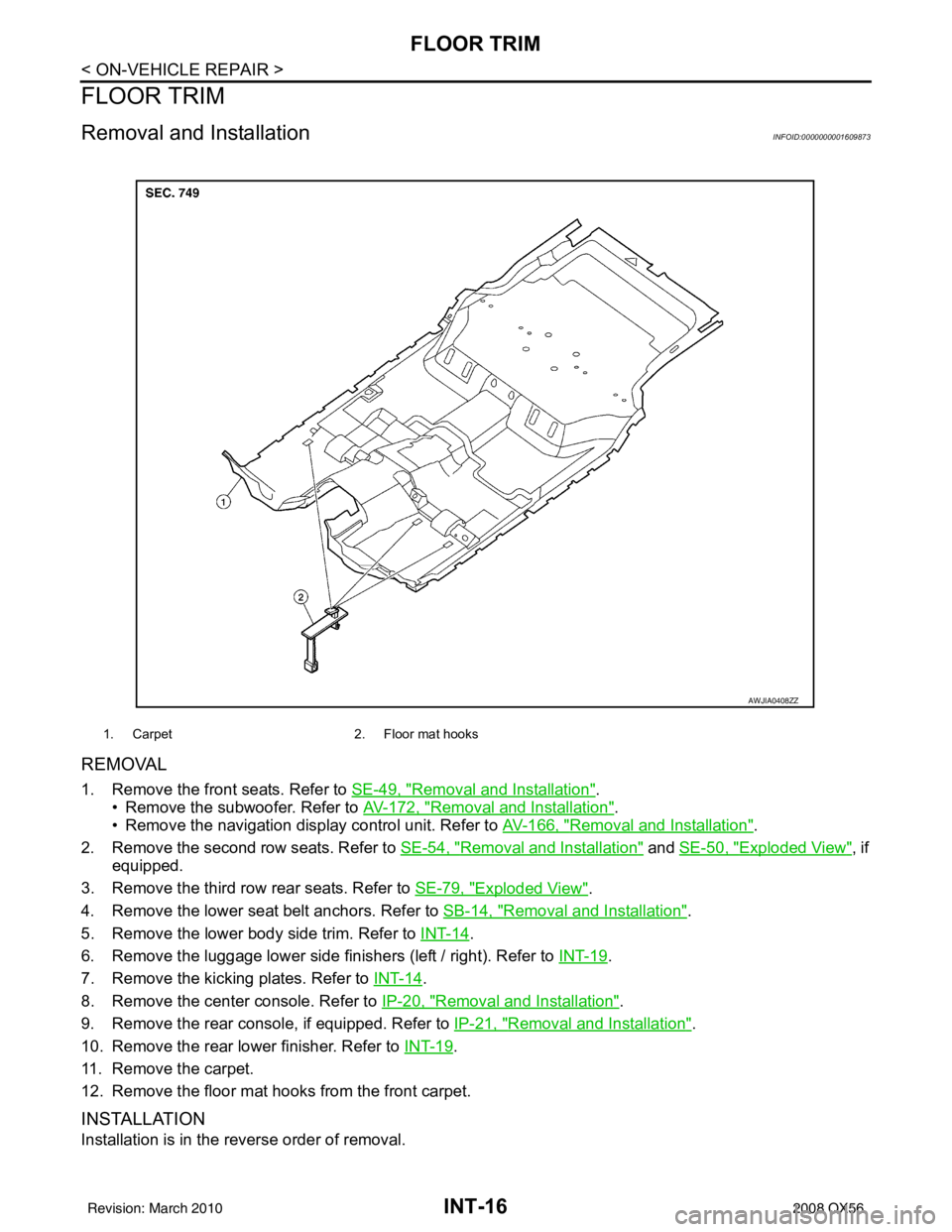
Removal and InstallationINFOID:0000000001609873
REMOVAL
1. Remove the front seats. Refer to SE-49, "Removal and Installation".
• Remove the subwoofer. Refer to AV-172, "
Removal and Installation".
• Remove the navigation display control unit. Refer to AV-166, "
Removal and Installation".
2. Remove the second row seats. Refer to SE-54, "
Removal and Installation" and SE-50, "Exploded View", if
equipped.
3. Remove the third row rear seats. Refer to SE-79, "
Exploded View".
4. Remove the lower seat belt anchors. Refer to SB-14, "
Removal and Installation".
5. Remove the lower body side trim. Refer to INT-14
.
6. Remove the luggage lower side finishers (left / right). Refer to INT-19
.
7. Remove the kicking plates. Refer to INT-14
.
8. Remove the center console. Refer to IP-20, "
Removal and Installation".
9. Remove the rear console, if equipped. Refer to IP-21, "
Removal and Installation".
10. Remove the rear lower finisher. Refer to INT-19
.
11. Remove the carpet.
12. Remove the floor mat hooks from the front carpet.
INSTALLATION
Installation is in the reverse order of removal.
1. Carpet 2. Floor mat hooks
AWJIA0408ZZ
Revision: March 2010 2008 QX56
Page 2467 of 4083

INT-18
< ON-VEHICLE REPAIR >
HEADLINING
CAUTION:
Disconnect both terminals from battery in advance.
REMOVAL
1. Remove the body side trim. Refer to INT-14.
2. Remove the luggage floor trim. Refer to INT-19
.
3. Remove the sunvisor assemblies.
4. Remove the sunvisor clips.
5. Remove the sunroof welt.
6. Remove the front roof console. • Disconnect the harnesses.
7. Remove the rear roof console. • Disconnect the harnesses.
8. Remove the assist grips.
9. Remove the lamp assembly and the rear roof finisher. • Disconnect the harness.
10. Remove the headlining. • Remove the clips from the rear of headlining.
• Disconnect the harnesses.
11. Remove the rear air control. • Disconnect the harness.
12. Remove the rear audio control assembly. • Disconnect the harness.
13. Remove the lamp assemblies. • Disconnect the harnesses.
14. Remove the air vents.
15. Remove the front roof console bracket.
16. Remove the rear roof console front bracket.
17. Remove the assist grip brackets from roof.
INSTALLATION
Installation is in the reverse order of removal.
10. Cap RH 11. Sunvisor assembly RH12. Rear roof console bracket
13. Rear storage bin or DVD display 14. Rear air control 15. Rear audio control assembly
16. Rear roof console 17. Rear roof console finisher18. Rear storage bin
19. Air vent 20. Lamp assembly21. Plastic clip
22. Rear lamp lens 23. Rear lamp24. Rear roof finisher
25. Plastic clip 26. Metal clip Vehicle front
Revision: March 2010 2008 QX56
Page 2482 of 4083

IP-12
< ON-VEHICLE REPAIR >
INSTRUMENT PANEL ASSEMBLY
Removal and Installation
INFOID:0000000001602122
REMOVAL
CAUTION:
Disconnect both the negative and po sitive battery terminals in advance.
1. Disconnect both negative and positive termi nals, then wait at least 3 minutes.
2. Remove front center console. Refer to IP-20, "
Removal and Installation".
3. Remove steering column assembly. Refer to ST-20, "
Removal and Installation".
4. Remove combination meter. Refer to MWI-76, "
Removal and Installation".
5. Remove instrument panel upper cover and disconnect rear sonar speaker (if equipped).
6. Remove cluster lid C. Refer to IP-15, "
Removal and Installation".
7. Remove display assembly. Refer to AV-164, "
Removal and Installation".
8. Remove instrument lower/upper panel RH and glove box. Refer to IP-17, "
Removal and Installation" and
IP-18, "
Removal and Installation".
9. Release the clips, disconnect the optical sensor harness and remove defroster grille.
10. Release the clips, disconnect the connecto rs and remove RH, LH, and center speakers.
11. Remove RH/LH front pillar finishers. Refer to INT-14, "
Removal and Installation".
12. Remove the passenger air bag module nuts and disconnect the connectors. Refer to SR-10, "
Removal
and Installation".
13. Disconnect remaining optional equipment connectors (if equipped).
14. Remove instrument panel and pad assembly screws.
15. Release instrument panel and pad assembly lifting rearward away from steering member, then carefully remove through front door opening.
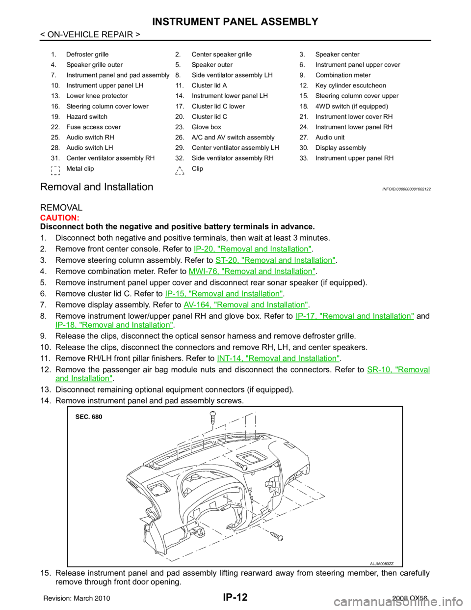
1. Defroster grille 2. Center speaker grille3. Speaker center
4. Speaker grille outer 5. Speaker outer6. Instrument panel upper cover
7. Instrument panel and pad assembly 8. Side ventilator assembly LH 9. Combination meter
10. Instrument upper panel LH 11. Cluster lid A 12. Key cylinder escutcheon
13. Lower knee protector 14. Instrument lower panel LH 15. Steering column cover upper
16. Steering column cover lower 17. Cluster lid C lower 18. 4WD switch (if equipped)
19. Hazard switch 20. Cluster lid C21. Instrument lower cover RH
22. Fuse access cover 23. Glove box 24. Instrument lower panel RH
25. Audio switch RH 26. A/C and AV switch assembly 27. Audio unit
28. Audio switch LH 29. Center ventilator assembly LH 30. Display assembly
31. Center ventilator assembly RH 32. Side ventilator assembly RH 33. Instrument upper panel RH Metal clip Clip
ALJIA0083ZZ
Revision: March 2010 2008 QX56
Page 2503 of 4083
![INFINITI QX56 2008 Factory Service Manual LAN-8
< FUNCTION DIAGNOSIS >[CAN FUNDAMENTAL]
TROUBLE DIAGNOSIS
Example: Data link connector branch line open circuit
NOTE:
• When data link connector branch line is open, transmission and reception INFINITI QX56 2008 Factory Service Manual LAN-8
< FUNCTION DIAGNOSIS >[CAN FUNDAMENTAL]
TROUBLE DIAGNOSIS
Example: Data link connector branch line open circuit
NOTE:
• When data link connector branch line is open, transmission and reception](/manual-img/42/57030/w960_57030-2502.png)
LAN-8
< FUNCTION DIAGNOSIS >[CAN FUNDAMENTAL]
TROUBLE DIAGNOSIS
Example: Data link connector branch line open circuit
NOTE:
• When data link connector branch line is open, transmission and reception of CAN communication signals
are not affected. Therefore, no symptoms occur. However, be sure to repair malfunctioning circuit.
• When data link connector branch line is open, “ECU list” displayed on the CONSULT-III “CAN DIAG SUP- PORT MNTR” may be the same as when the CAN communication line has short-circuit. However, symp-
toms differ depending on the case. See below chart for the differences.
EPS control unit Normal operation.
Combination meter • Shift position indicator and OD OFF indicator turn OFF.
• Warning lamps turn ON.
ABS actuator and electric unit (control unit) Normal operation.
TCM No impact on operation.
IPDM E/R Normal operation.
Unit name
Symptom
SKIB8739E
Unit nameSymptom
ECM
Normal operation.
BCM
EPS control unit
Combination meter
ABS actuator and electric unit (control unit)
TCM
IPDM E/R
“ECU list” on the “CAN DIAG SUPPORT MNTR”(CONSULT-III) Difference of symptom
Data link connector branch line open circuit All Diag on CAN units are not
indicated.Normal operation.
CAN-H, CAN-L harness short-circuit Most of the units which are connected to the CAN
communication system enter fail-safe mode or are
deactivated.
Revision: March 2010
2008 QX56