2008 INFINITI QX56 battery voltage
[x] Cancel search: battery voltagePage 2342 of 4083
![INFINITI QX56 2008 Factory Service Manual POWER SUPPLY AND GROUND CIRCUIT FOR CONTROLLER
HAC-89
< COMPONENT DIAGNOSIS > [AUTOMATIC AIR CONDITIONER]
C
D
E
F
G H
J
K L
M A
B
HAC
N
O P
Check main power supply and ground circuit. Refer to HAC-89, INFINITI QX56 2008 Factory Service Manual POWER SUPPLY AND GROUND CIRCUIT FOR CONTROLLER
HAC-89
< COMPONENT DIAGNOSIS > [AUTOMATIC AIR CONDITIONER]
C
D
E
F
G H
J
K L
M A
B
HAC
N
O P
Check main power supply and ground circuit. Refer to HAC-89,](/manual-img/42/57030/w960_57030-2341.png)
POWER SUPPLY AND GROUND CIRCUIT FOR CONTROLLER
HAC-89
< COMPONENT DIAGNOSIS > [AUTOMATIC AIR CONDITIONER]
C
D
E
F
G H
J
K L
M A
B
HAC
N
O P
Check main power supply and ground circuit. Refer to HAC-89, "A/C Auto Amp Power and Ground Diagnosis
Procedure".
Is the inspection result normal?
YES >> System OK.
NO >> Replace A/C auto amp. Refer to VTL-7, "
Removal and Installation".
A/C Auto Amp Power and Ground Diagnosis ProcedureINFOID:0000000001679826
DIAGNOSTIC PROCEDURE FOR A/C SYSTEM
SYMPTOM: A/C system does not come on.
1. CHECK POWER SUPPLY CIRCUITS FOR A/C AUTO AMP.
1. Disconnect A/C auto amp. connectors.
2. Check voltage between A/C auto amp. harness connector M49 (B) terminal 15 and M50 (A) terminal 27, and ground.
Is the inspection result normal?
YES >> GO TO 2.
NO >> Check 10A fuses [Nos. 8 and 19, located in the fuse block (J/B)]. Refer to PG-70, "
Terminal
Arrangement".
• If fuses are OK, check harness for open circuit. Repair or replace as necessary.
• If fuses are NG, replace fuse and check harness fo r short circuit. Repair or replace as neces-
sary.
2. CHECK GROUND CIRCUIT FOR A/C AUTO AMP.
1. Turn ignition switch OFF.
2. Check continuity between A/C auto amp. harness connector M50 terminal 36 and ground.
Is the inspection result normal?
OK >> Replace A/C auto amp. Refer to VTL-7, "Removal and
Installation".
NG >> Repair harness or connector.
AWIIA0212GB
Terminals Ignition switch position
(+)
(-) OFF ACC ON
A/C auto
amp. con- nector Te r m i n a l N o .
M49 15 GroundApprox. 0V Approx. 0V
Battery
voltage
M50 27 Battery
voltage Battery
voltage Battery
voltage
AWIIA0215ZZ
36 - Ground : Continuity should exist.
AWIIA0214ZZ
Revision: March 2010 2008 QX56
Page 2343 of 4083
![INFINITI QX56 2008 Factory Service Manual HAC-90
< ECU DIAGNOSIS >[AUTOMATIC AIR CONDITIONER]
AIR CONDITIONER CONTROL
ECU DIAGNOSIS
AIR CONDITIONER CONTROL
A/C Auto Amp. Terminals Reference ValuesINFOID:0000000001679827
Measure voltage betwee INFINITI QX56 2008 Factory Service Manual HAC-90
< ECU DIAGNOSIS >[AUTOMATIC AIR CONDITIONER]
AIR CONDITIONER CONTROL
ECU DIAGNOSIS
AIR CONDITIONER CONTROL
A/C Auto Amp. Terminals Reference ValuesINFOID:0000000001679827
Measure voltage betwee](/manual-img/42/57030/w960_57030-2342.png)
HAC-90
< ECU DIAGNOSIS >[AUTOMATIC AIR CONDITIONER]
AIR CONDITIONER CONTROL
ECU DIAGNOSIS
AIR CONDITIONER CONTROL
A/C Auto Amp. Terminals Reference ValuesINFOID:0000000001679827
Measure voltage between each terminal and ground by following
Terminals and Reference Value for A/C auto amp. (1).
A/C AUTO AMP. HARNESS CONNECTOR TERMINAL LAYOUT
TERMINALS AND REFERENCE VALUES FOR A/C AUTO AMP.
AWIIA0170ZZ
AWIIA0568ZZ
Te r m i n a l
No. Wire
color Item
Ignition
switch Condition
Voltage (V)
(Approx.)
1 G/O Optical sensor (driver) ON- 0 - 5V
2 L Air mix door motor (passe nger) ON-Battery voltage
3 P V ref ACTR (ground) ON- 5V
4 W/R Compressor ON signal ON A/C switch OFF
5V
ON A/C switch ON 0V
5 L/R Fan ON signal ON Blower switch OFF
5V
ON Blower switch ON 0V
6 SB Air mix door motor (driver) feedback ON -0 - 5V
7 GR Mode door motor feedback ON- 0 - 5V
8 R/L Illumination + ON Park lamps ONBattery voltage
9 BR Illumination - - Park lamps ON
10 LG/B Defroster door motor feedback ON -0 - 5V
11 L/B Intake sensor ON- 0 - 5V
12 G/Y Variable blower control (rear) ON- 0 - 5V
PIIA2344E
Revision: March 2010 2008 QX56
Page 2344 of 4083
![INFINITI QX56 2008 Factory Service Manual AIR CONDITIONER CONTROLHAC-91
< ECU DIAGNOSIS > [AUTOMATIC AIR CONDITIONER]
C
D
E
F
G H
J
K L
M A
B
HAC
N
O P
13 G/R Variable blower control (front) ONBlower speed (low)
1.7V
Blower speed (high) 4.5V
INFINITI QX56 2008 Factory Service Manual AIR CONDITIONER CONTROLHAC-91
< ECU DIAGNOSIS > [AUTOMATIC AIR CONDITIONER]
C
D
E
F
G H
J
K L
M A
B
HAC
N
O P
13 G/R Variable blower control (front) ONBlower speed (low)
1.7V
Blower speed (high) 4.5V](/manual-img/42/57030/w960_57030-2343.png)
AIR CONDITIONER CONTROLHAC-91
< ECU DIAGNOSIS > [AUTOMATIC AIR CONDITIONER]
C
D
E
F
G H
J
K L
M A
B
HAC
N
O P
13 G/R Variable blower control (front) ONBlower speed (low)
1.7V
Blower speed (high) 4.5V
14 G/W Air mix door motor (passenger) CW ON Clockwise rotation Battery voltage
15 Y/G Power supply for IGN ON- Battery voltage
17 W/G Air mix door motor (driver) CW ON Clockwise rotationBattery voltage
18 G Air mix door motor (driver) CCW ON Co unterclockwise rotationBattery voltage
19 BR/W Mode door motor CW (front) ON Clockwise rotationBattery voltage
20 P/L Mode door motor CCW ON Counterclockwise rotationBattery voltage
21 G/B Intake door motor CCW ON Counterclockwise rotationBattery voltage
22 O Intake door motor CW ON Clockwise rotationBattery voltage
23 LG Defroster door motor CW ON Clockwise rotationBattery voltage
24 P/B Defroster door motor CCW ON Counterclockwise rotationBattery voltage
25 P Ambient sensor ON- 0 - 5V
26 V/R Sensor ground ON- 0V
27 Y/R Power supply for BAT -- Battery voltage
28 Y V ref ACTR (5V) ON- 0 - 5V
29 R/W Air mix door motor (passenger) feed-
back
ON
- 0 - 5V
30 R/Y Mode door motor (Rear) feedback ON -0 - 5V
31 BR/Y In-vehicle sensor motor (+) ON- Battery voltage
32 LG/R In-vehicle sensor signal ON- 0 - 5V
33 R/Y Air mix door motor (Rear) feedback ON -0 - 5V
36 B Ground -- 0V
40 P CAN-L ON- 0 - 5V
41 L CAN-H ON- 0 - 5V
42 W/V Optical sensor (passenger) ON- 0 - 5V
43 GR/R Mode door motor (Rear) CW ONClockwise rotation Battery voltage
44 L/Y Mode door motor (Rear) CCW ON Coun terclockwise rotationBattery voltage
45 Y/L Water valve ONWater valve open
Battery voltage
Water valve closed 0V
46 W/G Water valve ONWater valve open
0V
Water valve closed Battery voltage
47 O LIN BUS (rear) ON- Battery voltage
48 O LIN BUS (front) ON- Battery voltage
49 GR/R Air mix door motor (Rear) CW ONClockwise rotation Battery voltage
50 L/Y Air mix door motor (Rear) CCW ON Co unterclockwise rotationBattery voltage
Te r m i n a l
No. Wire
color ItemIgnition
switch Condition Voltage (V)
(Approx.)
Revision: March 2010 2008 QX56
Page 2398 of 4083

INTERIOR ROOM LAMP POWER SUPPLY CIRCUIT
INL-15
< COMPONENT DIAGNOSIS >
C
D E
F
G H
I
J
K
M A
B
INL
N
O P
INTERIOR ROOM LAMP POWER SUPPLY CIRCUIT
DescriptionINFOID:0000000001601387
Provides the battery saver output/power supply. Also cu ts the power supply when the interior room lamp bat-
tery saver is activating.
Component Function CheckINFOID:0000000001601388
1.CHECK BATTERY SAVER OUTPUT /POWER SUPPLY FUNCTION
CONSULT-III
1. Turn ignition switch ON.
2. Turn each interior room lamp ON.
- Front room/map lamp assembly
- Vanity lamps
- Personal lamp 2nd row
- Personal lamp 3rd row
- Cargo lamp
3. Open the driver door to turn ON the step lamps, foot lamps and puddle lamps.
- Front step lamps
- Rear step lamps
- Foot lamps
- Puddle lamps
- Ignition keyhole Illumination
4. Select “BATTERY SAVER” of BCM (BATTERY SAVER) active test item.
5. While operating the test item, check that each interior room lamp turns ON/OFF.
Is the inspection result normal?
YES >> Battery saver output/power supply circuit is normal.
NO >> Refer to INL-15, "
Diagnosis Procedure".
Diagnosis ProcedureINFOID:0000000001601389
1.CHECK BATTERY SAVER OUTPUT/POWER SUPPLY OUTPUT
CONSULT-III
1. Turn ignition switch ON.
2. Select “BATTERY SAVER” of BCM (BATTERY SAVER) active
test item.
3. While operating the test item, check voltage between BCM con-
nector M20 terminal 56 and ground.
Is the inspection result normal?
YES >> GO TO 2
NO >> Replace BCM. Refer to BCS-55, "
Removal and Installation".
2.CHECK BATTERY SAVER OUTPUT/P OWER SUPPLY OPEN CIRCUIT
1. Turn ignition switch OFF.
2. Disconnect the following connectors.
-BCM M20
- Ignition keyhole illumination OFF : Interior room lamps OFF
ON : Interior room lamps ON
(+)
(-)Te s t i t e m
Voltag e
Connector Terminal BATTERY SAVER
M20 56 Ground OFF
0V
ON Battery voltage
ALLIA0408GB
Revision: March 2010 2008 QX56
Page 2400 of 4083

INTERIOR ROOM LAMP CONTROL CIRCUITINL-17
< COMPONENT DIAGNOSIS >
C
DE
F
G H
I
J
K
M A
B
INL
N
O P
INTERIOR ROOM LAMP CONTROL CIRCUIT
DescriptionINFOID:0000000001601390
Controls the following interior room lamps (ground side) by PWM signal
• Puddle lamps
• Front room/map lamp assembly
• Personal lamp 2nd row
• Personal lamp 3rd row
NOTE:
PWM signal control period is approximately 250 Hz (in the gradual brightening/dimming).
Component Function CheckINFOID:0000000001601391
CAUTION:
Before performing the diagnosis, check that the following is normal.
• Battery saver output/power supply
• Front room/map lamp bulbs
• Personal lamp bulbs
• Puddle lamp bulbs
1.CHECK INTERIOR ROOM LAMP CONTROL FUNCTION
CONSULT-III
1. Switch the front room/map lamp assembly switch to DOOR.
2. Turn ignition switch ON.
3. Select “INT LAMP” of BCM (INT LAMP) active test item.
4. While operating the test item, check that each interi or room lamp turns ON/OFF (gradual brightening/dim-
ming).
Is the inspection result normal?
YES >> Interior room lamp control circuit is normal.
NO >> Refer to INL-17, "
Diagnosis Procedure".
Diagnosis ProcedureINFOID:0000000001601392
1.CHECK INTERIOR ROOM LAMP CONTROL OUTPUT
CONSULT-III
1. Switch the front room/map lamp assembly switch to DOOR.
2. Turn ignition switch ON.
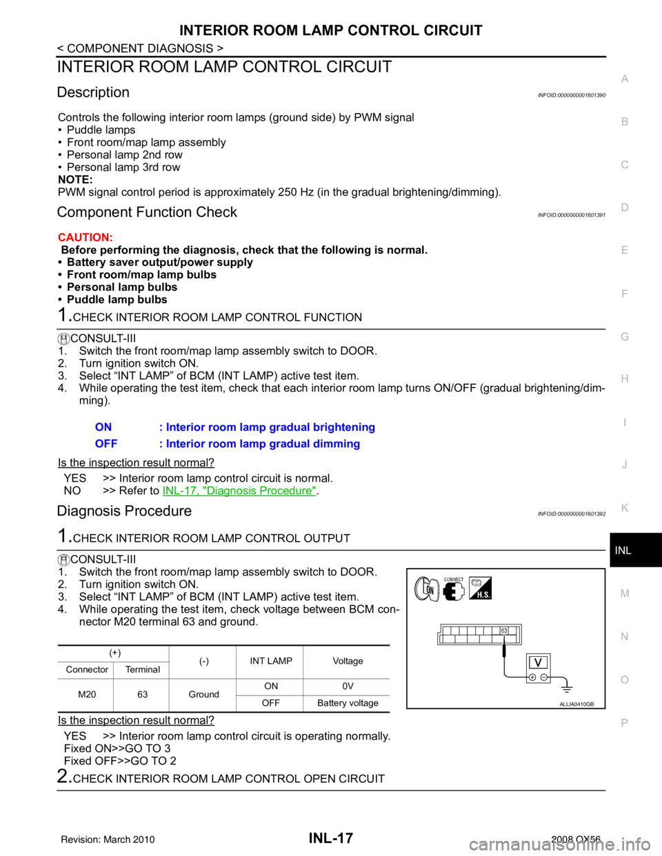
3. Select “INT LAMP” of BCM (INT LAMP) active test item.
4. While operating the test item, check voltage between BCM con- nector M20 terminal 63 and ground.
Is the inspection result normal?
YES >> Interior room lamp control circuit is operating normally.
Fixed ON>>GO TO 3
Fixed OFF>>GO TO 2
2.CHECK INTERIOR ROOM LAMP CONTROL OPEN CIRCUIT ON : Interior room lamp gradual brightening
OFF : Interior room lamp gradual dimming
(+)
(-) INT LAMP Voltage
Connector Terminal
M20 63 Ground ON
0V
OFF Battery voltage
ALLIA0410GB
Revision: March 2010 2008 QX56
Page 2402 of 4083

STEP LAMP CIRCUITINL-19
< COMPONENT DIAGNOSIS >
C
DE
F
G H
I
J
K
M A
B
INL
N
O P
STEP LAMP CIRCUIT
DescriptionINFOID:0000000001601393
Controls the front and rear step lamps and the foot lamps (ground side) to turn the lamps ON and OFF.
Component Function CheckINFOID:0000000001601394
CAUTION:
Before performing the diagnosis, check that the following is normal.
• Battery saver output/power supply
• Front step lamp bulbs
• Rear step lamp bulbs
• Foot lamp bulbs
1.CHECK STEP LAMP OPERATION
CONSULT-III
1. Turn ignition switch ON.
2. Select “STEP LAMP TEST” of BC M (INT LAMP) active test item.
3. While operating the test item, check that the front/rear step lamps and foot lamps turn ON/OFF.
Is the inspection result normal?
YES >> Step lamp circuit is normal.
NO >> Refer to INL-19, "
Diagnosis Procedure".
Diagnosis ProcedureINFOID:0000000001601395
1.CHECK STEP LAMP OUTPUT
CONSULT-III
1. Turn ignition switch ON.
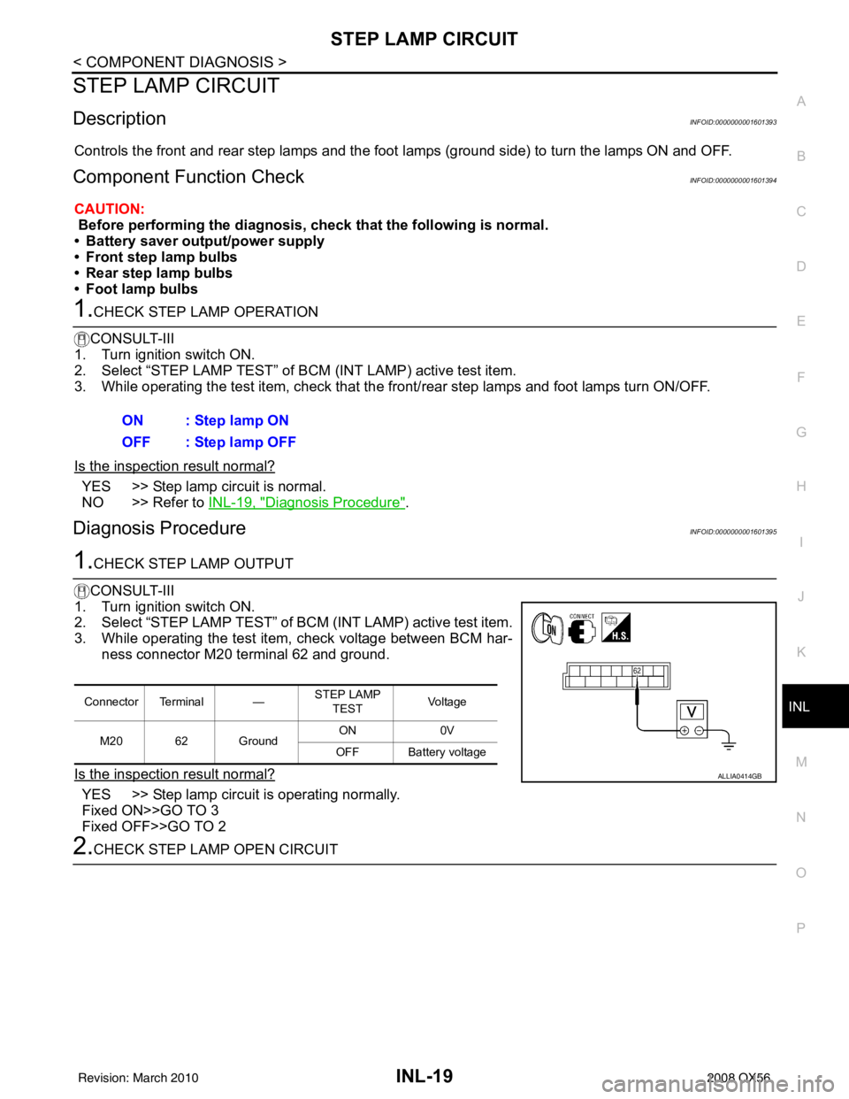
2. Select “STEP LAMP TEST” of BC M (INT LAMP) active test item.
3. While operating the test item, check voltage between BCM har- ness connector M20 terminal 62 and ground.
Is the inspection result normal?
YES >> Step lamp circuit is operating normally.
Fixed ON>>GO TO 3
Fixed OFF>>GO TO 2
2.CHECK STEP LAMP OPEN CIRCUIT ON : Step lamp ON
OFF : Step lamp OFF
Connector Terminal —
STEP LAMP
TEST Vo l ta g e
M20 62 Ground ON
0V
OFF Battery voltage
ALLIA0414GB
Revision: March 2010 2008 QX56
Page 2404 of 4083

CARGO LAMP CONTROL CIRCUITINL-21
< COMPONENT DIAGNOSIS >
C
DE
F
G H
I
J
K
M A
B
INL
N
O P
CARGO LAMP CONTROL CIRCUIT
DescriptionINFOID:0000000001601396
Controls the cargo lamp (ground side) to turn the cargo lamp ON and OFF.
Component Function CheckINFOID:0000000001601397
CAUTION:
Before performing the diagnosis, check that the following is normal.
• Battery saver output/power supply
• Cargo lamp bulb
1.CHECK CARGO LAMP OPERATION
CONSULT-III
1. Turn ignition switch ON.
2. Select “LUGGAGE LAMP TEST” of BCM (INT LAMP) active test item.
3. While operating the test item, chec k that cargo lamp turns ON/OFF.
Is the inspection result normal?
YES >> Cargo lamp circuit is normal.
NO >> Refer to INL-19, "
Diagnosis Procedure".
Diagnosis ProcedureINFOID:0000000001601398
1.CHECK CARGO LAMP OUTPUT
CONSULT-III
1. Turn ignition switch ON.
2. Select “LUGGAGE LAMP TEST” of BCM (INT LAMP) active test
item.
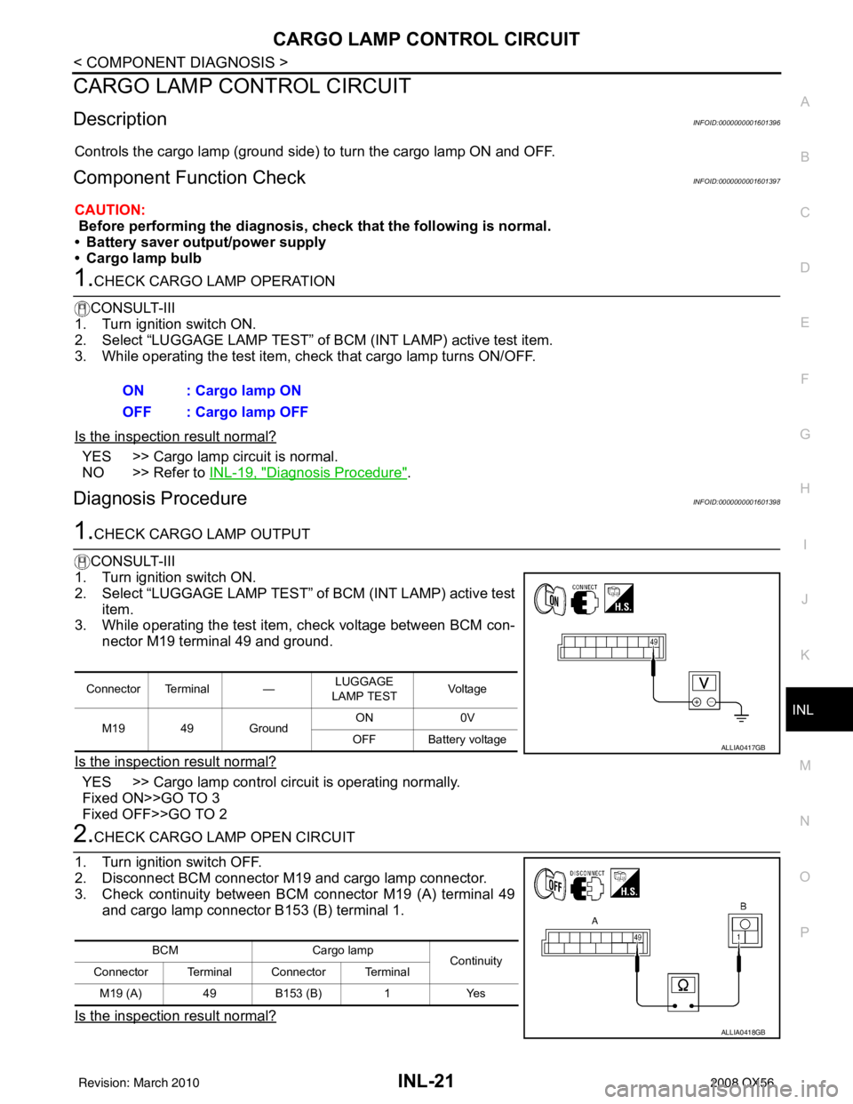
3. While operating the test item, check voltage between BCM con-
nector M19 terminal 49 and ground.
Is the inspection result normal?
YES >> Cargo lamp control circuit is operating normally.
Fixed ON>>GO TO 3
Fixed OFF>>GO TO 2
2.CHECK CARGO LAMP OPEN CIRCUIT
1. Turn ignition switch OFF.
2. Disconnect BCM connector M19 and cargo lamp connector.
3. Check continuity between BCM connector M19 (A) terminal 49 and cargo lamp connector B153 (B) terminal 1.
Is the inspection result normal?
ON : Cargo lamp ON
OFF : Cargo lamp OFF
Connector Terminal — LUGGAGE
LAMP TEST Vo l ta g e
M19 49 Ground ON
0V
OFF Battery voltage
ALLIA0417GB
BCM Cargo lamp
Continuity
Connector Terminal Connector Terminal
M19 (A) 49B153 (B) 1Yes
ALLIA0418GB
Revision: March 2010 2008 QX56
Page 2406 of 4083

IGNITION KEYHOLE ILLUMINATION CONTROL CIRCUIT
INL-23
< COMPONENT DIAGNOSIS >
C
D E
F
G H
I
J
K
M A
B
INL
N
O P
IGNITION KEYHOLE ILLUMI NATION CONTROL CIRCUIT
DescriptionINFOID:0000000001601399
Controls the ignition keyhole illumination (ground side) to turn the ignition keyhole illumination ON and OFF.
Component Function CheckINFOID:0000000001601400
CAUTION:
Before performing the diagnosis, check that the following is normal.
• Battery saver output/power supply circuit
• Ignition keyhole il lumination bulb
1.CHECK IGNITION KEYHOLE ILLUMINATION OPERATION
CONSULT-III
1. Turn the ignition switch ON.
2. Select “IGN ILLUM” of BCM (INT LAMP) active test item.
3. While operating the test item, check that the ignition keyhole illumination turns ON/OFF
Is the inspection result normal?
YES >> Ignition keyhole illumination circuit is normal.
NO >> Refer to INL-23, "
Diagnosis Procedure".
Diagnosis ProcedureINFOID:0000000001601401
1.CHECK IGNITION KEYHOLE OUTPUT
CONSULT-III
1. Turn ignition switch ON.
2. Select “IGN ILLUM” of BCM (INT LAMP) active test item.
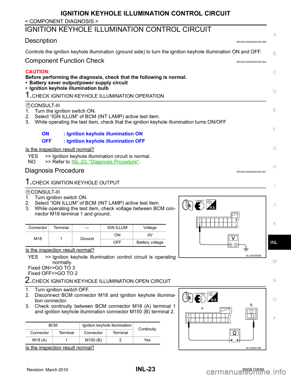
3. While operating the test item, check voltage between BCM con- nector M18 terminal 1 and ground.
Is the inspection result normal?
YES >> Ignition keyhole illumination control circuit is operating normally.
Fixed ON>>GO TO 3
Fixed OFF>>GO TO 2
2.CHECK IGNITION KEYHOLE I LLUMINATION OPEN CIRCUIT
1. Turn ignition switch OFF.
2. Disconnect BCM connector M18 and ignition keyhole illumina- tion connector.
3. Check continuity between BCM connector M18 (A) terminal 1 and ignition keyhole illumination connector M150 (B) terminal 2.
Is the inspection result normal?
ON : Ignition keyhole illumination ON
OFF : Ignition keyhole illumination OFF
Connector Terminal — IGN ILLUM Voltage
M18 1 Ground ON
0V
OFF Battery voltage
ALLIA0420GB
BCM Ignition keyhole illumination
Continuity
Connector Terminal Connector Terminal
M18 (A) 1 M150 (B) 2 Yes
ALLIA0421GB
Revision: March 2010 2008 QX56