2008 INFINITI QX56 battery voltage
[x] Cancel search: battery voltagePage 1960 of 4083
EXL-32
< COMPONENT DIAGNOSIS >
FRONT FOG LAMP CIRCUIT
FRONT FOG LAMP CIRCUIT
DescriptionINFOID:0000000001547131
The IPDM E/R (intelligent power distribution module engine room) controls the front fog lamp relay based on
inputs from the BCM via the CAN communication lines. When the front fog lamp relay is energized, power
flows from the front fog lamp relay in the IPDM E/R to the front fog lamps.
Component Function CheckINFOID:0000000001547132
1.CHECK FRONT FOG LAMP OPERATION
WITHOUT CONSULT-III
1. Activate IPDM E/R auto active test. Refer to PCS-12, "
Diagnosis Description".
2. Check that the front fog lamp is turned ON.
CONSULT-III
1. Select "EXTERNAL LAMP" of IPDM E/R active test item.
2. With operating the test items, Check that the front fog lamp is turned ON.
Is the front fog lamp turned ON?
YES >> Front fog lamp circuit is normal.
NO >> Refer to EXL-32, "
Diagnosis Procedure".
Diagnosis ProcedureINFOID:0000000001547133
1.CHECK FRONT FOG LAMP FUSE
1. Turn the ignition switch OFF.
2. Check that the following fuses are not open.
Is the fuse open?
YES >> Repair the harness and replace the fuse.
NO >> GO TO 2
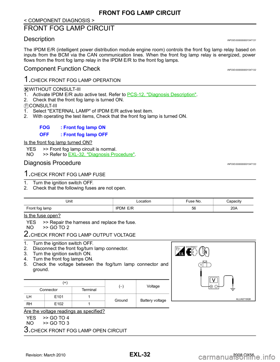
2.CHECK FRONT FOG LAMP OUTPUT VOLTAGE
1. Turn the ignition switch OFF.
2. Disconnect the front fog/turn lamp connector.
3. Turn the ignition switch ON.
4. Turn the front fog lamps ON.
5. Check the voltage between the fog/turn lamp connector and ground.
Are the voltage readings as specified?
YES >> GO TO 4
NO >> GO TO 3
3.CHECK FRONT FOG LAMP OPEN CIRCUIT FOG : Front fog lamp ON
OFF : Front fog lamp OFF
Unit
LocationFuse No.Capacity
Front fog lamp IPDM E/R5620A
(+)
(−)V olt a g e
Connector Terminal
LH E101 1
Ground Battery voltage
RH E102 1
ALLIA0719GB
Revision: March 2010 2008 QX56
Page 1962 of 4083
EXL-34
< COMPONENT DIAGNOSIS >
PARKING LAMP CIRCUIT
PARKING LAMP CIRCUIT
DescriptionINFOID:0000000001547134
The IPDM E/R (intelligent power distribution module engine room) controls the tail lamp relay based on inputs
from the BCM via the CAN communication lines. When the tail lamp relay is energized, power flows through
fuse 37, located in the IPDM E/R. Power then flows to the front and rear combination lamps.
Component Function CheckINFOID:0000000001547135
1.CHECK PARKING LAMP OPERATION
WITHOUT CONSULT-III
1. Activate IPDM E/R auto active test. Refer to PCS-12, "
Diagnosis Description".
2. Check that the parking lamp is turned ON.
CONSULT-III
1. Select "EXTERNAL LAMP" of IPDM E/R active test item.
2. With operating the test items, check that the parking lamp is turned ON.
Is the parking lamp turned ON?
YES >> Parking lamp circuit is normal.
NO >> Refer to EXL-34, "
Diagnosis Procedure".
Diagnosis ProcedureINFOID:0000000001547136
1.CHECK PARKING LAMP FUSES
1. Turn the ignition switch OFF.
2. Check that the following fuses are not open.
Is the fuse open?
YES >> Repair the harness and replace the fuse.
NO >> GO TO 2
2.CHECK TAIL LAMP RELAY OUTPUT (VOLTAGE)
1. Turn the ignition switch OFF.
2. Disconnect the front combination lamp connector, rear combination lamp connector and license plate
lamp connector.
3. Turn the ignition switch ON.
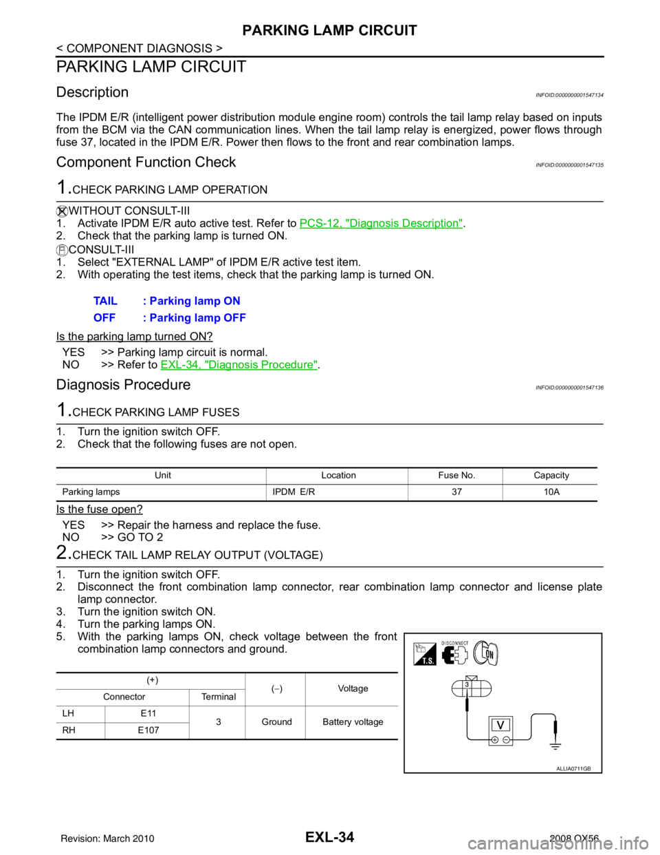
4. Turn the parking lamps ON.
5. With the parking lamps ON, check voltage between the front combination lamp connectors and ground.TAIL : Parking lamp ON
OFF : Parking lamp OFF
Unit
LocationFuse No.Capacity
Parking lamps IPDM E/R3710A
(+)
(−)Voltage
Connector Terminal
LH E11
3 Ground Battery voltage
RH E107
ALLIA0711GB
Revision: March 2010 2008 QX56
Page 1963 of 4083
PARKING LAMP CIRCUITEXL-35
< COMPONENT DIAGNOSIS >
C
DE
F
G H
I
J
K
M A
B
EXL
N
O P
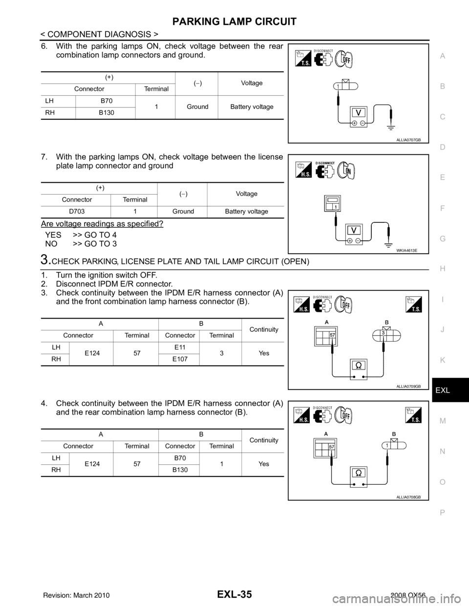
6. With the parking lamps ON, check voltage between the rear combination lamp connectors and ground.
7. With the parking lamps ON, check voltage between the license plate lamp connector and ground
Are voltage readings as specified?
YES >> GO TO 4
NO >> GO TO 3
3.CHECK PARKING, LICENSE PLATE AND TAIL LAMP CIRCUIT (OPEN)
1. Turn the ignition switch OFF.
2. Disconnect IPDM E/R connector.
3. Check continuity between the IPDM E/R harness connector (A) and the front combination lamp harness connector (B).
4. Check continuity between the IPDM E/R harness connector (A) and the rear combination lamp harness connector (B).
(+) (−)Voltage
Connector Terminal
LH B70 1 Ground Battery voltage
RH B130
ALLIA0707GB
(+) (−)V olt a g e
Connector Terminal
D703 1Ground Battery voltage
WKIA4613E
AB
Continuity
Connector Terminal Connector Terminal
LH E124 57E11
3Yes
RH E107
ALLIA0709GB
AB
Continuity
Connector Terminal Connector Terminal
LH E124 57B70
1Yes
RH B130
ALLIA0708GB
Revision: March 2010 2008 QX56
Page 2148 of 4083
GI-6
< HOW TO USE THIS MANUAL >
HOW TO FOLLOW TROUBLE DIAGNOSES
HOW TO FOLLOW TROUBLE DIAGNOSES
DescriptionINFOID:0000000001539187
NOTICE:
Trouble diagnoses indicate work procedures required to diagnose problems effectively. Observe the following
instructions before diagnosing.
• Before performing trouble diagnoses, read the “Work Flow” in each section.
• After repairs, re-check that the problem has been completely eliminated.
• Refer to Component Parts and Harness Connector Location for the Systems described in each section for
identification/location of components and harness connectors.
• When checking circuit continuity, ignition switch should be OFF.
• Refer to the Circuit Diagram for quick pinpoint check. If you need to check circuit continui ty between harness connectors in more detail, such as when a sub-har-
ness is used, refer to Wiring Diagram in each individual section and Harness Layout in PG section for identi-
fication of harness connectors.
• Before checking voltage at connectors, check battery voltage.
• After accomplishing the Diagnosis Procedures and Elec trical Components Inspection, make sure that all
harness connectors are reconnected as they were.
How to Follow Test Grou ps in Trouble DiagnosisINFOID:0000000001539188
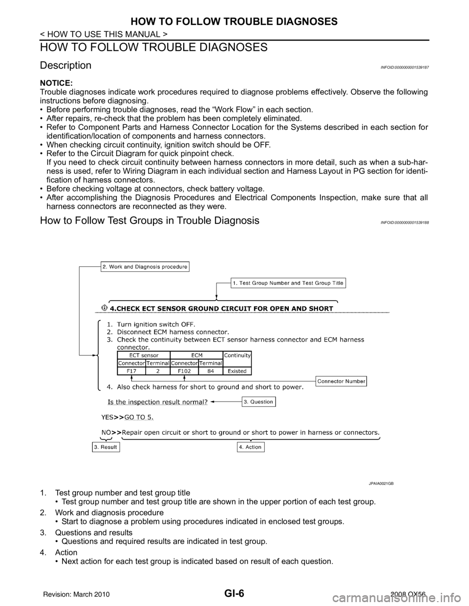
1. Test group number and test group title
• Test group number and test group title are s hown in the upper portion of each test group.
2. Work and diagnosis procedure • Start to diagnose a problem using procedures indicated in enclosed test groups.
3. Questions and results • Questions and required results are indicated in test group.
4. Action • Next action for each test group is indicated based on result of each question.
JPAIA0021GB
Revision: March 2010 2008 QX56
Page 2177 of 4083
SERVICE INFORMATION FOR ELECTRICAL INCIDENTGI-35
< BASIC INSPECTION >
C
DE
F
G H
I
J
K L
M B
GI
N
O P
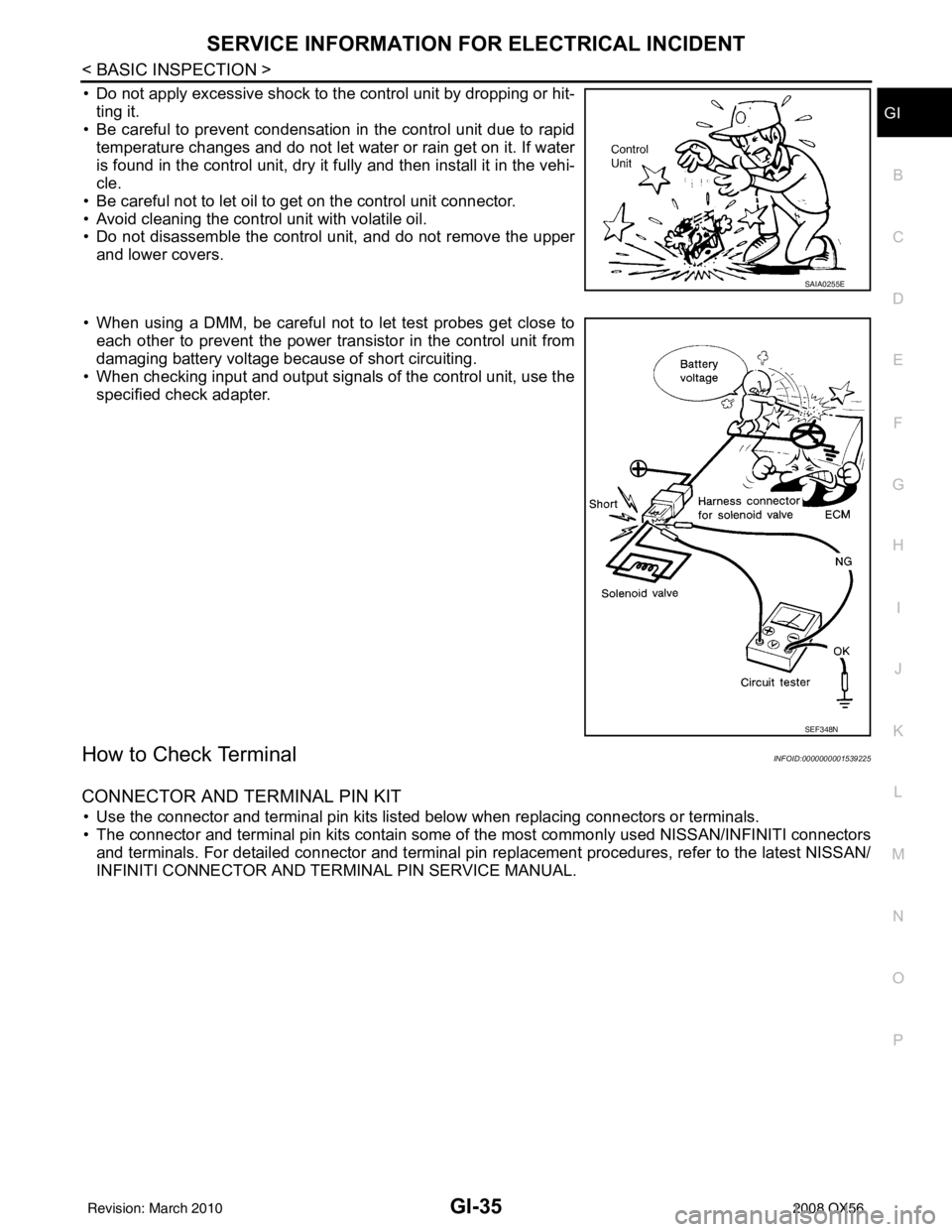
• Do not apply excessive shock to the control unit by dropping or hit- ting it.
• Be careful to prevent condensation in the control unit due to rapid
temperature changes and do not let water or rain get on it. If water
is found in the control unit, dry it fully and then install it in the vehi-
cle.
• Be careful not to let oil to get on the control unit connector.
• Avoid cleaning the control unit with volatile oil.
• Do not disassemble the control unit, and do not remove the upper and lower covers.
• When using a DMM, be careful not to let test probes get close to each other to prevent the power transistor in the control unit from
damaging battery voltage because of short circuiting.
• When checking input and output signals of the control unit, use the specified check adapter.
How to Check TerminalINFOID:0000000001539225
CONNECTOR AND TERMINAL PIN KIT
• Use the connector and terminal pin kits listed below when replacing connectors or terminals.
• The connector and terminal pin kits contain some of the most commonly used NISSAN/INFINITI connectors
and terminals. For detailed connector and terminal pin r eplacement procedures, refer to the latest NISSAN/
INFINITI CONNECTOR AND TERMINAL PIN SERVICE MANUAL.
SAIA0255E
SEF348N
Revision: March 2010 2008 QX56
Page 2183 of 4083
SERVICE INFORMATION FOR ELECTRICAL INCIDENTGI-41
< BASIC INSPECTION >
C
DE
F
G H
I
J
K L
M B
GI
N
O P
Circuit InspectionINFOID:0000000001539227
DESCRIPTION
• In general, testing electrical circuits is an easy task if it is approached in a logical and organized method. Before beginning it is important to have all available information on the system to be tested. Also, get a thor-
ough understanding of system operation. Then you will be able to use the appropriate equipment and follow
the correct test procedure.
• You may have to simulate vehicle vibrations while te sting electrical components. Gently shake the wiring
harness or electrical component to do this.
NOTE:
Refer to GI-35, "
How to Check Terminal" to probe or check terminal.
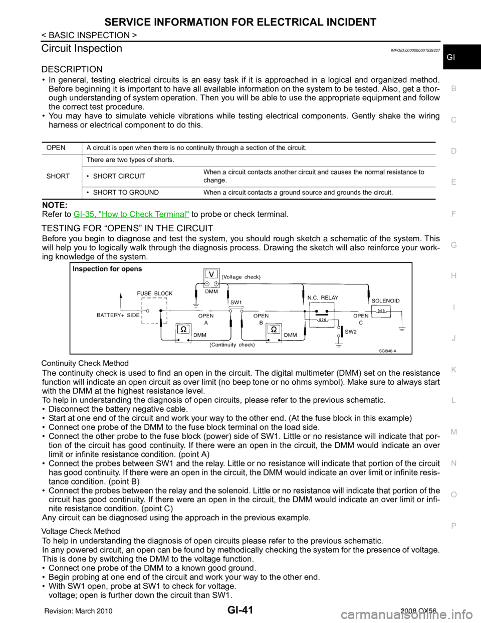
TESTING FOR “OPENS” IN THE CIRCUIT
Before you begin to diagnose and test the system, you should rough sketch a schematic of the system. This
will help you to logically walk through the diagnosis process. Drawing the sketch will also reinforce your work-
ing knowledge of the system.
Continuity Check Method
The continuity check is used to find an open in the circui t. The digital multimeter (DMM) set on the resistance
function will indicate an open circuit as over limit (no beep tone or no ohms symbol). Make sure to always start
with the DMM at the highest resistance level.
To help in understanding the diagnosis of open circui ts, please refer to the previous schematic.
• Disconnect the battery negative cable.
• Start at one end of the circuit and work your way to the other end. (At the fuse block in this example)
• Connect one probe of the DMM to the fuse block terminal on the load side.
• Connect the other probe to the fuse block (power) side of SW1. Little or no resistance will indicate that por-
tion of the circuit has good continuity. If there were an open in the circuit, the DMM would indicate an over
limit or infinite resistance condition. (point A)
• Connect the probes between SW1 and the relay. Little or no resistance will indicate that portion of the circuit
has good continuity. If there were an open in the circuit, t he DMM would indicate an over limit or infinite resis-
tance condition. (point B)
• Connect the probes between the relay and the solenoid. Little or no resistance will indicate that portion of the
circuit has good continuity. If there were an open in the ci rcuit, the DMM would indicate an over limit or infi-
nite resistance condition. (point C)
Any circuit can be diagnosed using the approach in the previous example.
Voltage Check Method
To help in understanding the diagnosis of open circuits please refer to the previous schematic.
In any powered circuit, an open can be found by methodica lly checking the system for the presence of voltage.
This is done by switching the DMM to the voltage function.
• Connect one probe of the DMM to a known good ground.
• Begin probing at one end of the circuit and work your way to the other end.
• With SW1 open, probe at SW1 to check for voltage. voltage; open is further down the circuit than SW1.
OPEN A circuit is open when there is no continuity through a section of the circuit.
SHORT There are two types of shorts.
• SHORT CIRCUIT
When a circuit contacts another circuit and causes the normal resistance to
change.
• SHORT TO GROUND When a circuit contacts a ground source and grounds the circuit.
SGI846-A
Revision: March 2010 2008 QX56
Page 2184 of 4083
GI-42
< BASIC INSPECTION >
SERVICE INFORMATION FOR ELECTRICAL INCIDENT
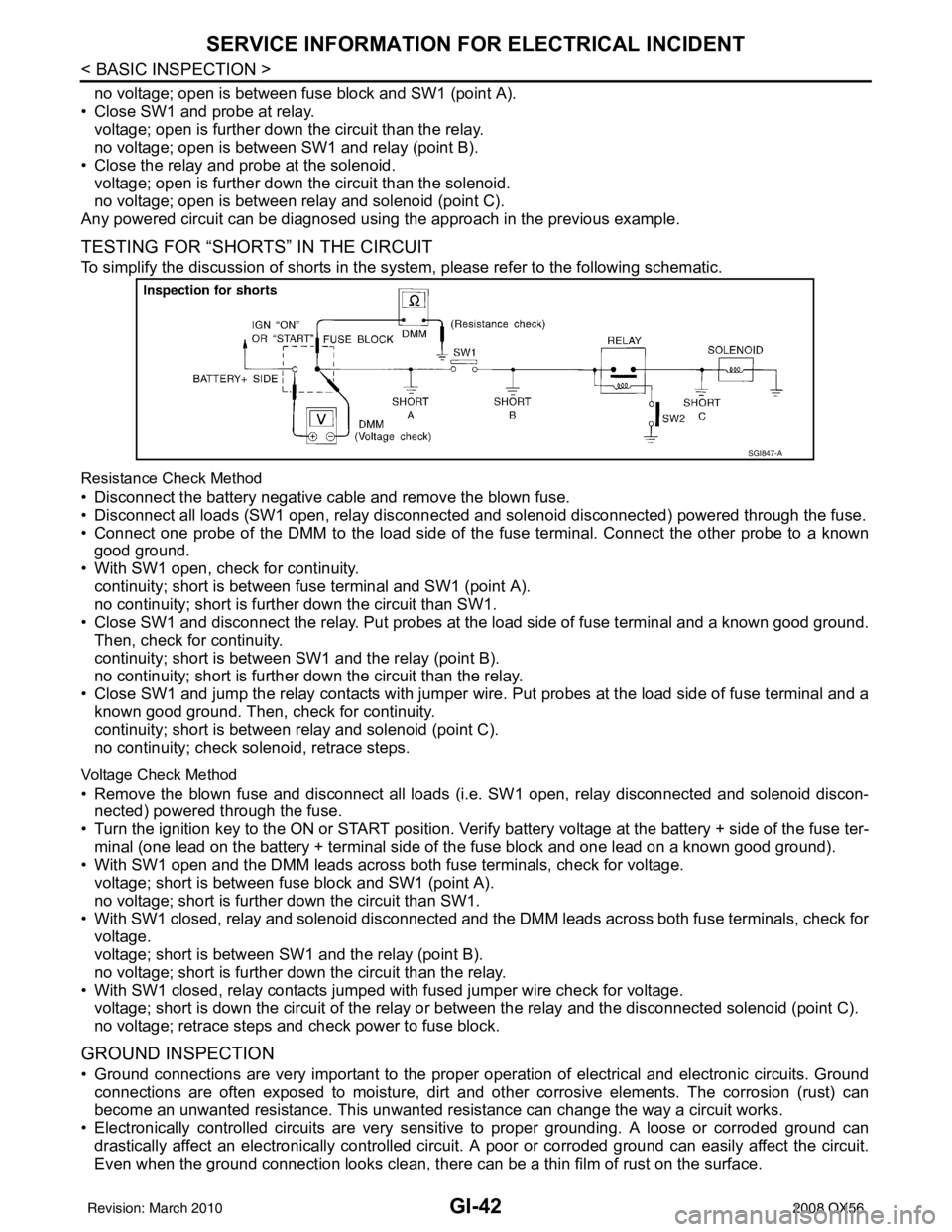
no voltage; open is between fuse block and SW1 (point A).
• Close SW1 and probe at relay. voltage; open is further down the circuit than the relay.
no voltage; open is between SW1 and relay (point B).
• Close the relay and probe at the solenoid. voltage; open is further down the circuit than the solenoid.
no voltage; open is between relay and solenoid (point C).
Any powered circuit can be diagnosed using the approach in the previous example.
TESTING FOR “SHORTS” IN THE CIRCUIT
To simplify the discussion of shorts in the system, please refer to the following schematic.
Resistance Check Method
• Disconnect the battery negative cable and remove the blown fuse.
• Disconnect all loads (SW1 open, relay disconnected and solenoid disconnected) powered through the fuse.
• Connect one probe of the DMM to the load side of the fuse terminal. Connect the other probe to a known good ground.
• With SW1 open, check for continuity. continuity; short is between fuse terminal and SW1 (point A).
no continuity; short is further down the circuit than SW1.
• Close SW1 and disconnect the relay. Put probes at the load side of fuse terminal and a known good ground. Then, check for continuity.
continuity; short is between SW1 and the relay (point B).
no continuity; short is further down the circuit than the relay.
• Close SW1 and jump the relay contacts with jumper wire. Put probes at the load side of fuse terminal and a known good ground. Then, check for continuity.
continuity; short is between relay and solenoid (point C).
no continuity; check solenoid, retrace steps.
Voltage Check Method
• Remove the blown fuse and disconnect all loads (i.e. SW1 open, relay disconnected and solenoid discon-
nected) powered through the fuse.
• Turn the ignition key to the ON or START position. Verify battery voltage at the battery + side of the fuse ter- minal (one lead on the battery + terminal side of the fuse block and one lead on a known good ground).
• With SW1 open and the DMM leads across both fuse terminals, check for voltage. voltage; short is between fuse block and SW1 (point A).
no voltage; short is further down the circuit than SW1.
• With SW1 closed, relay and solenoid disconnected and the DMM leads across both fuse terminals, check for voltage.
voltage; short is between SW1 and the relay (point B).
no voltage; short is further down the circuit than the relay.
• With SW1 closed, relay contacts jumped with fused jumper wire check for voltage. voltage; short is down the circuit of the relay or between the relay and the disconnected solenoid (point C).
no voltage; retrace steps and check power to fuse block.
GROUND INSPECTION
• Ground connections are very important to the proper operation of electrical and electronic circuits. Ground
connections are often exposed to moisture, dirt and other corrosive elements. The corrosion (rust) can
become an unwanted resistance. This unwanted resistance can change the way a circuit works.
• Electronically controlled circuits are very sens itive to proper grounding. A loose or corroded ground can
drastically affect an electronically controlled circuit. A poor or corroded ground can easily affect the circuit.
Even when the ground connection looks clean, there c an be a thin film of rust on the surface.
SGI847-A
Revision: March 2010 2008 QX56
Page 2186 of 4083
GI-44
< BASIC INSPECTION >
SERVICE INFORMATION FOR ELECTRICAL INCIDENT
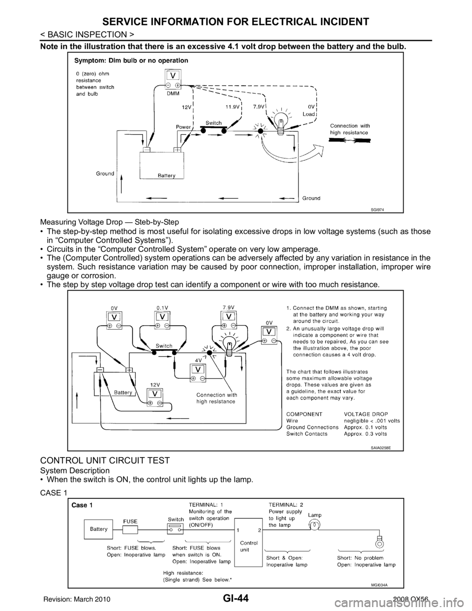
Note in the illustration that there is an excessive 4.1 volt drop between the battery and the bulb.
Measuring Voltage Drop — Steb-by-Step
• The step-by-step method is most useful for isolating excessive drops in low voltage systems (such as those
in “Computer Controlled Systems”).
• Circuits in the “Computer Controlled System” operate on very low amperage.
• The (Computer Controlled) system oper ations can be adversely affected by any variation in resistance in the
system. Such resistance variation may be caused by poor connection, improper installation, improper wire
gauge or corrosion.
• The step by step voltage drop test can identify a component or wire with too much resistance.
CONTROL UNIT CIRCUIT TEST
System Description
• When the switch is ON, the control unit lights up the lamp.
CASE 1
SGI974
SAIA0258E
MGI034A
Revision: March 2010 2008 QX56