2008 INFINITI QX56 Stop
[x] Cancel search: StopPage 2812 of 4083

PG
HARNESSPG-45
< COMPONENT DIAGNOSIS >
C
DE
F
G H
I
J
K L
B A
O P
N
C1 E5 W/24 : To F14
C1 E119 W/16: IPDM E/R (intelligent power distri-
bution module engine room)
C2 E7 GR/2 : Fusible link box (battery) D1 E120 W/6: IPDM E/R (intelligent power distri-
bution module engine room)
C2 E9 — : Body ground E1 E121 BR/12: IPDM E/R (intelligent power distri-
bution module engine room)
D4 E11 B/8 : Front combination lamp LH (without
daytime running lights) C1 E122 W/12: IPDM E/R (intelligent power distri-
bution module engine room)
D4 E11 B/8 : Front combination lamp LH (with
daytime running lights)
C1 E123 BR/8: IPDM E/R (intelligent power distri-
bution module engine room)
D3 E12 B/5 : Stop lamp relay D1 E124 W/6: IPDM E/R (intelligent power distri-
bution module engine room)
D4 E14 — : Body ground F3 E125 B/47: ABS actuator and electric unit
(control unit)
C2 E15 — : Body ground D4 E126 — : Body ground
C1 E16 B/40 : ECM C2 E130 W/2 : Compressor motor relay
E4 E18 GR/2 : Front wheel sensor LH C3 E131 W/2 : Compressor motor relay
D1 E19 W/16 : To F33 C3 E134 GR/6 : ICC brake hold relay
E3 E21 GR/2 : Brake fluid level switch C2 E135 GR/2 : Transfer dropping resister
E2 E23 GR/6 : Front wiper motor C1 E140 BR/6 : Trailer tow relay-2
D4 E24 — : Body ground B2 E153 W/2 : Transfer motor relay
F3 E25 BR/3 : Intelligent key warning buzzer B2 E154 W/2 : Transfer motor relay
C3 E27 BR/2 : Fusible link box (battery) D3 E156 L/4 : Trailer turn relay LH
C2 E30 /1 : Fusible link box (battery )D3 E157 L/4 : Trailer turn relay RH
E3 E31 B/3 : Front pressure sensor D5 E158 B/3 : Front sonar sensor LH outer
E3 E32 B/3 : Rear pressure sensor D5 E159 GR/3 : To E164
E1 E39 W/2 : To F34 B4 E160 GR/3 : To E165
D3 E40 B/3 : To E201 C3 E161 B/3 : Battery current sensor
D3 E41 SMJ : To C1 B4 E162 B/3 : Front sonar sensor LH inner
D3 E42 B/6 : ICC sensor C5 E163 B/3 : Front sonar sensor RH inner
E1 E46 B/5 : Transfer shift high relay D5 E164 GR/3 : To E159
D2 E47 B/5 : Transfer shift lo w relayA4 E165 GR/3 : To E160
C4 E48 B/3 : Refrigerant pressure sensor A3 E166 B/3 : Front sonar sensor RH outer
E3 E49 B/6 : Active booster Engine room sub-harness
D1 E69 L/4 : Transfer shut off relay D3 E201 B/3 : To E40
D5 E101 B/3 : Front turn-fog lamp LH C1 E202 /1 : Fusible link box (battery)
A4 E102 B/3 : Front turn-fog lamp RH C2 E203 — : Engine ground
C3 E103 B/5 : Daytime light relay C3 E204 /1 : Generator
D4 E105 BR/2 : Front and rear washer motor C3 E205 B/3 : Generator
E4 E106 BR/2 : Washer fluid level switch C3 E206 /1 : Generator
B3 E107 B/8 : Front combination lamp LH
C5 E113 W/2 : Cooling fan motor
Revision: March 2010 2008 QX56
Page 2814 of 4083

PG
HARNESSPG-47
< COMPONENT DIAGNOSIS >
C
DE
F
G H
I
J
K L
B A
O P
N
A3 E34 W/24 : To B40
A4 E35 W/12 : To B41
A4 E36 W/2 : To B42
B3 E37 BR/2 : ICC brake switch
B3 E38 W/4 : Stop lamp switch
B3 E109 GR/2 : Pedal adjusting motor
G4 E139 W/8 : To B107
F3 E142 W/24 : Transfer control unit
F3 E143 GR/24 : Transfer control unit
G3 E152 SMJ : To M31
Revision: March 2010
2008 QX56
Page 2827 of 4083

PG-60
< COMPONENT DIAGNOSIS >
HARNESS
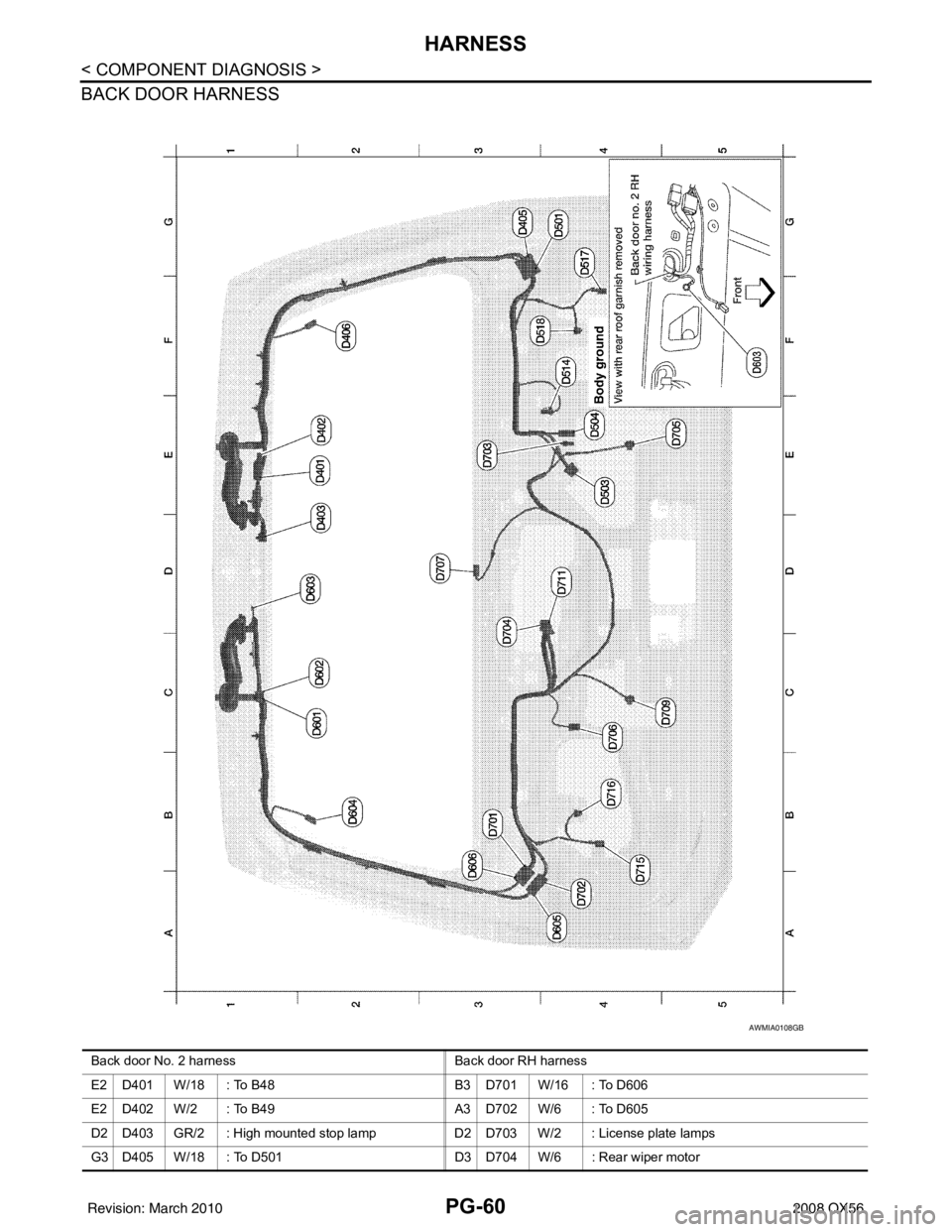
BACK DOOR HARNESS
AWMIA0108GB
Back door No. 2 harnessBack door RH harness
E2 D401 W/18 : To B48 B3 D701 W/16 : To D606
E2 D402 W/2 : To B49 A3 D702 W/6 : To D605
D2 D403 GR/2 : High mounted stop lamp D2 D703 W/2 : License plate lamps
G3 D405 W/18 : To D501 D3 D704 W/6 : Rear wiper motor
Revision: March 2010 2008 QX56
Page 2847 of 4083

PWC-6
< FUNCTION DIAGNOSIS >
POWER WINDOW SYSTEM
REAR POWER WINDOW CONTROL
INPUT/OUTPUT SIGNAL CHART
POWER WINDOW OPERATION
• Power window system is operable during the retained power operation timer after turning ignition switch ON
and OFF.
• Main power window and door lock/unlock switch can open/close all windows.
• Power window and door lock unlock switch RH & rear power window switches LH and RH can open/close the corresponding windows.
REAR POWER VENT WINDOW OPERATION
• Rear power vent window system is operable during the retained power operation timer after turning ignitionswitch ON and OFF.
• Rear power vent window switch can open/close the rear power vent window LH and RH.
POWER WINDOW AUTO-OPERATION
• AUTO UP/DOWN operation can be performed when main power window and door lock/unlock switch or
power window and door lock/unlock switch RH turns to AUTO.
• Main power window and door lock/unlock switch controls rear power window LH/RH auto-operation.
• Encoder continues detecting the movement of power window motor and transmits to front power window
switch LH/RH or rear power window control unit LH/RH as the encoder pulse signal while power window
motor is operating.
• Front power window switch LH/RH or rear power window control unit LH/RH reads the changes of encoder signal and stops AUTO operation when door glass is at fully opened/closed position.
• Power window motor is operable in case encoder is malfunctioning.
RETAINED POWER OPERATION
• Retained power operation is an additional power supply function that enables power window system to oper-
ate during the 45 seconds even when ignition switch is turned OFF
Retained power function cancel conditions
• Front door CLOSE (door switch OFF) →OPEN (door switch ON).
• When ignition switch is ON.
• When timer time passes. (45 seconds)
POWER WINDOW LOCK
The power window lock is designed to lock operation of all windows except for front door window LH.
When in the lock position, the power window lock signal is transmitted to power window and door lock/unlock
switch RH and rear power window control unit LH/RH by power window serial link. This prevents the power
window motor from operating.
Item Input signal to front power window
switch Front power window switch
function Actuator
Power window and
door lock/unlock
switch RH Front power window motor RH UP/
DOWN signal
Power window control Front power window motor RH
Encoder Encoder pulse signal
BCM RAP signal
Item Input signal to front power window
switch Front power window switch
function Actuator
Main power window
and door lock/un-
lock switch Rear power window motor LH/RH UP/
DOWN signal
Power window control Rear power window motor LH/RH
Rear power window
switch LH/RH
Rear power window motor LH/RH UP/
DOWN signal
Rear power window
control unit LH/RH Rear power window
motor control LH
RH UP/DOWN signal
Encoder Encoder pulse signal
BCM Power window serial link signal
Revision: March 2010 2008 QX56
Page 2848 of 4083

POWER WINDOW SYSTEMPWC-7
< FUNCTION DIAGNOSIS >
C
DE
F
G H
I
J
L
M A
B
PWC
N
O P
ANTI-PINCH OPERATION
• Pinch foreign material in the door glass during AUTO-U P operation, and it is the anti-pinch function that low-
ers the door glass 150 mm (5.91 in) or 2 seconds when detected.
• Encoder continues detecting the movement of power window motor and transmits to power window switch
as the encoder pulse signal while power window motor is operating.
• Resistance is applied to the power window motor rotation that changes the frequency of encoder pulse sig-
nal if foreign material is trapped in the door glass.
• Front power window switch LH/RH and rear power window control unit LH/RH controls to lower the window glass for 150 mm (5.91 in) or 2 seconds after it detects encoder pulse signal frequency change.
OPERATION CONDITION
• When all door glass AUTO-UP operation is performed ( anti-pinch function does not operate just before the
door glass closes and is fully closed)
NOTE:
Depending on environment and driving conditions, if a similar impact or load is applied to the door glass, it
may lower.
KEY CYLINDER SWITCH OPERATION
Hold the door key cylinder to the LOCK or UNLOCK dire ction for more than 1 second to OPEN or CLOSE front
power windows when ignition switch is OFF. In addition, it stops when key position is moved to NEUTRAL
when operating.
OPERATION CONDITION
• Ignition switch OFF
• Hold door key cylinder to LOCK position for more than 1 second to perform CLOSE operation of the door glass.
• Hold door key cylinder to UNLOCK position for more than 1 second to perform OPEN operation of the door glass.
KEYLESS POWER WINDOW DOWN OPERATION
Front power windows open when the unlock button on Intelligent Key is activated and kept pressed for more
than 3
(NOTE) seconds with the ignition switch OFF. The windows keep opening if the unlock button is continu-
ously pressed.
The power window opening stops when the following operations are performed:
• When the unlock button is kept pressed more than 15 seconds.
• When the ignition switch is turned ON while the power window opening is operated.
• When the unlock button is released.
While retained power operation is activated, ke yless power window down function cannot be operated.
NOTE:
Keyless power window down operation mode can be changed by “PW DOWN SET” mode in “WORK SUP-
PORT”. Refer to SEC-22, "
CONSULT-III Function (INTELLIGENT KEY)".
NOTE:
Use CONSULT-III to change settings.
MODE1 (3sec)/MODE2 (OFF)/MODE3 (5sec)
Revision: March 2010 2008 QX56
Page 2892 of 4083

BCM (BODY CONTROL MODULE)PWC-51
< ECU DIAGNOSIS >
C
DE
F
G H
I
J
L
M A
B
PWC
N
O P
ECU DIAGNOSIS
BCM (BODY CONTROL MODULE)
Reference ValueINFOID:0000000004874949
VALUES ON THE DIAGNOSIS TOOL
Monitor Item Condition Value/Status
AIR COND SW A/C switch OFF
OFF
A/C switch ON ON
AUT LIGHT SYS Outside of the room is dark
OFF
Outside of the room is bright ON
AUTO LIGHT SW Lighting switch OFF
OFF
Lighting switch AUTO ON
BACK DOOR SW Back door closed
OFF
Back door opened ON
CDL LOCK SW Door lock/unlock switch does not operate
OFF
Press door lock/unlock switch to the LOCK side ON
CDL UNLOCK SW Door lock/unlock switch does not operate
OFF
Press door lock/unlock switch to the UNLOCK side ON
DOOR SW-AS Front door RH closed
OFF
Front door RH opened ON
DOOR SW-DR Front door LH closed
OFF
Front door LH opened ON
DOOR SW-RL Rear door LH closed
OFF
Rear door LH opened ON
DOOR SW-RR Rear door RH closed
OFF
Rear door RH opened ON
ENGINE RUN Engine stopped
OFF
Engine running ON
FR FOG SW Front fog lamp switch OFF
OFF
Front fog lamp switch ON ON
FR WASHER SW Front washer switch OFF
OFF
Front washer switch ON ON
FR WIPER LOW Front wiper switch OFF
OFF
Front wiper switch LO ON
FR WIPER HI Front wiper switch OFF
OFF
Front wiper switch HI ON
FR WIPER INT Front wiper switch OFF
OFF
Front wiper switch INT ON
FR WIPER STOP Any position other than front wiper stop position
OFF
Front wiper stop position ON
HAZARD SW When hazard switch is not pressed
OFF
When hazard switch is pressed ON
LIGHT SW 1ST Lighting switch OFF
OFF
Lighting switch 1st ON
Revision: March 2010 2008 QX56
Page 2893 of 4083

PWC-52
< ECU DIAGNOSIS >
BCM (BODY CONTROL MODULE)
HEADLAMP SW1Headlamp switch OFF OFF
Headlamp switch 1st
ON
HEADLAMP SW2 Headlamp switch OFF
OFF
Headlamp switch 1st ON
HI BEAM SW High beam switch OFF
OFF
High beam switch HI ON
IGN ON SW Ignition switch OFF or ACC
OFF
Ignition switch ON ON
IGN SW CAN Ignition switch OFF or ACC
OFF
Ignition switch ON ON
INT VOLUME Wiper intermittent dial is in a dial position 1 - 7 1 - 7
I-KEY LOCK LOCK button of Intelligent Key is not pressed
OFF
LOCK button of Intelligent Key is pressed ON
I-KEY UNLOCK UNLOCK button of Intelligent Key is not pressed
OFF
UNLOCK button of Intelligent Key is pressed ON
KEY ON SW Mechanical key is removed from key cylinder
OFF
Mechanical key is inserted to key cylinder ON
OIL PRESS SW • Ignition switch OFF or ACC
• Engine running
OFF
Ignition switch ON ON
PASSING SW Other than lighting switch PASS
OFF
Lighting switch PASS ON
REAR DEF SW Rear window defogger switch OFF
OFF
Rear window defogger switch ON ON
RR WASHER SW Rear washer switch OFF
OFF
Rear washer switch ON ON
RR WIPER INT Rear wiper switch OFF
OFF
Rear wiper switch INT ON
RR WIPER ON Rear wiper switch OFF
OFF
Rear wiper switch ON ON
RR WIPER STOP Rear wiper stop position
OFF
Other than rear wiper stop position ON
TAIL LAMP SW Lighting switch OFF
OFF
Lighting switch 1ST ON
TRNK OPNR SW When back door opener switch is not pressed
OFF
When back door opener switch is pressed ON
TURN SIGNAL L Turn signal switch OFF
OFF
Turn signal switch LH ON
TURN SIGNAL R Turn signal switch OFF
OFF
Turn signal switch RH ON
VEHICLE SPEED While driving Equivalent to speedometer reading
Monitor Item
Condition Value/Status
Revision: March 2010 2008 QX56
Page 2896 of 4083

BCM (BODY CONTROL MODULE)PWC-55
< ECU DIAGNOSIS >
C
DE
F
G H
I
J
L
M A
B
PWC
N
O P
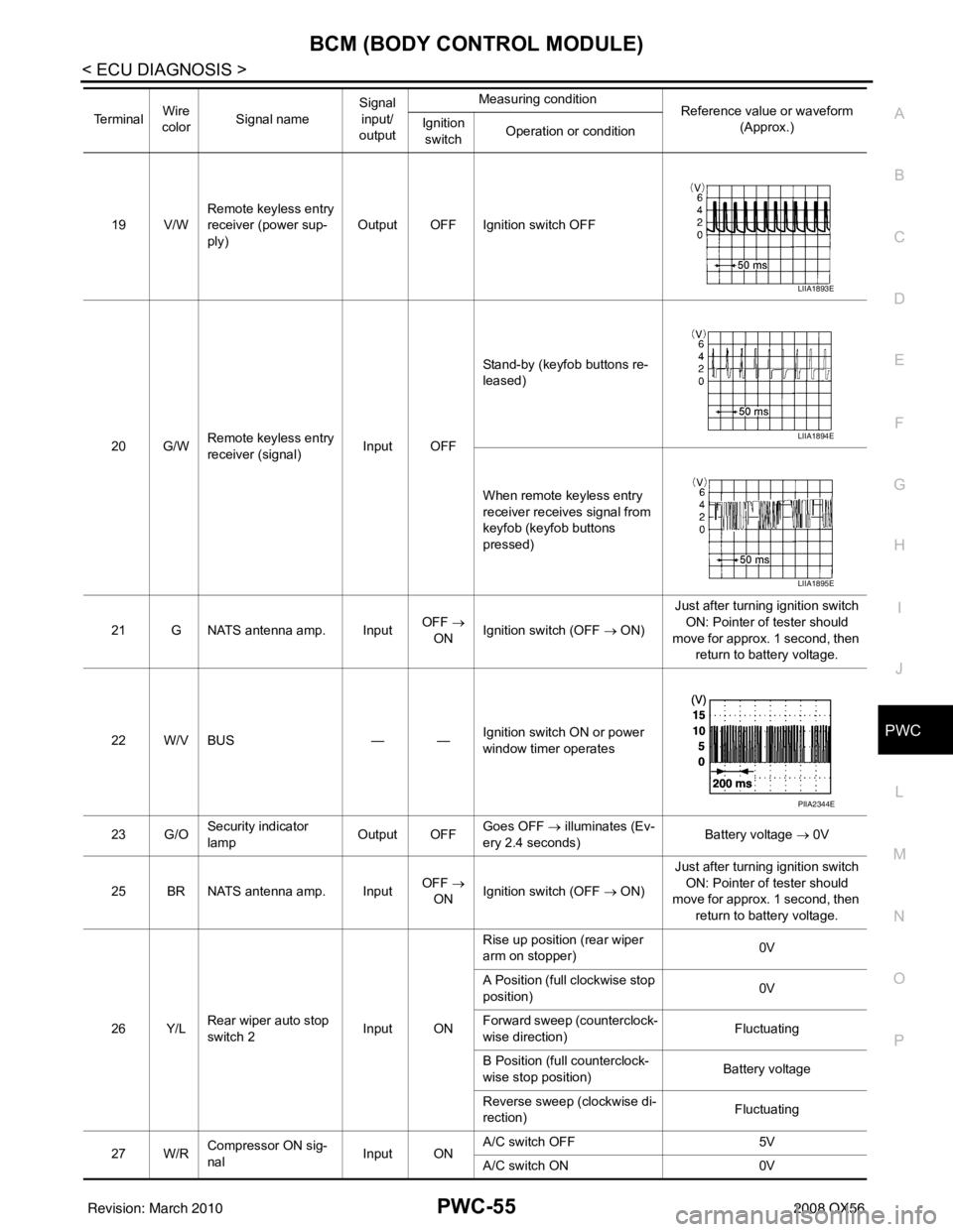
19 V/W Remote keyless entry
receiver (power sup-
ply) Output OFF Ignition switch OFF
20 G/W Remote keyless entry
receiver (signal) Input OFFStand-by (keyfob buttons re-
leased)
When remote keyless entry
receiver receives signal from
keyfob (keyfob buttons
pressed)
21 G NATS antenna amp. Input OFF
→
ON Ignition switch (OFF → ON) Just after turning ignition switch
ON: Pointer of tester should
move for approx. 1 second, then return to battery voltage.
22 W/V BUS — —Ignition switch ON or power
window timer operates
23 G/O Security indicator
lamp Output OFF
Goes OFF
→ illuminates (Ev-
ery 2.4 seconds) Battery voltage
→ 0V
25 BR NATS antenna amp. Input OFF
→
ON Ignition switch (OFF → ON) Just after turning ignition switch
ON: Pointer of tester should
move for approx. 1 second, then return to battery voltage.
26 Y/L Rear wiper auto stop
switch 2 Input ONRise up position (rear wiper
arm on stopper)
0V
A Position (full clockwise stop
position) 0V
Forward sweep (counterclock-
wise direction) Fluctuating
B Position (full counterclock-
wise stop position) Battery voltage
Reverse sweep (clockwise di-
rection) Fluctuating
27 W/R Compressor ON sig-
nal Input ONA/C switch OFF
5V
A/C switch ON 0V
Te r m i n a l
Wire
color Signal name Signal
input/
output Measuring condition
Reference value or waveform
(Approx.)
Ignition
switch Operation or condition
LIIA1893E
LIIA1894E
LIIA1895E
PIIA2344E
Revision: March 2010
2008 QX56