2008 INFINITI FX35 clock
[x] Cancel search: clockPage 2837 of 3924
FUEL LEVEL SENSOR UNIT, FUEL FILTER AND FUEL PUMP ASSEMBLY
FL-5
< SERVICE INFORMATION >
C
D E
F
G H
I
J
K L
M A
FL
NP
O
2. Release the fuel pressure from the fuel lines. Refer to
EC-87, "Fuel Pressure Check" (VQ35DE) or EC-
665, "Fuel Pressure Check" (VK45DE).
3. Open fuel filler lid.
4. Open filler cap and release the pressure inside fuel tank.
5. Remove rear seat cushion. Refer to SE-95, "
Removal and Installation".
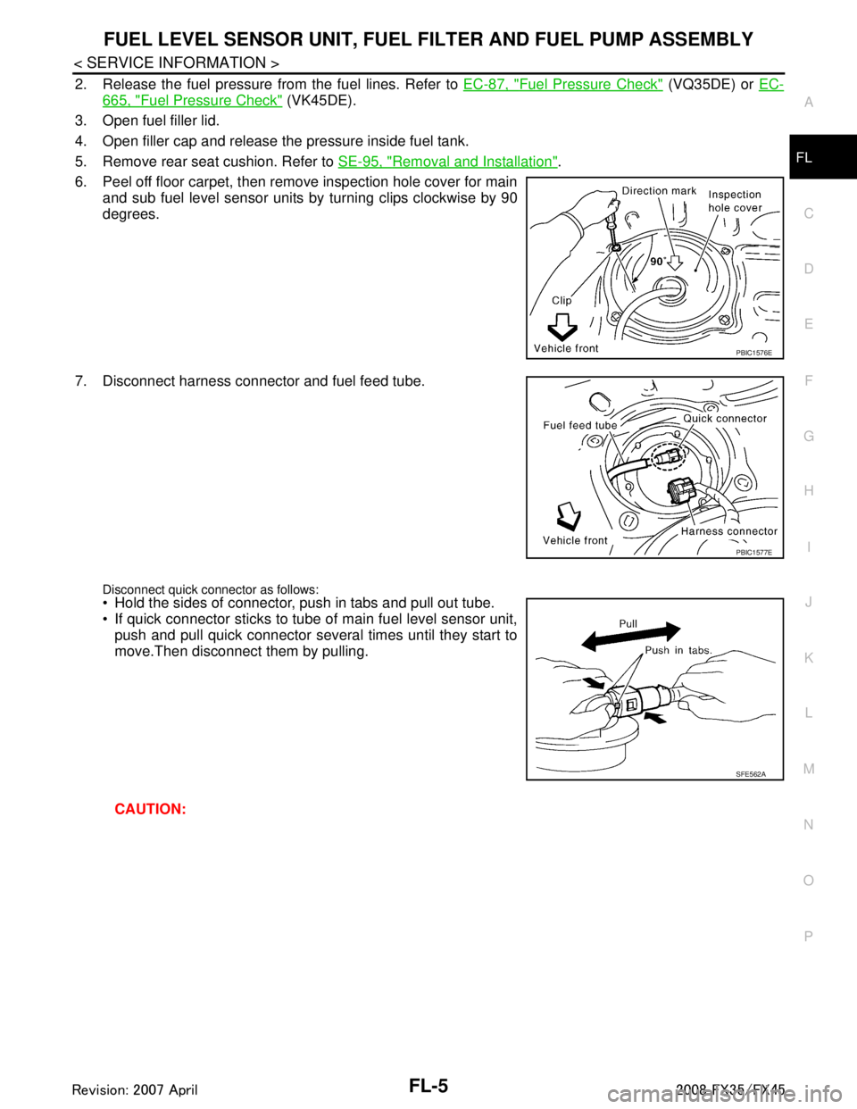
6. Peel off floor carpet, then remove inspection hole cover for main and sub fuel level sensor units by turning clips clockwise by 90
degrees.
7. Disconnect harness connector and fuel feed tube.
Disconnect quick connector as follows: Hold the sides of connector, push in tabs and pull out tube.
If quick connector sticks to tube of main fuel level sensor unit, push and pull quick connector several times until they start to
move.Then disconnect them by pulling.
CAUTION:
PBIC1576E
PBIC1577E
SFE562A
3AA93ABC3ACD3AC03ACA3AC03AC63AC53A913A773A893A873A873A8E3A773A983AC73AC93AC03AC3
3A893A873A873A8F3A773A9D3AAF3A8A3A8C3A863A9D3AAF3A8B3A8C
Page 2918 of 3924
SQUEAK AND RATTLE TROUBLE DIAGNOSESGW-5
< SERVICE INFORMATION >
C
DE
F
G H
J
K L
M A
B
GW
N
O P
SQUEAK AND RATTLE TROUBLE DIAGNOSES
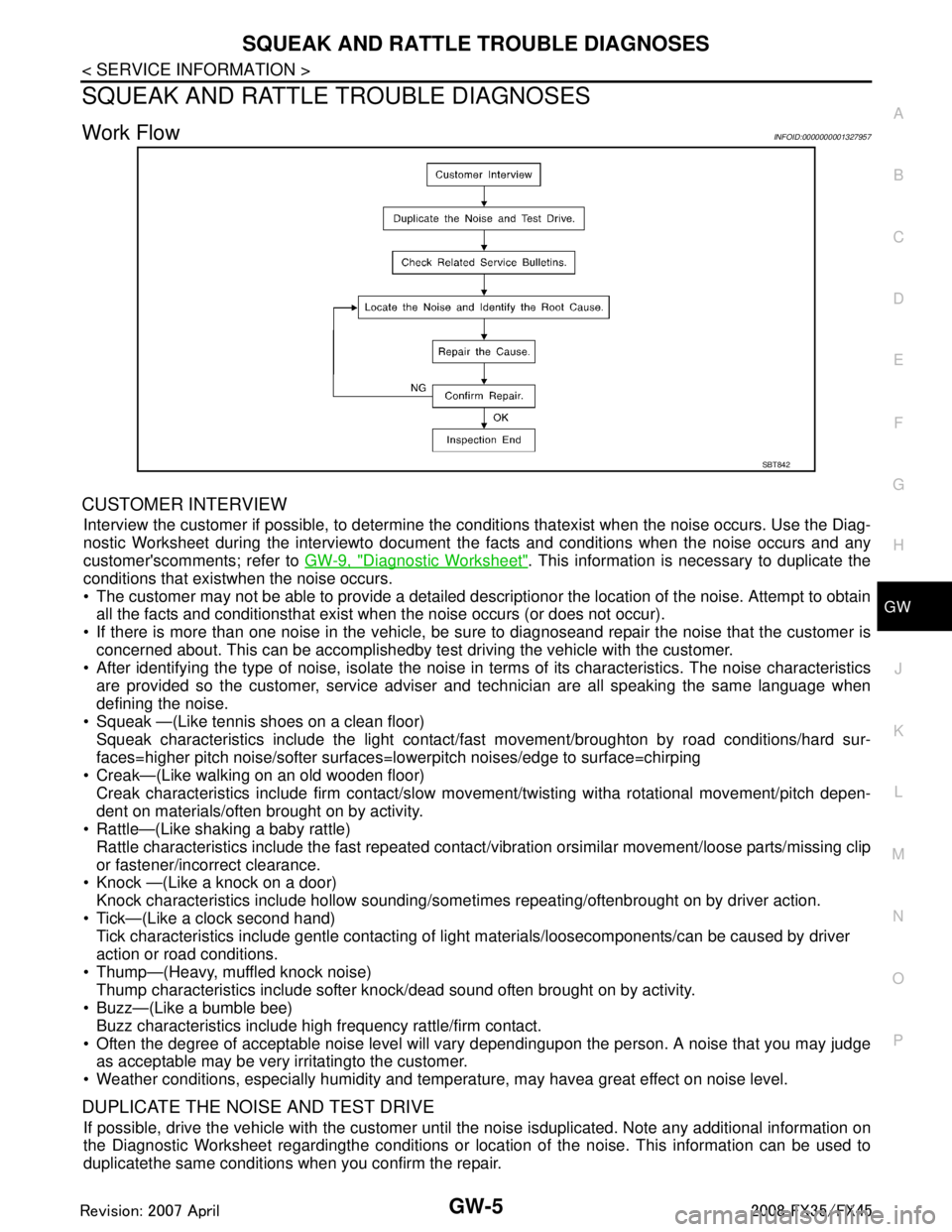
Work FlowINFOID:0000000001327957
CUSTOMER INTERVIEW
Interview the customer if possible, to determine the conditions thatexist when the noise occurs. Use the Diag-
nostic Worksheet during the interviewto document t he facts and conditions when the noise occurs and any
customer'scomments; refer to GW-9, "
Diagnostic Worksheet". This information is necessary to duplicate the
conditions that existwhen the noise occurs.
The customer may not be able to provide a detailed descriptionor the location of the noise. Attempt to obtain all the facts and conditionsthat exist w hen the noise occurs (or does not occur).
If there is more than one noise in the vehicle, be sure to diagnoseand repair the noise that the customer is
concerned about. This can be accomplishedby test driving the vehicle with the customer.
After identifying the type of noise, isolate the noise in terms of its characteristics. The noise characteristics
are provided so the customer, service adviser and technician are all speaking the same language when
defining the noise.
Squeak —(Like tennis shoes on a clean floor)
Squeak characteristics include the light contact/fa st movement/broughton by road conditions/hard sur-
faces=higher pitch noise/softer surfaces=l owerpitch noises/edge to surface=chirping
Creak—(Like walking on an old wooden floor)
Creak characteristics include firm contact/slow mo vement/twisting witha rotational movement/pitch depen-
dent on materials/often brought on by activity.
Rattle—(Like shaking a baby rattle)
Rattle characteristics include the fast repeated contac t/vibration orsimilar movement/loose parts/missing clip
or fastener/incorrect clearance.
Knock —(Like a knock on a door)
Knock characteristics include hollow sounding/some times repeating/oftenbrought on by driver action.
Tick—(Like a clock second hand) Tick characteristics include gentle contacting of li ght materials/loosecomponents/can be caused by driver
action or road conditions.
Thump—(Heavy, muffled knock noise) Thump characteristics include softer k nock/dead sound often brought on by activity.
Buzz—(Like a bumble bee)
Buzz characteristics include high frequency rattle/firm contact.
Often the degree of acceptable noise level will vary dependingupon the person. A noise that you may judge as acceptable may be very irritatingto the customer.
Weather conditions, especially humidity and temper ature, may havea great effect on noise level.
DUPLICATE THE NOISE AND TEST DRIVE
If possible, drive the vehicle with the customer until the noise isduplicated. Note any additional information on
the Diagnostic Worksheet regardingthe conditions or location of the noise. This information can be used to
duplicatethe same conditions when you confirm the repair.
SBT842
3AA93ABC3ACD3AC03ACA3AC03AC63AC53A913A773A893A873A873A8E3A773A983AC73AC93AC03AC3
3A893A873A873A8F3A773A9D3AAF3A8A3A8C3A863A9D3AAF3A8B3A8C
Page 3005 of 3924
IP-4
< SERVICE INFORMATION >
SQUEAK AND RATTLE TROUBLE DIAGNOSES
SQUEAK AND RATTLE TROUBLE DIAGNOSES
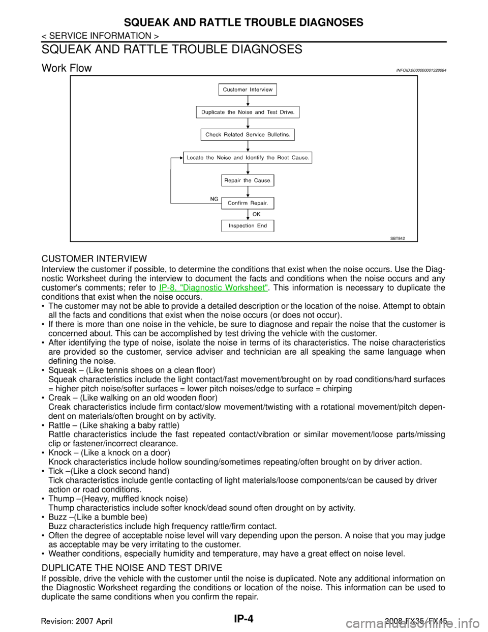
Work FlowINFOID:0000000001328084
CUSTOMER INTERVIEW
Interview the customer if possible, to determine the c onditions that exist when the noise occurs. Use the Diag-
nostic Worksheet during the interview to document the facts and conditions when the noise occurs and any
customer's comments; refer to IP-8, "
Diagnostic Worksheet". This information is necessary to duplicate the
conditions that exist when the noise occurs.
The customer may not be able to provide a detailed description or the location of the noise. Attempt to obtain all the facts and conditions that exist w hen the noise occurs (or does not occur).
If there is more than one noise in the vehicle, be sure to diagnose and repair the noise that the customer is
concerned about. This can be accomplished by te st driving the vehicle with the customer.
After identifying the type of noise, isolate the noise in terms of its characteristics. The noise characteristics
are provided so the customer, service adviser and technician are all speaking the same language when
defining the noise.
Squeak – (Like tennis shoes on a clean floor)
Squeak characteristics include the light contact/fast movement/brought on by road conditions/hard surfaces
= higher pitch noise/softer surfaces = lower pitch noises/edge to surface = chirping
Creak – (Like walking on an old wooden floor)
Creak characteristics include firm contact/slow mo vement/twisting with a rotational movement/pitch depen-
dent on materials/often brought on by activity.
Rattle – (Like shaking a baby rattle)
Rattle characteristics include the fast repeated contac t/vibration or similar movement/loose parts/missing
clip or fastener/incorrect clearance.
Knock – (Like a knock on a door)
Knock characteristics include hollow sounding/someti mes repeating/often brought on by driver action.
Tick –(Like a clock second hand) Tick characteristics include gentle contacting of light materials/loose components/can be caused by driver
action or road conditions.
Thump –(Heavy, muffled knock noise) Thump characteristics include softer k nock/dead sound often drought on by activity.
Buzz –(Like a bumble bee)
Buzz characteristics include hi gh frequency rattle/firm contact.
Often the degree of acceptable noise level will vary depending upon the person. A noise that you may judge as acceptable may be very irritating to the customer.
Weather conditions, especially humidity and temperat ure, may have a great effect on noise level.
DUPLICATE THE NOISE AND TEST DRIVE
If possible, drive the vehicle with the customer until the noise is duplicated. Note any additional information on
the Diagnostic Worksheet regarding the conditions or lo cation of the noise. This information can be used to
duplicate the same conditions when you confirm the repair.
SBT842
3AA93ABC3ACD3AC03ACA3AC03AC63AC53A913A773A893A873A873A8E3A773A983AC73AC93AC03AC3
3A893A873A873A8F3A773A9D3AAF3A8A3A8C3A863A9D3AAF3A8B3A8C
Page 3012 of 3924
INSTRUMENT PANEL ASSEMBLYIP-11
< SERVICE INFORMATION >
C
DE
F
G H
J
K L
M A
B
IP
N
O P
Removal and InstallationINFOID:0000000001328088
WORK STEP
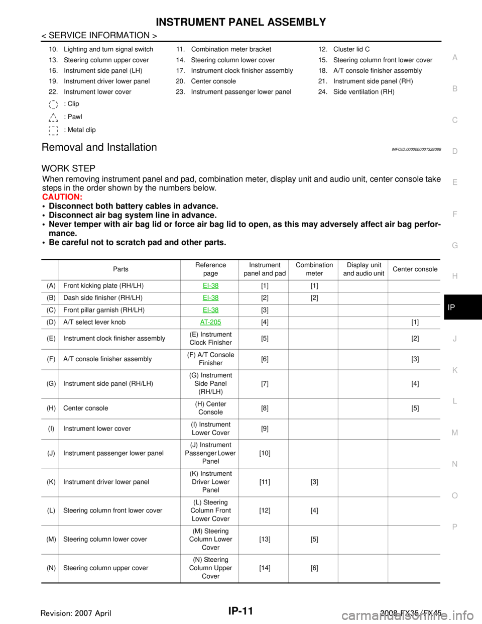
When removing instrument panel and pad, combination me ter, display unit and audio unit, center console take
steps in the order shown by the numbers below.
CAUTION:
Disconnect both battery cables in advance.
Disconnect air bag system line in advance.
Never temper with air bag lid or force air bag lid to open, as this may adversely affect air bag perfor-
mance.
Be careful not to scratch pad and other parts.
10. Lighting and turn signal switch 11. Combination meter bracket 12. Cluster lid C
13. Steering column upper cover 14. Steering column lower cover 15. Steering column front lower cover
16. Instrument side panel (LH) 17. Instrument clock finisher assembly 18. A/T console finisher assembly
19. Instrument driver lower panel 20. Center console 21. Instrument side panel (RH)
22. Instrument lower cover 23. Instrument passenger lower panel 24. Side ventilation (RH)
: Clip
: Pawl
: Metal clip
Parts Reference
page Instrument
panel and pad Combination
meter Display unit
and audio unit Center console
(A) Front kicking plate (RH/LH) EI-38
[1] [1]
(B) Dash side finisher (RH/LH) EI-38
[2] [2]
(C) Front pillar garnish (RH/LH) EI-38
[3]
(D) A/T select lever knob AT- 2 0 5
[4] [1]
(E) Instrument clock finisher assembly (E) Instrument
Clock Finisher [5] [2]
(F) A/T console finisher assembly (F) A/T Console
Finisher [6] [3]
(G) Instrument side panel (RH/LH) (G) Instrument
Side Panel (RH/LH) [7] [4]
(H) Center console (H) Center
Console [8] [5]
(I) Instrument lower cover (I) Instrument
Lower Cover [9]
(J) Instrument passenger lower panel (J) Instrument
Passenger Lower
Panel [10]
(K) Instrument driver lower panel (K) Instrument
Driver Lower Panel [11] [3]
(L) Steering column front lower cover (L) Steering
Column Front Lower Cover [12] [4]
(M) Steering column lower cover (M) Steering
Column Lower
Cover [13] [5]
(N) Steering column upper cover (N) Steering
Column Upper Cover [14] [6]
3AA93ABC3ACD3AC03ACA3AC03AC63AC53A913A773A893A873A873A8E3A773A983AC73AC93AC03AC3
3A893A873A873A8F3A773A9D3AAF3A8A3A8C3A863A9D3AAF3A8B3A8C
Page 3013 of 3924
![INFINITI FX35 2008 Service Manual
IP-12
< SERVICE INFORMATION >
INSTRUMENT PANEL ASSEMBLY
[]: Number indicates step in removal procedures.
REMOVAL
(A) Front Kicking Plate (RH/LH)
Remove front kicking plate (RH/LH). Refer to EI-38.
(B INFINITI FX35 2008 Service Manual
IP-12
< SERVICE INFORMATION >
INSTRUMENT PANEL ASSEMBLY
[]: Number indicates step in removal procedures.
REMOVAL
(A) Front Kicking Plate (RH/LH)
Remove front kicking plate (RH/LH). Refer to EI-38.
(B](/manual-img/42/57017/w960_57017-3012.png)
IP-12
< SERVICE INFORMATION >
INSTRUMENT PANEL ASSEMBLY
[]: Number indicates step in removal procedures.
REMOVAL
(A) Front Kicking Plate (RH/LH)
Remove front kicking plate (RH/LH). Refer to EI-38.
(B) Dash Side Finisher (RH/LH)
1. Remove plastics nut.
2. Remove dash side finisher (RH/LH). Refer to EI-38
.
(C) Front Pillar Garnish (RH/LH)
Pull to inside of vehicle, disengage metal clips and remove front pillar garnish. Refer to EI-38.
(D) A/T Select Lever Knob
1. Pull down knob cover.
2. Remove lock-pin of select lever knob.
3. Lift up select lever knob and remove select lever knob.
Refer to AT-205, "
Control Device Removal and Installation".
(E) Instrument Clock Finisher
1. Remove screw and then pull back to your side of instrument
clock finisher.
2. Disconnect clips and harness connector, and remove instrument clock finisher.
(F) A/T Console Finisher
(O) Wiper and washer switch (O) Wiper and
Washer Switch [15] [7]
(P) Lighting and turn signal switch (P) Lighting and
Turn Signal Switch [16] [8]
(Q) Steering lock escutcheon (Q) Steering Lock
Escutcheon [17] [9]
(R) Combination meter assembly (R) Combination
Meter Assembly [18] [10]
(S) Cluster lid C (S) Cluster Lid C [19] [1] (T) Display unit and audio unit (T) Display Unit
and Audio Unit [20] [2]
(U) Front defroster grille (RH/LH) (U) Front
Defroster Grille (RH/LH) [21]
(V) Combination meter bracket (V) Combination
Meter Bracket [22]
(W) Side ventilation (RH/LH) (W) Side
Ventilation (RH/LH) [23]
(X) Instrument panel and pad (X) Instrument
Panel and Pad [24]
Parts
Reference
page Instrument
panel and pad Combination
meter Display unit
and audio unit Center console
: Clip
: Pawl
PIIB8535E
3AA93ABC3ACD3AC03ACA3AC03AC63AC53A913A773A893A873A873A8E3A773A983AC73AC93AC03AC3
3A893A873A873A8F3A773A9D3AAF3A8A3A8C3A863A9D3AAF3A8B3A8C
Page 3018 of 3924
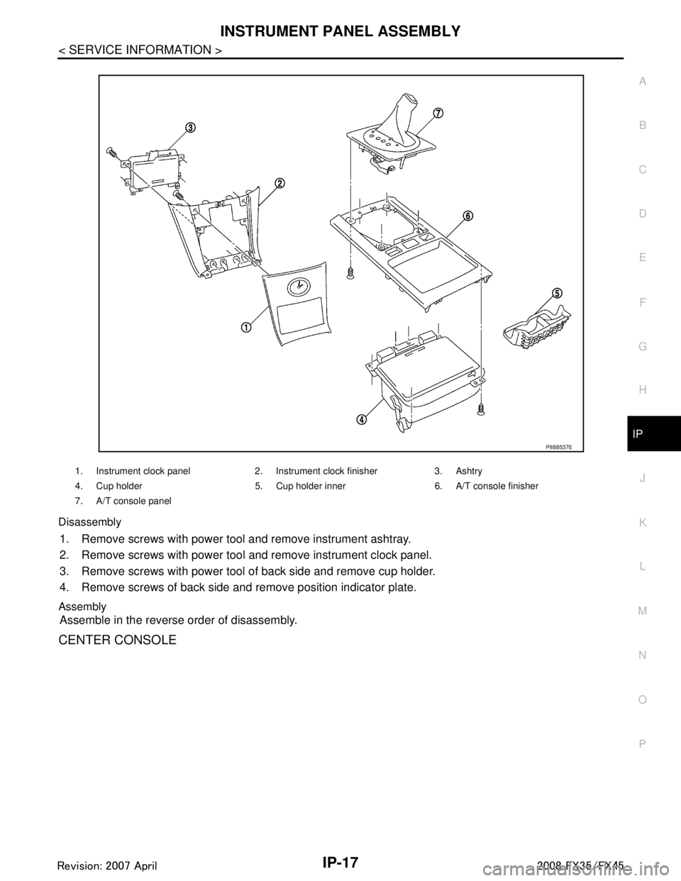
INSTRUMENT PANEL ASSEMBLYIP-17
< SERVICE INFORMATION >
C
DE
F
G H
J
K L
M A
B
IP
N
O P
Disassembly
1. Remove screws with power tool and remove instrument ashtray.
2. Remove screws with power tool and remove instrument clock panel.
3. Remove screws with power tool of back side and remove cup holder.
4. Remove screws of back side and remove position indicator plate.
Assembly
Assemble in the reverse order of disassembly.
CENTER CONSOLE
1. Instrument clock panel 2. Instrument clock finisher 3. Ashtry
4. Cup holder 5. Cup holder inner 6. A/T console finisher
7. A/T console panel
PIIB8537E
3AA93ABC3ACD3AC03ACA3AC03AC63AC53A913A773A893A873A873A8E3A773A983AC73AC93AC03AC3
3A893A873A873A8F3A773A9D3AAF3A8A3A8C3A863A9D3AAF3A8B3A8C
Page 3131 of 3924
HEADLAMP - XENON TYPE -LT-29
< SERVICE INFORMATION >
C
DE
F
G H
I
J
L
M A
B
LT
N
O P
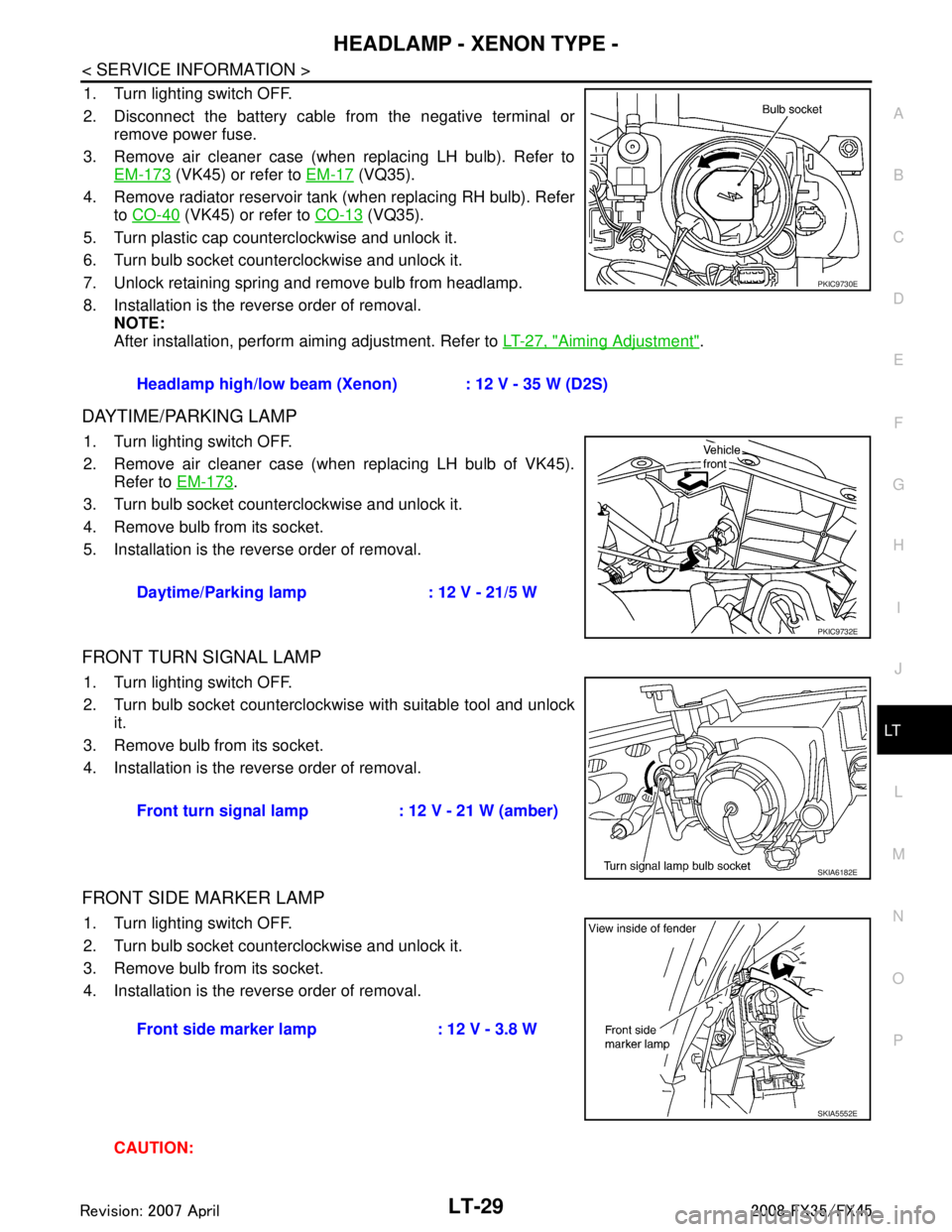
1. Turn lighting switch OFF.
2. Disconnect the battery cable from the negative terminal or remove power fuse.
3. Remove air cleaner case (when replacing LH bulb). Refer to EM-173
(VK45) or refer to EM-17 (VQ35).
4. Remove radiator reservoir tank (when replacing RH bulb). Refer to CO-40
(VK45) or refer to CO-13 (VQ35).
5. Turn plastic cap counterclockwise and unlock it.
6. Turn bulb socket counterclockwise and unlock it.
7. Unlock retaining spring and remove bulb from headlamp.
8. Installation is the reverse order of removal. NOTE:
After installation, perform aiming adjustment. Refer to LT-27, "
Aiming Adjustment".
DAYTIME/PARKING LAMP
1. Turn lighting switch OFF.
2. Remove air cleaner case (when replacing LH bulb of VK45).
Refer to EM-173
.
3. Turn bulb socket counterclockwise and unlock it.
4. Remove bulb from its socket.
5. Installation is the reverse order of removal.
FRONT TURN SIGNAL LAMP
1. Turn lighting switch OFF.
2. Turn bulb socket counterclockwise with suitable tool and unlock it.
3. Remove bulb from its socket.
4. Installation is the reverse order of removal.
FRONT SIDE MARKER LAMP
1. Turn lighting switch OFF.
2. Turn bulb socket counterclockwise and unlock it.
3. Remove bulb from its socket.
4. Installation is the reverse order of removal.
CAUTION:Headlamp high/low beam (Xenon) : 12 V - 35 W (D2S)
PKIC9730E
Daytime/Parking lamp : 12 V - 21/5 W
PKIC9732E
Front turn signal lamp : 12 V - 21 W (amber)
SKIA6182E
Front side marker lamp : 12 V - 3.8 W
SKIA5552E
3AA93ABC3ACD3AC03ACA3AC03AC63AC53A913A773A893A873A873A8E3A773A983AC73AC93AC03AC3
3A893A873A873A8F3A773A9D3AAF3A8A3A8C3A863A9D3AAF3A8B3A8C
Page 3132 of 3924
LT-30
< SERVICE INFORMATION >
HEADLAMP - XENON TYPE -
After installing bulb, be sure to install plastic cap and bulb socket securely to insure watertight-
ness.
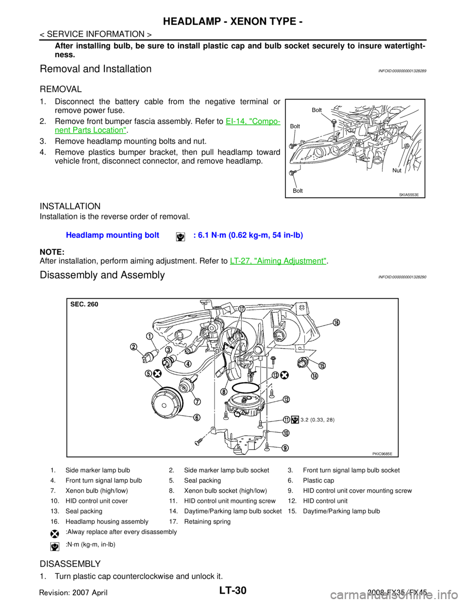
Removal and InstallationINFOID:0000000001328289
REMOVAL
1. Disconnect the battery cable from the negative terminal or remove power fuse.
2. Remove front bumper fascia assembly. Refer to EI-14, "
Compo-
nent Parts Location".
3. Remove headlamp mounting bolts and nut.
4. Remove plastics bumper bracket, then pull headlamp toward vehicle front, disconnect connector, and remove headlamp.
INSTALLATION
Installation is the reverse order of removal.
NOTE:
After installation, perform aiming adjustment. Refer to LT-27, "
Aiming Adjustment".
Disassembly and AssemblyINFOID:0000000001328290
DISASSEMBLY
1. Turn plastic cap counterclockwise and unlock it.
SKIA5553E
Headlamp mounting bolt : 6.1 N·m (0.62 kg-m, 54 in-lb)
1. Side marker lamp bulb 2. Side marker lamp bulb socket 3. Front turn signal lamp bulb socket
4. Front turn signal lamp bulb 5. Seal packing 6. Plastic cap
7. Xenon bulb (high/low) 8. Xenon bulb socket (high/low) 9. HID control unit cover mounting screw
10. HID control unit cover 11. HID control unit mounting screw 12. HID control unit
13. Seal packing 14. Daytime/Parking lamp bulb socket 15. Daytime/Parking lamp bulb
16. Headlamp housing assembly 17. Retaining spring
:Alway replace after every disassembly
:N·m (kg-m, in-lb)
PKIC9685E
3AA93ABC3ACD3AC03ACA3AC03AC63AC53A913A773A893A873A873A8E3A773A983AC73AC93AC03AC3
3A893A873A873A8F3A773A9D3AAF3A8A3A8C3A863A9D3AAF3A8B3A8C