2008 INFINITI FX35 clock
[x] Cancel search: clockPage 3358 of 3924
PARKING BRAKE SYSTEMPB-3
< SERVICE INFORMATION >
C
DE
G H
I
J
K L
M A
B
PB
N
O P
PARKING BRAKE SYSTEM
On-Vehicle InspectionINFOID:0000000001327646
PEDAL STROKE
• When parking brake pedal is operated with a force of 200 N (20.4 kg, 44.9 lb), make sure the parking brake
pedal stroke is within the specified number of notches . (Check it by listening and counting the ratchet clicks.)
Make sure that brake warning lamp comes on when parking brake pedal is depressed with in one notch.
INSPECT COMPONENTS
Make sure the components are installed properly (check for looseness, backlash, etc.).
Check parking brake pedal assembly for bend, damage and cracks, and replace if necessary.
Check cable for wear and damage, and replace if necessary.
Check parking brake switch for malfunction, and replace if necessary.
ADJUSTMENT
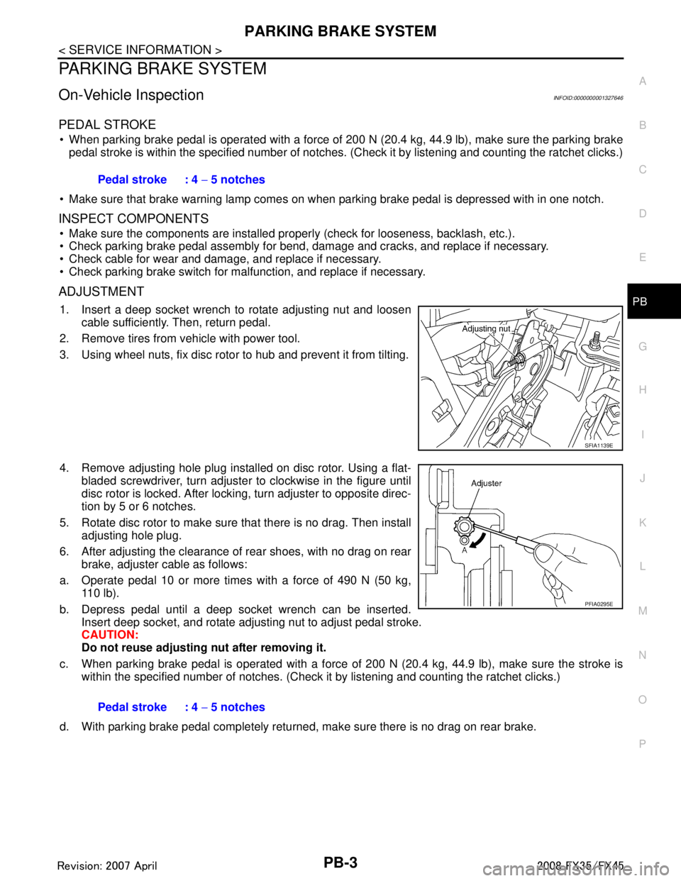
1. Insert a deep socket wrench to rotate adjusting nut and loosen cable sufficiently. Then, return pedal.
2. Remove tires from vehicle with power tool.
3. Using wheel nuts, fix disc rotor to hub and prevent it from tilting.
4. Remove adjusting hole plug installed on disc rotor. Using a flat- bladed screwdriver, turn adjuster to clockwise in the figure until
disc rotor is locked. After locking, turn adjuster to opposite direc-
tion by 5 or 6 notches.
5. Rotate disc rotor to make sure that there is no drag. Then install adjusting hole plug.
6. After adjusting the clearance of rear shoes, with no drag on rear brake, adjuster cable as follows:
a. Operate pedal 10 or more times with a force of 490 N (50 kg, 110 lb).
b. Depress pedal until a deep socket wrench can be inserted. Insert deep socket, and rotate adjusting nut to adjust pedal stroke.
CAUTION:
Do not reuse adjusting nut after removing it.
c. When parking brake pedal is operated with a force of 200 N (20.4 kg, 44.9 lb), make sure the stroke is
within the specified number of notches. (Check it by listening and counting the ratchet clicks.)
d. With parking brake pedal completely returned, make sure there is no drag on rear brake. Pedal stroke : 4
− 5 notches
SFIA1139E
Pedal stroke : 4 − 5 notches
PFIA0295E
3AA93ABC3ACD3AC03ACA3AC03AC63AC53A913A773A893A873A873A8E3A773A983AC73AC93AC03AC3
3A893A873A873A8F3A773A9D3AAF3A8A3A8C3A863A9D3AAF3A8B3A8C
Page 3425 of 3924

HARNESSPG-61
< SERVICE INFORMATION >
C
DE
F
G H
I
J
L
M A
B
PG
N
O P
Code Section Wiring Diagram Name
A/C ATC Air Conditioner
AF1B1 EC Air Fuel Ratio Sensor 1 Bank 1
AF1B2 EC Air Fuel Ratio Sensor 1 Bank 2
AF1HB1 EC Air Fuel Ratio Sensor 1 Heater Bank 1
AF1HB2 EC Air Fuel Ratio Sensor 1 Heater Bank 2
APPS1 EC Accelerator Pedal Position Sensor
APPS2 EC Accelerator Pedal Position Sensor
APPS3 EC Accelerator Pedal Position Sensor
ASC/BS EC Automatic Speed Control Device (ASCD) Brake Switch
ASC/SW EC Automatic Speed Control Device (ASCD) Steering Switch
ASCBOF EC Automatic Speed Control Device (ASCD) Brake Switch
ASCIND EC Automatic Speed Contro l Device (ASCD) Indicator
AT/IND DI A/T Indicator Lamp
AUDIO AV Audio
AUT/DP SE Automatic Drive Positioner
AUTO/L LT Automatic Light System
AWD TF AWD Control System
B/CLOS BL Back Door Closure System
BACK/L LT Back-Up Lamp
BRK/SW EC Brake Switch
CAN AT CAN Communication Line
CAN EC CAN Communication Line
CAN LAN CAN System
CHARGE SC Charging System
CHIME DI Warning Chime
CLOCK DI Clock
COMBSW LT Combination Switch
COMM AV Audio Visual Communication Line
COMPAS DI Compass
COOL/F EC Cooling Fan Control
D/LOCK BL Power Door Lock
DEF GW Rear Window Defogger
DTRL LT Headlamp - With Daytime Light System
ECM/PW EC ECM Power Supply for Back-Up
ECTS EC Engine Coolant Temperature Sensor
ETC1 EC Electric Throttle Control Function
ETC2 EC Electric Throttle Control Motor Relay
ETC3 EC Electric Throttle Control Motor
F/FOG LT Front Fog Lamp
F/PUMP EC Fuel Pump
FTS AT A/T Fluid Temperature Sensor Circuit
FTTS EC Fuel Tank Temperature Sensor
FUELB1 EC Fuel Injection System Function (Bank 1)
FUELB2 EC Fuel Injection System Function (Bank 2)
3AA93ABC3ACD3AC03ACA3AC03AC63AC53A913A773A893A873A873A8E3A773A983AC73AC93AC03AC3
3A893A873A873A8F3A773A9D3AAF3A8A3A8C3A863A9D3AAF3A8B3A8C
Page 3480 of 3924
POWER STEERING GEAR AND LINKAGEPS-25
< SERVICE INFORMATION >
C
DE
F
H I
J
K L
M A
B
PS
N
O P
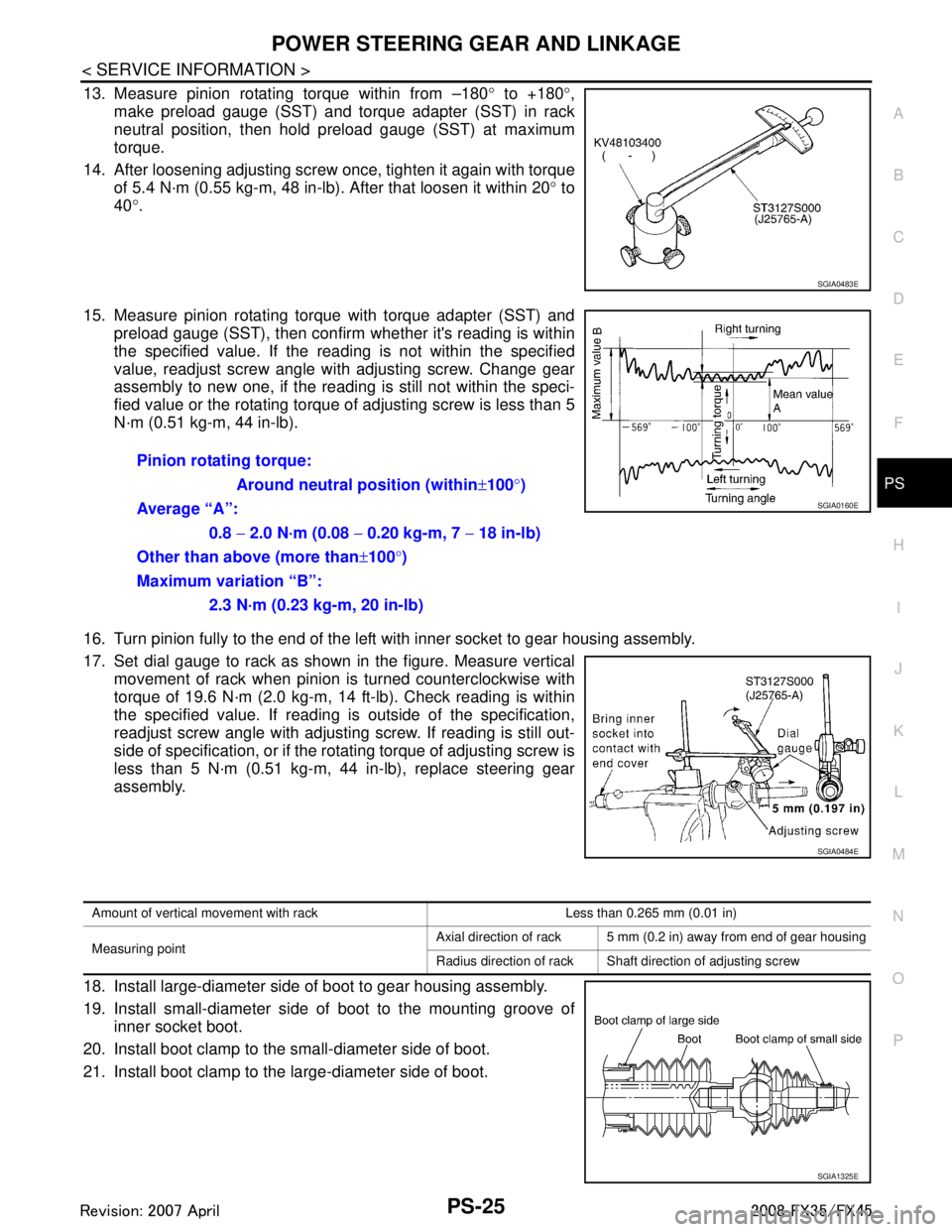
13. Measure pinion rotating torque within from –180 ° to +180 °,
make preload gauge (SST) and torque adapter (SST) in rack
neutral position, then hold preload gauge (SST) at maximum
torque.
14. After loosening adjusting screw once, tighten it again with torque of 5.4 N·m (0.55 kg-m, 48 in-lb). After that loosen it within 20 ° to
40 °.
15. Measure pinion rotating torque with torque adapter (SST) and preload gauge (SST), then confirm w hether it's reading is within
the specified value. If the r eading is not within the specified
value, readjust screw angle with adjusting screw. Change gear
assembly to new one, if the readi ng is still not within the speci-
fied value or the rotating torque of adjusting screw is less than 5
N·m (0.51 kg-m, 44 in-lb).
16. Turn pinion fully to the end of the left with inner socket to gear housing assembly.
17. Set dial gauge to rack as shown in the figure. Measure vertical movement of rack when pinion is turned counterclockwise with
torque of 19.6 N·m (2.0 kg-m, 14 ft-lb). Check reading is within
the specified value. If reading is outside of the specification,
readjust screw angle with adjusting screw. If reading is still out-
side of specification, or if the rotating torque of adjusting screw is
less than 5 N·m (0.51 kg-m, 44 in-lb), replace steering gear
assembly.
18. Install large-diameter side of boot to gear housing assembly.
19. Install small-diameter side of boot to the mounting groove of inner socket boot.
20. Install boot clamp to the small-diameter side of boot.
21. Install boot clamp to the large-diameter side of boot.
SGIA0483E
Pinion rotating torque:
Around neutral position (within ±100 °)
Average “A”:
0.8 − 2.0 N·m (0.08 − 0.20 kg-m, 7 − 18 in-lb)
Other than above (more than ±100 °)
Maximum variation “B”:
2.3 N·m (0.23 kg-m, 20 in-lb)
SGIA0160E
SGIA0484E
Amount of vertical movement with rack Less than 0.265 mm (0.01 in)
Measuring point Axial direction of rack 5 mm (0.2 in) away from end of gear housing
Radius direction of rack Shaft direction of adjusting screw
SGIA1325E
3AA93ABC3ACD3AC03ACA3AC03AC63AC53A913A773A893A873A873A8E3A773A983AC73AC93AC03AC3
3A893A873A873A8F3A773A9D3AAF3A8A3A8C3A863A9D3AAF3A8B3A8C
Page 3507 of 3924
REAR WHEEL HUB AND KNUCKLERAX-9
< SERVICE INFORMATION >
CEF
G H
I
J
K L
M A
B
RAX
N
O P
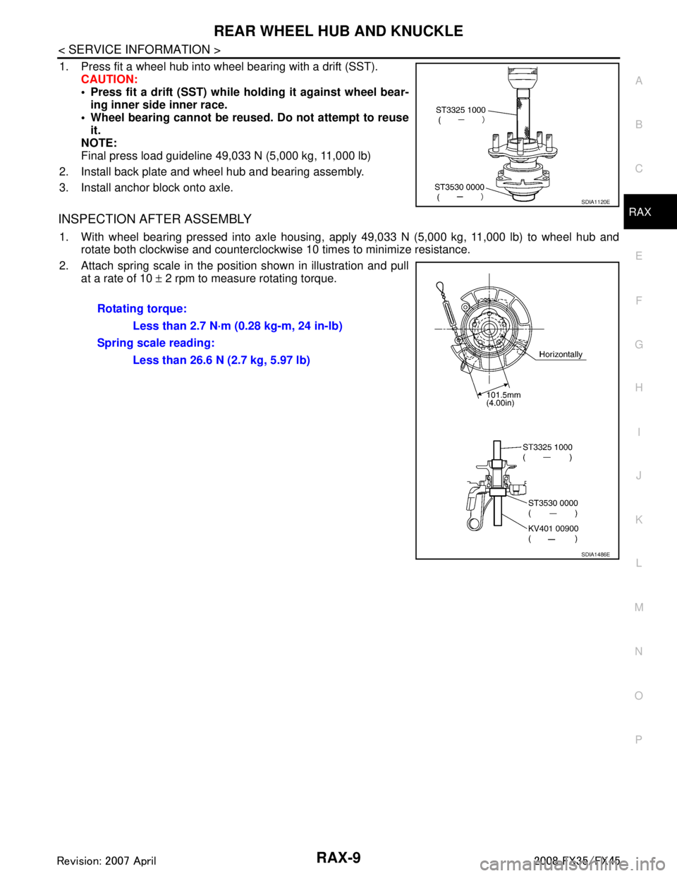
1. Press fit a wheel hub into wheel bearing with a drift (SST). CAUTION:
• Press fit a drift (SST) while ho lding it against wheel bear-
ing inner side inner race.
Wheel bearing cannot be reused. Do not attempt to reuse it.
NOTE:
Final press load guideline 49,033 N (5,000 kg, 11,000 lb)
2. Install back plate and wheel hub and bearing assembly.
3. Install anchor block onto axle.
INSPECTION AFTER ASSEMBLY
1. With wheel bearing pressed into axle housing, apply 49,033 N (5,000 kg, 11,000 lb) to wheel hub and rotate both clockwise and counterclockwise 10 times to minimize resistance.
2. Attach spring scale in the position shown in illustration and pull at a rate of 10 ± 2 rpm to measure rotating torque.
SDIA1120E
Rotating torque:
Less than 2.7 N·m (0.28 kg-m, 24 in-lb)
Spring scale reading: Less than 26.6 N (2.7 kg, 5.97 lb)
SDIA1486E
3AA93ABC3ACD3AC03ACA3AC03AC63AC53A913A773A893A873A873A8E3A773A983AC73AC93AC03AC3
3A893A873A873A8F3A773A9D3AAF3A8A3A8C3A863A9D3AAF3A8B3A8C
Page 3519 of 3924
RF-4
< SERVICE INFORMATION >
SQUEAK AND RATTLE TROUBLE DIAGNOSES
SQUEAK AND RATTLE TROUBLE DIAGNOSES
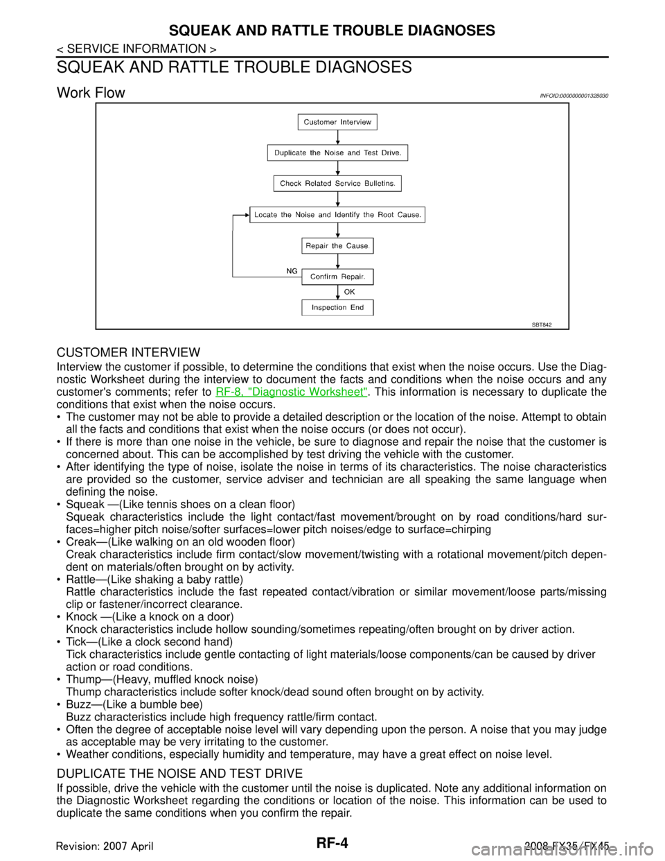
Work FlowINFOID:0000000001328030
CUSTOMER INTERVIEW
Interview the customer if possible, to determine the c onditions that exist when the noise occurs. Use the Diag-
nostic Worksheet during the interview to document the facts and conditions when the noise occurs and any
customer's comments; refer to RF-8, "
Diagnostic Worksheet". This information is necessary to duplicate the
conditions that exist when the noise occurs.
The customer may not be able to provide a detailed description or the location of the noise. Attempt to obtain all the facts and conditions that exist w hen the noise occurs (or does not occur).
If there is more than one noise in the vehicle, be sure to diagnose and repair the noise that the customer is
concerned about. This can be accomplished by test driving the vehicle with the customer.
After identifying the type of noise, isolate the noise in terms of its characteristics. The noise characteristics
are provided so the customer, service adviser and technician are all speaking the same language when
defining the noise.
Squeak —(Like tennis shoes on a clean floor)
Squeak characteristics include the light contact/fa st movement/brought on by road conditions/hard sur-
faces=higher pitch noise/softer surfaces=l ower pitch noises/edge to surface=chirping
Creak—(Like walking on an old wooden floor)
Creak characteristics include firm contact/slow mo vement/twisting with a rotational movement/pitch depen-
dent on materials/often brought on by activity.
Rattle—(Like shaking a baby rattle)
Rattle characteristics include the fast repeated contac t/vibration or similar movement/loose parts/missing
clip or fastener/incorrect clearance.
Knock —(Like a knock on a door)
Knock characteristics include hollow sounding/someti mes repeating/often brought on by driver action.
Tick—(Like a clock second hand) Tick characteristics include gentle contacting of light materials/loose components/can be caused by driver
action or road conditions.
Thump—(Heavy, muffled knock noise) Thump characteristics include softer k nock/dead sound often brought on by activity.
Buzz—(Like a bumble bee)
Buzz characteristics include hi gh frequency rattle/firm contact.
Often the degree of acceptable noise level will vary depending upon the person. A noise that you may judge as acceptable may be very irritating to the customer.
Weather conditions, especially humidity and temperat ure, may have a great effect on noise level.
DUPLICATE THE NOISE AND TEST DRIVE
If possible, drive the vehicle with the customer until the noise is duplicated. Note any additional information on
the Diagnostic Worksheet regarding the conditions or lo cation of the noise. This information can be used to
duplicate the same conditions when you confirm the repair.
SBT842
3AA93ABC3ACD3AC03ACA3AC03AC63AC53A913A773A893A873A873A8E3A773A983AC73AC93AC03AC3
3A893A873A873A8F3A773A9D3AAF3A8A3A8C3A863A9D3AAF3A8B3A8C
Page 3645 of 3924
SE-6
< SERVICE INFORMATION >
SQUEAK AND RATTLE TROUBLE DIAGNOSES
SQUEAK AND RATTLE TROUBLE DIAGNOSES
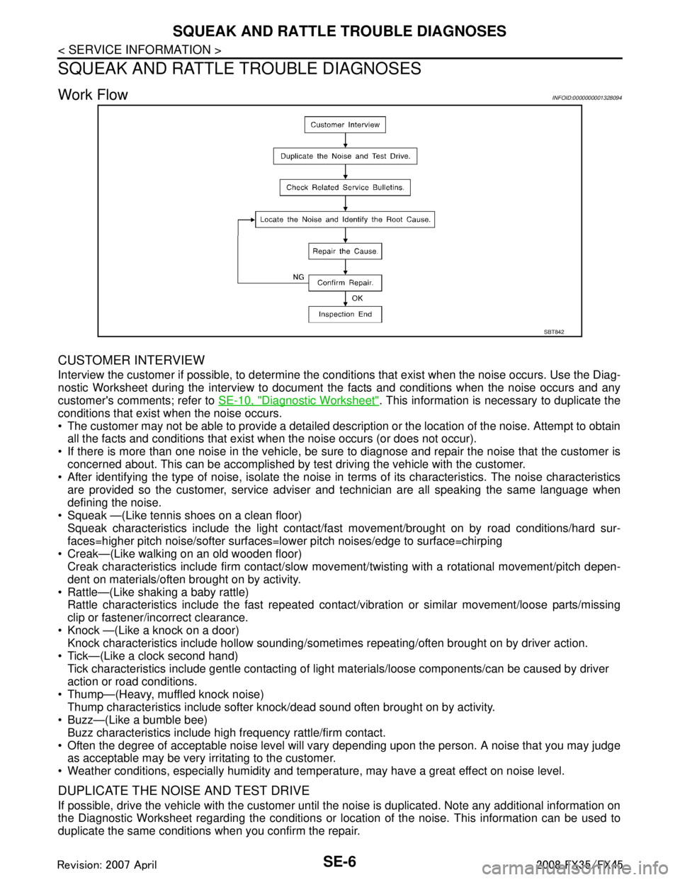
Work FlowINFOID:0000000001328094
CUSTOMER INTERVIEW
Interview the customer if possible, to determine the c onditions that exist when the noise occurs. Use the Diag-
nostic Worksheet during the interview to document the facts and conditions when the noise occurs and any
customer's comments; refer to SE-10, "
Diagnostic Worksheet". This information is necessary to duplicate the
conditions that exist when the noise occurs.
The customer may not be able to provide a detailed description or the location of the noise. Attempt to obtain all the facts and conditions that exist w hen the noise occurs (or does not occur).
If there is more than one noise in the vehicle, be sure to diagnose and repair the noise that the customer is
concerned about. This can be accomplished by test driving the vehicle with the customer.
After identifying the type of noise, isolate the noise in terms of its characteristics. The noise characteristics
are provided so the customer, service adviser and technician are all speaking the same language when
defining the noise.
Squeak —(Like tennis shoes on a clean floor)
Squeak characteristics include the light contact/fa st movement/brought on by road conditions/hard sur-
faces=higher pitch noise/softer surfaces=l ower pitch noises/edge to surface=chirping
Creak—(Like walking on an old wooden floor)
Creak characteristics include firm contact/slow mo vement/twisting with a rotational movement/pitch depen-
dent on materials/often brought on by activity.
Rattle—(Like shaking a baby rattle)
Rattle characteristics include the fast repeated contac t/vibration or similar movement/loose parts/missing
clip or fastener/incorrect clearance.
Knock —(Like a knock on a door)
Knock characteristics include hollow sounding/someti mes repeating/often brought on by driver action.
Tick—(Like a clock second hand) Tick characteristics include gentle contacting of light materials/loose components/can be caused by driver
action or road conditions.
Thump—(Heavy, muffled knock noise) Thump characteristics include softer k nock/dead sound often brought on by activity.
Buzz—(Like a bumble bee)
Buzz characteristics include hi gh frequency rattle/firm contact.
Often the degree of acceptable noise level will vary depending upon the person. A noise that you may judge as acceptable may be very irritating to the customer.
Weather conditions, especially humidity and temperat ure, may have a great effect on noise level.
DUPLICATE THE NOISE AND TEST DRIVE
If possible, drive the vehicle with the customer until the noise is duplicated. Note any additional information on
the Diagnostic Worksheet regarding the conditions or lo cation of the noise. This information can be used to
duplicate the same conditions when you confirm the repair.
SBT842
3AA93ABC3ACD3AC03ACA3AC03AC63AC53A913A773A893A873A873A8E3A773A983AC73AC93AC03AC3
3A893A873A873A8F3A773A9D3AAF3A8A3A8C3A863A9D3AAF3A8B3A8C
Page 3774 of 3924
SPIRAL CABLESRS-37
< SERVICE INFORMATION >
C
DE
F
G
I
J
K L
M A
B
SRS
N
O P
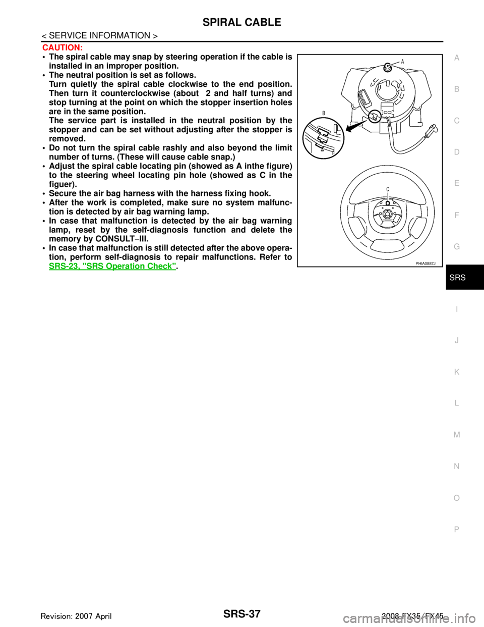
CAUTION:
The spiral cable may snap by steering operation if the cable is
installed in an improper position.
The neutral position is set as follows. Turn quietly the spiral cable clockwise to the end position.
Then turn it counterclockwise (about 2 and half turns) and
stop turning at the point on which the stopper insertion holes
are in the same position.
The service part is installed in the neutral position by the
stopper and can be set without adjusting after the stopper is
removed.
Do not turn the spiral cable r ashly and also beyond the limit
number of turns. (These will cause cable snap.)
Adjust the spiral cable locating pin (showed as A inthe figure) to the steering wheel locating pin hole (showed as C in the
figuer).
Secure the air bag harness wi th the harness fixing hook.
After the work is completed, make sure no system malfunc- tion is detected by air bag warning lamp.
In case that malfunction is detected by the air bag warning lamp, reset by the self-diagnosis function and delete the
memory by CONSULT −III.
In case that malfunction is still detected after the above opera-
tion, perform self-diagnosis to repair malfunctions. Refer to
SRS-23, "
SRS Operation Check".PHIA0887J
3AA93ABC3ACD3AC03ACA3AC03AC63AC53A913A773A893A873A873A8E3A773A983AC73AC93AC03AC3
3A893A873A873A8F3A773A9D3AAF3A8A3A8C3A863A9D3AAF3A8B3A8C
Page 3921 of 3924
WW-46
< SERVICE INFORMATION >
POWER SOCKET
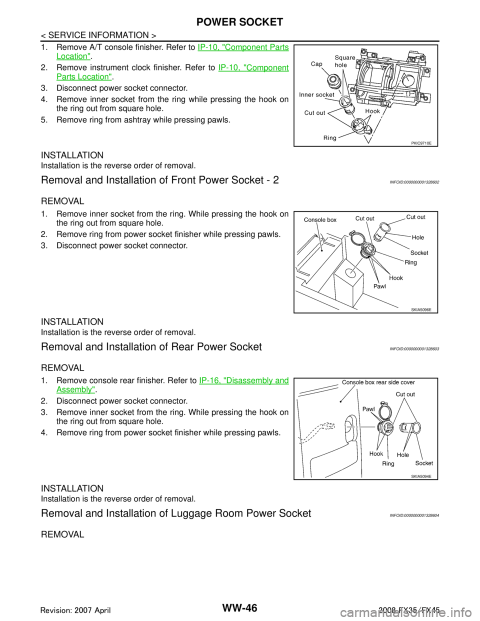
1. Remove A/T console finisher. Refer to IP-10, "Component Parts
Location".
2. Remove instrument clock finisher. Refer to IP-10, "
Component
Parts Location".
3. Disconnect power socket connector.
4. Remove inner socket from the ring while pressing the hook on the ring out from square hole.
5. Remove ring from ashtray while pressing pawls.
INSTALLATION
Installation is the reverse order of removal.
Removal and Installation of Front Power Socket - 2INFOID:0000000001328602
REMOVAL
1. Remove inner socket from the ring. While pressing the hook on
the ring out from square hole.
2. Remove ring from power socket finisher while pressing pawls.
3. Disconnect power socket connector.
INSTALLATION
Installation is the reverse order of removal.
Removal and Installation of Rear Power SocketINFOID:0000000001328603
REMOVAL
1. Remove console rear finisher. Refer to IP-16, "Disassembly and
Assembly".
2. Disconnect power socket connector.
3. Remove inner socket from the ring. While pressing the hook on the ring out from square hole.
4. Remove ring from power socket finisher while pressing pawls.
INSTALLATION
Installation is the reverse order of removal.
Removal and Installation of Luggage Room Power SocketINFOID:0000000001328604
REMOVAL
PKIC9710E
SKIA5096E
SKIA5094E
3AA93ABC3ACD3AC03ACA3AC03AC63AC53A913A773A893A873A873A8E3A773A983AC73AC93AC03AC3
3A893A873A873A8F3A773A9D3AAF3A8A3A8C3A863A9D3AAF3A8B3A8C