2008 INFINITI FX35 lock
[x] Cancel search: lockPage 3769 of 3924
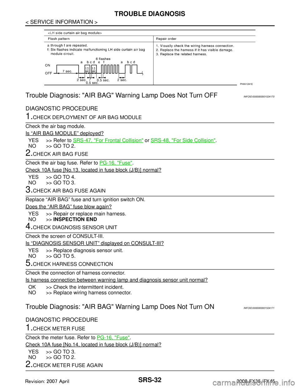
SRS-32
< SERVICE INFORMATION >
TROUBLE DIAGNOSIS
Trouble Diagnosis: "AIR BAG" Warning Lamp Does Not Turn OFF
INFOID:0000000001524170
DIAGNOSTIC PROCEDURE
1.CHECK DEPLOYMENT OF AIR BAG MODULE
Check the air bag module.
Is
“AIR BAG MODULE” deployed?
YES >> Refer to SRS-47, "For Frontal Collision" or SRS-48, "For Side Collision".
NO >> GO TO 2.
2.CHECK AIR BAG FUSE
Check the air bag fuse. Refer to PG-16, "
Fuse".
Check 10A fuse [No.13, located in fuse block (J/B)] normal?
YES >> GO TO 4.
NO >> GO TO 3.
3.CHECK AIR BAG FUSE AGAIN
Replace “AIR BAG” fuse and turn ignition switch ON.
Does the
“AIR BAG” fuse blow again?
YES >> Repair or replace main harness.
NO >> INSPECTION END
4.CHECK DIAGNOSIS SENSOR UNIT
Check the screen of CONSULT-III.
Is
“DIAGNOSIS SENSOR UNIT” displayed on CONSULT-III?
YES >> Replace diagnosis sensor unit.
NO >> GO TO 5.
5.CHECK HARNESS CONNECTION
Check the connection of harness connector.
Is harness connection between warning lamp and diagnosis sensor unit normal?
OK >> Check the intermittent incident.
NO >> Replace wiring harness connector.
Trouble Diagnosis: "AIR BAG" Warning Lamp Does Not Turn ONINFOID:0000000001524171
DIAGNOSTIC PROCEDURE
1.CHECK METER FUSE
Check the meter fuse. Refer to PG-16, "
Fuse".
Check 10A fuse [No.14, located in fuse block (J/B)] normal?
YES >> GO TO 3.
NO >> GO TO 2.
2.CHECK METER FUSE AGAIN
PHIA1241E
3AA93ABC3ACD3AC03ACA3AC03AC63AC53A913A773A893A873A873A8E3A773A983AC73AC93AC03AC3
3A893A873A873A8F3A773A9D3AAF3A8A3A8C3A863A9D3AAF3A8B3A8C
Page 3770 of 3924
![INFINITI FX35 2008 Service Manual
TROUBLE DIAGNOSISSRS-33
< SERVICE INFORMATION >
C
DE
F
G
I
J
K L
M A
B
SRS
N
O P
Replace 10A fuse [No. 14, located in fuse block (J/B)] and turn ignition switch ON.
Does the meter fuse blow again?
YE INFINITI FX35 2008 Service Manual
TROUBLE DIAGNOSISSRS-33
< SERVICE INFORMATION >
C
DE
F
G
I
J
K L
M A
B
SRS
N
O P
Replace 10A fuse [No. 14, located in fuse block (J/B)] and turn ignition switch ON.
Does the meter fuse blow again?
YE](/manual-img/42/57017/w960_57017-3769.png)
TROUBLE DIAGNOSISSRS-33
< SERVICE INFORMATION >
C
DE
F
G
I
J
K L
M A
B
SRS
N
O P
Replace 10A fuse [No. 14, located in fuse block (J/B)] and turn ignition switch ON.
Does the meter fuse blow again?
YES >> Repair or replace the related harness.
NO >> INSPECTION END
3.CHECK HARNESS CONNECTION BETWEEN DIAGNO SIS SENSOR UNIT AND COMBINATION METER
Disconnect diagnosis sensor unit connec tor and turn ignition switch ON.
Does AIR BAG warning lamp turn ON?
YES >> Replace diagnosis sensor unit.
NO >> Replace combination meter assembly.
Passenger Seatbelt Warning System (Seatbelt reminder).
1.CHECK THE SYSTEM 1
Check seatbelt warning lamp function.
Seatbelt warning lamp turns ON in the following conditions.
Driver seatbelt is fastened.
Occupant is on passenger seat.
Passenger seatbelt is not fasten.
OK or NG
OK >> GO TO 2.
NG >> Check the followings. Harness between air bag diagnosis sensor unit and combination meter.
Seatbelt buckle switch (passenger side) circuit.
Seatbelt buckle switch (passenger side).If these are OK, replace air bag diagnosis sensor unit.
2.CHECK THE SYSTEM 2
Check seatbelt warning lamp function.
Seatbelt warning lamp turns OFF in the following conditions.
Driver seatbelt is fastened.
Occupant is on passenger seat.
Passenger seatbelt is fastened.
OK or NG
OK >> System is OK.
NG >> Check the followings. Seatbelt buckle switch (passenger side) circuit.
Seatbelt buckle switch (passenger side).
If these are OK, replace air bag diagnosis sensor unit.
3AA93ABC3ACD3AC03ACA3AC03AC63AC53A913A773A893A873A873A8E3A773A983AC73AC93AC03AC3
3A893A873A873A8F3A773A9D3AAF3A8A3A8C3A863A9D3AAF3A8B3A8C
Page 3771 of 3924
SRS-34
< SERVICE INFORMATION >
DRIVER AIR BAG MODULE
DRIVER AIR BAG MODULE
Removal and InstallationINFOID:0000000001327764
WARNING:
Before servicing SRS, turn ignition switch OFF, disconnect both ba ttery cables and wait at least 3
minutes.
Always work from the side of driver air bag module.
Do not use air tools or el ectric tools for servicing.
REMOVAL
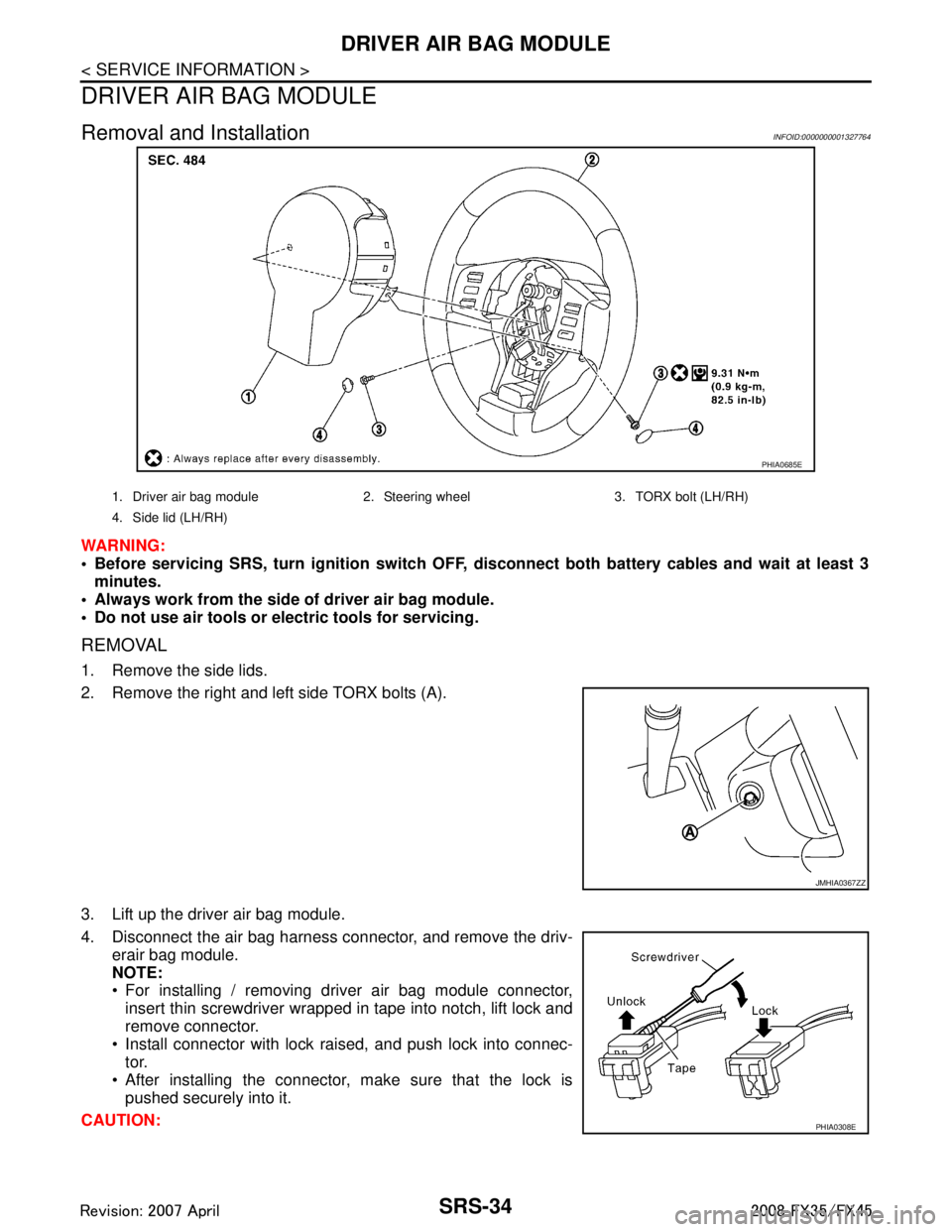
1. Remove the side lids.
2. Remove the right and left side TORX bolts (A).
3. Lift up the driver air bag module.
4. Disconnect the air bag harness connector, and remove the driv-
erair bag module.
NOTE:
For installing / removing driver air bag module connector,insert thin screwdriver wrapped in tape into notch, lift lock and
remove connector.
Install connector with lock raised, and push lock into connec- tor.
After installing the connector, make sure that the lock is pushed securely into it.
CAUTION:
PHIA0685E
1. Driver air bag module 2. Steering wheel 3. TORX bolt (LH/RH)
4. Side lid (LH/RH)
JMHIA0367ZZ
PHIA0308E
3AA93ABC3ACD3AC03ACA3AC03AC63AC53A913A773A893A873A873A8E3A773A983AC73AC93AC03AC3
3A893A873A873A8F3A773A9D3AAF3A8A3A8C3A863A9D3AAF3A8B3A8C
Page 3774 of 3924
SPIRAL CABLESRS-37
< SERVICE INFORMATION >
C
DE
F
G
I
J
K L
M A
B
SRS
N
O P
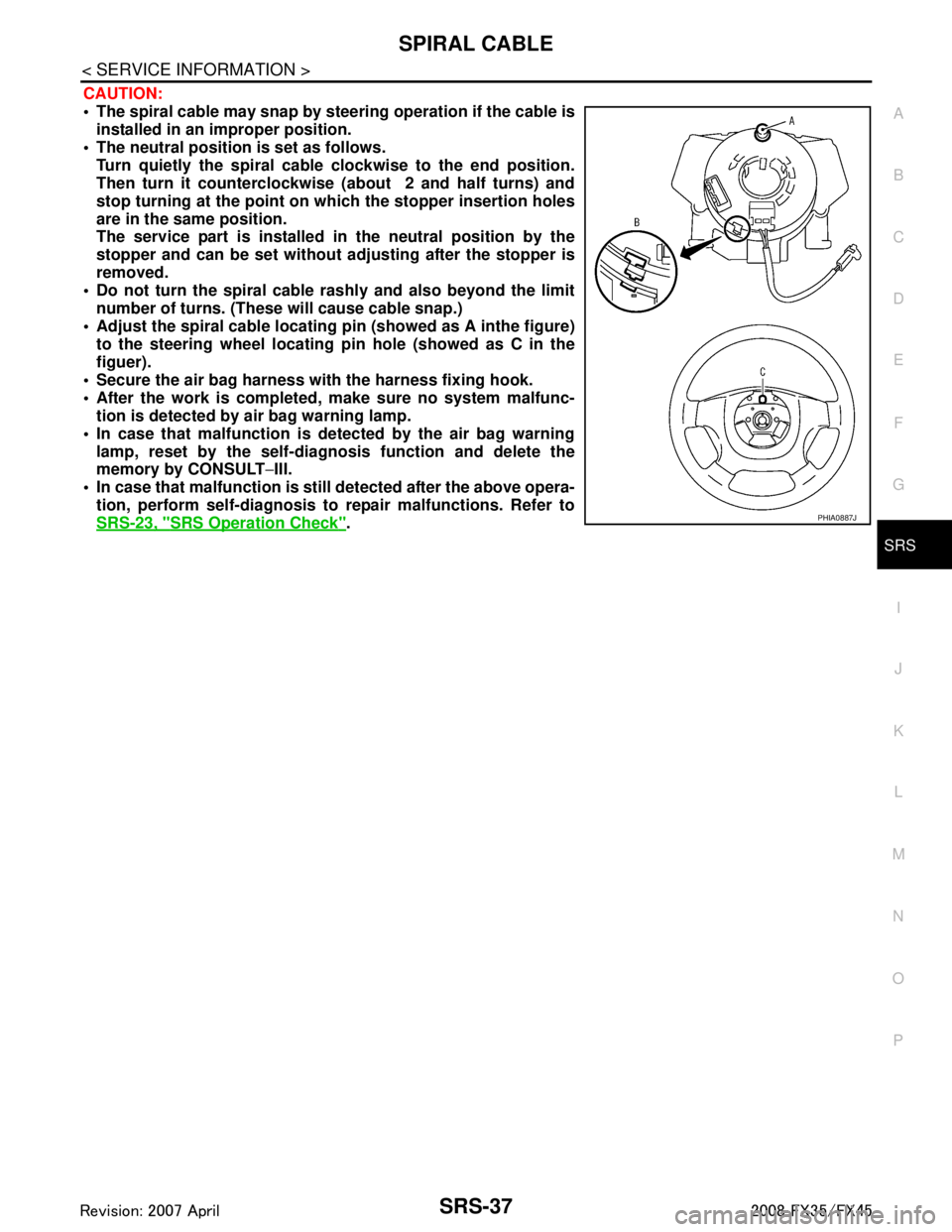
CAUTION:
The spiral cable may snap by steering operation if the cable is
installed in an improper position.
The neutral position is set as follows. Turn quietly the spiral cable clockwise to the end position.
Then turn it counterclockwise (about 2 and half turns) and
stop turning at the point on which the stopper insertion holes
are in the same position.
The service part is installed in the neutral position by the
stopper and can be set without adjusting after the stopper is
removed.
Do not turn the spiral cable r ashly and also beyond the limit
number of turns. (These will cause cable snap.)
Adjust the spiral cable locating pin (showed as A inthe figure) to the steering wheel locating pin hole (showed as C in the
figuer).
Secure the air bag harness wi th the harness fixing hook.
After the work is completed, make sure no system malfunc- tion is detected by air bag warning lamp.
In case that malfunction is detected by the air bag warning lamp, reset by the self-diagnosis function and delete the
memory by CONSULT −III.
In case that malfunction is still detected after the above opera-
tion, perform self-diagnosis to repair malfunctions. Refer to
SRS-23, "
SRS Operation Check".PHIA0887J
3AA93ABC3ACD3AC03ACA3AC03AC63AC53A913A773A893A873A873A8E3A773A983AC73AC93AC03AC3
3A893A873A873A8F3A773A9D3AAF3A8A3A8C3A863A9D3AAF3A8B3A8C
Page 3777 of 3924
SRS-40
< SERVICE INFORMATION >
SIDE CURTAIN AIR BAG MODULE
SIDE CURTAIN AIR BAG MODULE
Removal and InstallationINFOID:0000000001327767
WARNING:
Before servicing SRS, turn ignition switch OFF, disconnect both ba ttery cables and wait at least 3
minutes.
Always work from the side of th e side curtain air bag module.
Do not use air tools or el ectric tools for servicing.
REMOVAL
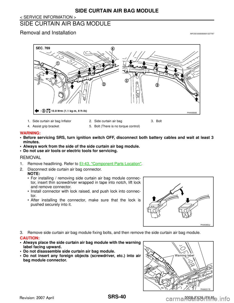
1. Remove headlining. Refer to EI-43, "Component Parts Location".
2. Disconnect side curtain air bag connector. NOTE:
For installing / removing side curtain air bag module connec-
tor, insert thin screwdriver wrapped in tape into notch, lift lock
and remove connector.
Install connector with lock raised, and push lock into connec- tor.
After installing the connector, make sure that the lock is
pushed securely into it.
3. Remove side curtain air bag module fixing bolts, and then remove the side curtain air bag module.
CAUTION:
Always place the side curtain ai r bag module with the warning
label facing upward.
Do not disassemble side cu rtain air bag module.
Do not insert any foreign object s (screwdriver, etc.) into air
bag module connector.
1. Side curtain air bag Inflator 2. Side curtain air bag 3. Bolt
4. Assist grip bracket 5. Bolt (There is no torque control)
PHIA0656E
PHIA0953J
PHIA0317E
3AA93ABC3ACD3AC03ACA3AC03AC63AC53A913A773A893A873A873A8E3A773A983AC73AC93AC03AC3
3A893A873A873A8F3A773A9D3AAF3A8A3A8C3A863A9D3AAF3A8B3A8C
Page 3794 of 3924
TF-8
< SERVICE INFORMATION >
PREPARATION
Tool nameDescription
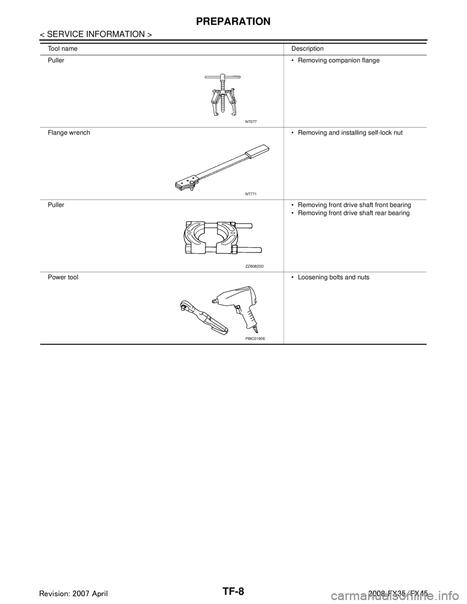
Puller Removing companion flange
Flange wrench Removing and installing self-lock nut
Puller Removing front drive shaft front bearing
Removing front drive shaft rear bearing
Power tool Loosening bolts and nuts
NT077
NT771
ZZB0823D
PBIC0190E
3AA93ABC3ACD3AC03ACA3AC03AC63AC53A913A773A893A873A873A8E3A773A983AC73AC93AC03AC3
3A893A873A873A8F3A773A9D3AAF3A8A3A8C3A863A9D3AAF3A8B3A8C
Page 3809 of 3924
TROUBLE DIAGNOSISTF-23
< SERVICE INFORMATION >
CEF
G H
I
J
K L
M A
B
TF
N
O P
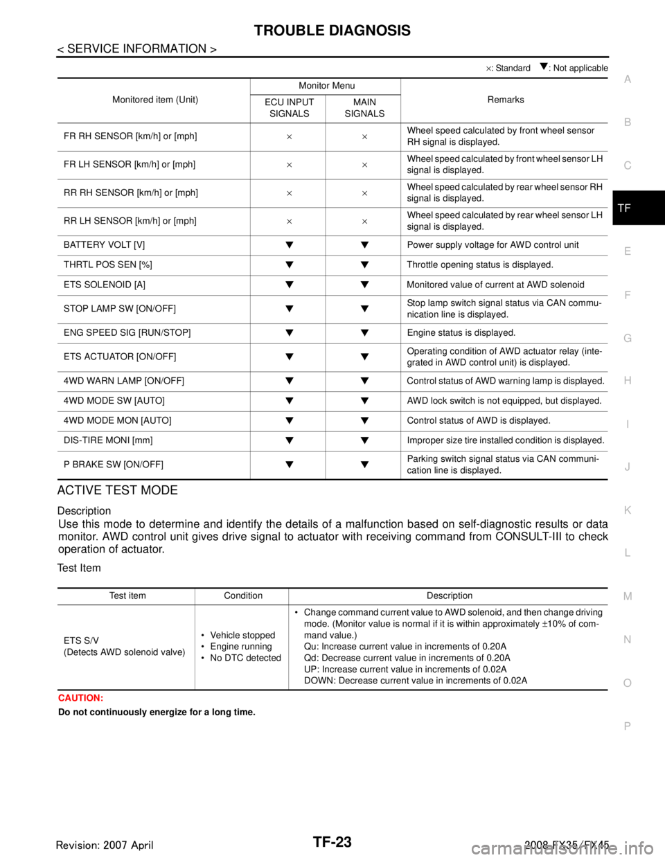
× : Standard : Not applicable
ACTIVE TEST MODE
Description
Use this mode to determine and identify the details of a malfunction based on self-diagnostic results or data
monitor. AWD control unit gives drive signal to actuat or with receiving command from CONSULT-III to check
operation of actuator.
Test Item
CAUTION:
Do not continuously energize for a long time.
Monitored item (Unit) Monitor Menu
Remarks
ECU INPUT
SIGNALS MAIN
SIGNALS
FR RH SENSOR [km/h] or [mph] ××Wheel speed calculated by front wheel sensor
RH signal is displayed.
FR LH SENSOR [km/h] or [mph] ××Wheel speed calculated by front wheel sensor LH
signal is displayed.
RR RH SENSOR [km/h] or [mph] ××Wheel speed calculated by rear wheel sensor RH
signal is displayed.
RR LH SENSOR [km/h] or [mph] ××Wheel speed calculated by rear wheel sensor LH
signal is displayed.
BATTERY VOLT [V] Power supply voltage for AWD control unit
THRTL POS SEN [%] Throttle opening status is displayed.
ETS SOLENOID [A] Monitored value of current at AWD solenoid
STOP LAMP SW [ON/OFF] Stop lamp switch signal status via CAN commu-
nication line is displayed.
ENG SPEED SIG [RUN/STOP] Eng ine status is displayed.
ETS ACTUATOR [ON/OFF] Operating condition of AWD actuator relay (inte-
grated in AWD control unit) is displayed.
4WD WARN LAMP [ON/OFF] Control status of AWD warning lamp is displayed.
4WD MODE SW [AUTO] AWD lock switch is not equipped, but displayed.
4WD MODE MON [AUTO] Control status of AWD is displayed.
DIS-TIRE MONI [mm] Improper size tire installed condition is displayed.
P BRAKE SW [ON/OFF] Parking switch signal status via CAN communi-
cation line is displayed.
Test item Condition Description
ETS S/V
(Detects AWD solenoid valve) Vehicle stopped
Engine running
No DTC detected Change command current value to AWD solenoid, and then change driving
mode. (Monitor value is normal if it is within approximately ±10% of com-
mand value.)
Qu: Increase current value in increments of 0.20A
Qd: Decrease current value in increments of 0.20A
UP: Increase current value in increments of 0.02A
DOWN: Decrease current value in increments of 0.02A
3AA93ABC3ACD3AC03ACA3AC03AC63AC53A913A773A893A873A873A8E3A773A983AC73AC93AC03AC3
3A893A873A873A8F3A773A9D3AAF3A8A3A8C3A863A9D3AAF3A8B3A8C
Page 3811 of 3924
TROUBLE DIAGNOSIS FOR SYSTEMTF-25
< SERVICE INFORMATION >
CEF
G H
I
J
K L
M A
B
TF
N
O P
DTC C1204 4WD SOLENOIDINFOID:0000000001327446
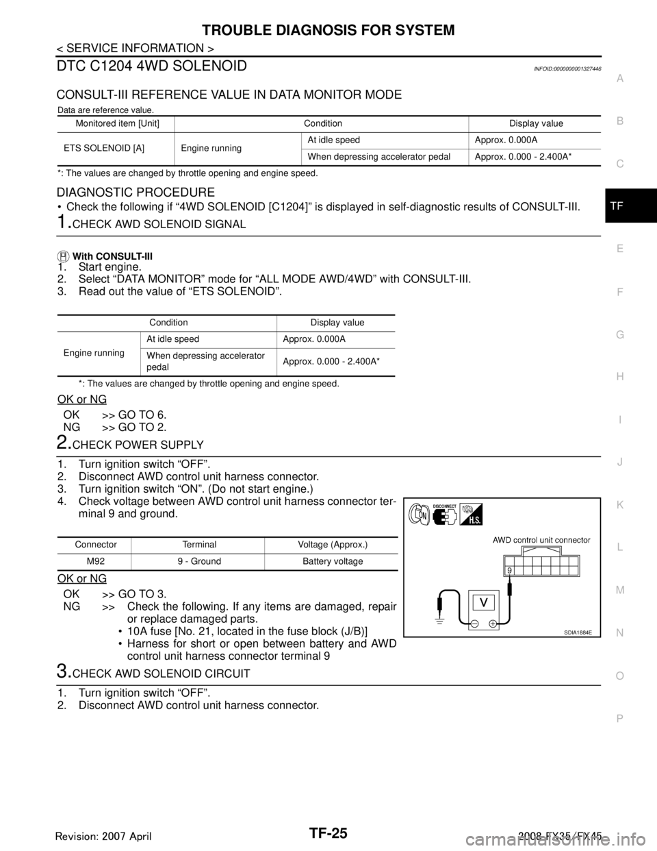
CONSULT-III REFERENCE VALUE IN DATA MONITOR MODE
Data are reference value.
*: The values are changed by throttle opening and engine speed.
DIAGNOSTIC PROCEDURE
Check the following if “4WD SOLENOID [C1204]” is di splayed in self-diagnostic results of CONSULT-III.
1.CHECK AWD SOLENOID SIGNAL
With CONSULT-III
1. Start engine.
2. Select “DATA MONITOR” mode for “A LL MODE AWD/4WD” with CONSULT-III.
3. Read out the value of “ETS SOLENOID”.
*: The values are changed by throttle opening and engine speed.
OK or NG
OK >> GO TO 6.
NG >> GO TO 2.
2.CHECK POWER SUPPLY
1. Turn ignition switch “OFF”.
2. Disconnect AWD control unit harness connector.
3. Turn ignition switch “ON”. (Do not start engine.)
4. Check voltage between AWD control unit harness connector ter- minal 9 and ground.
OK or NG
OK >> GO TO 3.
NG >> Check the following. If any items are damaged, repair or replace damaged parts.
10A fuse [No. 21, located in the fuse block (J/B)]
Harness for short or open between battery and AWD control unit harness connector terminal 9
3.CHECK AWD SOLENOID CIRCUIT
1. Turn ignition switch “OFF”.
2. Disconnect AWD control unit harness connector.
Monitored item [Unit] Condition Display value
ETS SOLENOID [A] Engine running At idle speed Approx. 0.000A
When depressing accelerator pedal Approx. 0.000 - 2.400A*
Condition Display value
Engine running At idle speed Approx. 0.000A
When depressing accelerator
pedal
Approx. 0.000 - 2.400A*
Connector Terminal Voltage (Approx.)
M92 9 - Ground Battery voltage
SDIA1884E
3AA93ABC3ACD3AC03ACA3AC03AC63AC53A913A773A893A873A873A8E3A773A983AC73AC93AC03AC3
3A893A873A873A8F3A773A9D3AAF3A8A3A8C3A863A9D3AAF3A8B3A8C