2008 INFINITI FX35 lock
[x] Cancel search: lockPage 3678 of 3924
![INFINITI FX35 2008 Service Manual
AUTOMATIC DRIVE POSITIONERSE-39
< SERVICE INFORMATION >
C
DE
F
G H
J
K L
M A
B
SE
N
O P
Check 10A fuse [No.9, loca ted in fuse block (J/B)].
NOTE:
Refer to SE-16, "
Component Parts and Harness Con INFINITI FX35 2008 Service Manual
AUTOMATIC DRIVE POSITIONERSE-39
< SERVICE INFORMATION >
C
DE
F
G H
J
K L
M A
B
SE
N
O P
Check 10A fuse [No.9, loca ted in fuse block (J/B)].
NOTE:
Refer to SE-16, "
Component Parts and Harness Con](/manual-img/42/57017/w960_57017-3677.png)
AUTOMATIC DRIVE POSITIONERSE-39
< SERVICE INFORMATION >
C
DE
F
G H
J
K L
M A
B
SE
N
O P
Check 10A fuse [No.9, loca ted in fuse block (J/B)].
NOTE:
Refer to SE-16, "
Component Parts and Harness Connector Location".
OK or NG
OK >> GO TO 5.
NG >> If fuse is blown out, be sure to eliminate c ause of malfunction before installing new fuse. Refer to
SE-16, "
Component Parts and Harness Connector Location".
5.CHECK POWER SUPPLY CIRCUIT (DRIVER SEAT CONTROL UNIT)
1. Disconnect driver seat control unit connector.
2. Check voltage between driver seat control unit and ground.
OK or NG
OK >> GO TO 6.
NG >> Repair or replace harness between driver seat control unit and fuse block (J/B).
6.CHECK GROUND CIRCUIT (DRIVER SEAT CONTROL UNIT)
1. Turn ignition switch OFF.
2. Check continuity between the dr iver seat control unit connector
B152, B153 terminal16A, 61E and ground.
OK or NG
OK >> GO TO 7.
NG >> Repair or replace harness between driver seat control unit and ground.
7.CHECK POWER SUPPLY CIRCUIT (AUTOMAT IC DRIVE POSITIONER CONTROL UNIT)
1. Disconnect automatic drive positioner control unit connector.
2. Check voltage between automatic drive positioner control unit and ground.
OK or NG
OK >> GO TO 8.
NG >> Repair or replace harness between automatic drive positioner control unit and fuse block (J/B).
8.CHECK GROUND CIRCUIT (AUTOMATIC DRI VE POSITIONER CONTROL UNIT)
ConnectorTerminals (W
ire color)
Ignition
switch Voltage (V)
(Approx.)
(+) (–)
B152 9 (BR) GroundSTART
Battery voltage
B153 1A (R)
OFF
11 A ( R / W )
PIIA5085E
16A (B) – Ground : Continuity should exist.
61E (B/Y) – Ground : Continuity should exist.
PIIA5087E
Connector Terminals (W
ire color)
Ignition
switch Voltage (V)
(Approx.)
(+) (–)
M49 28 (SB) GroundSTART
Battery voltage
M50 34 (L/R)
OFF
39 (W/R)
PIIA5086E
3AA93ABC3ACD3AC03ACA3AC03AC63AC53A913A773A893A873A873A8E3A773A983AC73AC93AC03AC3
3A893A873A873A8F3A773A9D3AAF3A8A3A8C3A863A9D3AAF3A8B3A8C
Page 3681 of 3924

SE-42
< SERVICE INFORMATION >
AUTOMATIC DRIVE POSITIONER
ACTIVE TEST
CAUTION:
During vehicle driving, do not perform active test.
NOTE:
If active test is performed, reset seat memory and key fob interlock drive positioner after performing work.
Display Item List
Check CAN Communication SystemINFOID:0000000001532368
1.PERFORM SELF DIAGNOSTIC
1. Turn ignition switch ON and wait for 2 seconds or more.
2. Check “Self Diagnostic Result” of BCM.
TILT SW-UP “ON/OFF” ON/OFF status judged from the tilt switch (UP) signal is displayed.
TILT SW-DOWN “ON/OFF” ON/OFF status judged from the tilt switch (DOWN) signal is displayed.
SET SW “ON/OFF” ON/OFF status judged from the setting switch signal is displayed.
MEMORY SW1 “ON/OFF” ON/OFF status judged from th e seat memory switch 1 signal is displayed.
MEMORY SW2 “ON/OFF” ON/OFF status judged from th e seat memory switch 2 signal is displayed.
P POSI SW “ON/OFF” The selector lever position “ON (P position) / OFF (other than P position)” judged
from the park position switch signal is displayed.
STARTER SW “ON/OFF” Ignition key switch ON (START, ON) /OFF (ignition switch IGN, ACC, or OFF) sta-
tus judged from the ignition switch signal is displayed.
SLIDE PULSE — Value (32768) when battery connects is as standard. If it moves backward, the val-
ue increases. If it moves forward, the value decreases.
RECLN RULSE — Value (32768) when battery connects is as standard. If it moves backward, the val-
ue increases. If it moves forward, the value decreases.
LIFT FR PULSE — Value (32768) when battery connects is as standard. If it moves DOWN, the value
increases. If it moves UP, the value decreases.
LIFT RR PULSE — Value (32768) when battery connects is as standard. If it moves DOWN, the value
increases. If it moves UP, the value decreases.
TILT SEN “V” The tilt position (voltage) judged from the tilt sensor signal is displayed.
TELESCO SEN “V” The telescoping position (voltage) judged from the telescoping sensor signal is dis-
played.
MIR/SE RH R–L “V” Voltage output from RH do or mirror sensor (LH/RH) is displayed.
MIR/SE RH U–D “V” Voltage output from RH door mirror sensor (UP/DOWN) is displayed.
MIR/SE LH R–L “V” Voltage output from LH door mirror sensor (LH/RH) is displayed.
MIR/SE LH U–D “V” Voltage output from LH door mirror sensor (UP/DOWN) is displayed. Monitor item [OPERAT
ION or UNIT] Contents
Test item Description
TILT MOTOR The tilt motor is activated by receiving the drive signal.
TELESCO MOTOR The telescopic motor is activated by receiving the drive signal.
SEAT SLIDE The sliding motor is activated by receiving the drive signal.
SEAT RECLINING The reclining motor is activated by receiving the drive signal.
SEAT LIFTER FR The front end lifter motor is activated by receiving the drive signal.
SEAT LIFTER RR The rear end lifter motor is activated by receiving the drive signal.
MEMORY SW INDCTR The memory sw itch indicator is lit by receivin g the drive signal.
MIRROR MOTOR RH The RH mirror motor moves the mirror UP/DOW
N and LEFT/RIGHT by receiving the drive
signal.
MIRROR MOTOR LH The LH mirror motor moves the mirror UP/DOW
N and LEFT/RIGHT by receiving the drive
signal.
3AA93ABC3ACD3AC03ACA3AC03AC63AC53A913A773A893A873A873A8E3A773A983AC73AC93AC03AC3
3A893A873A873A8F3A773A9D3AAF3A8A3A8C3A863A9D3AAF3A8B3A8C
Page 3716 of 3924
AUTOMATIC DRIVE POSITIONERSE-77
< SERVICE INFORMATION >
C
DE
F
G H
J
K L
M A
B
SE
N
O P
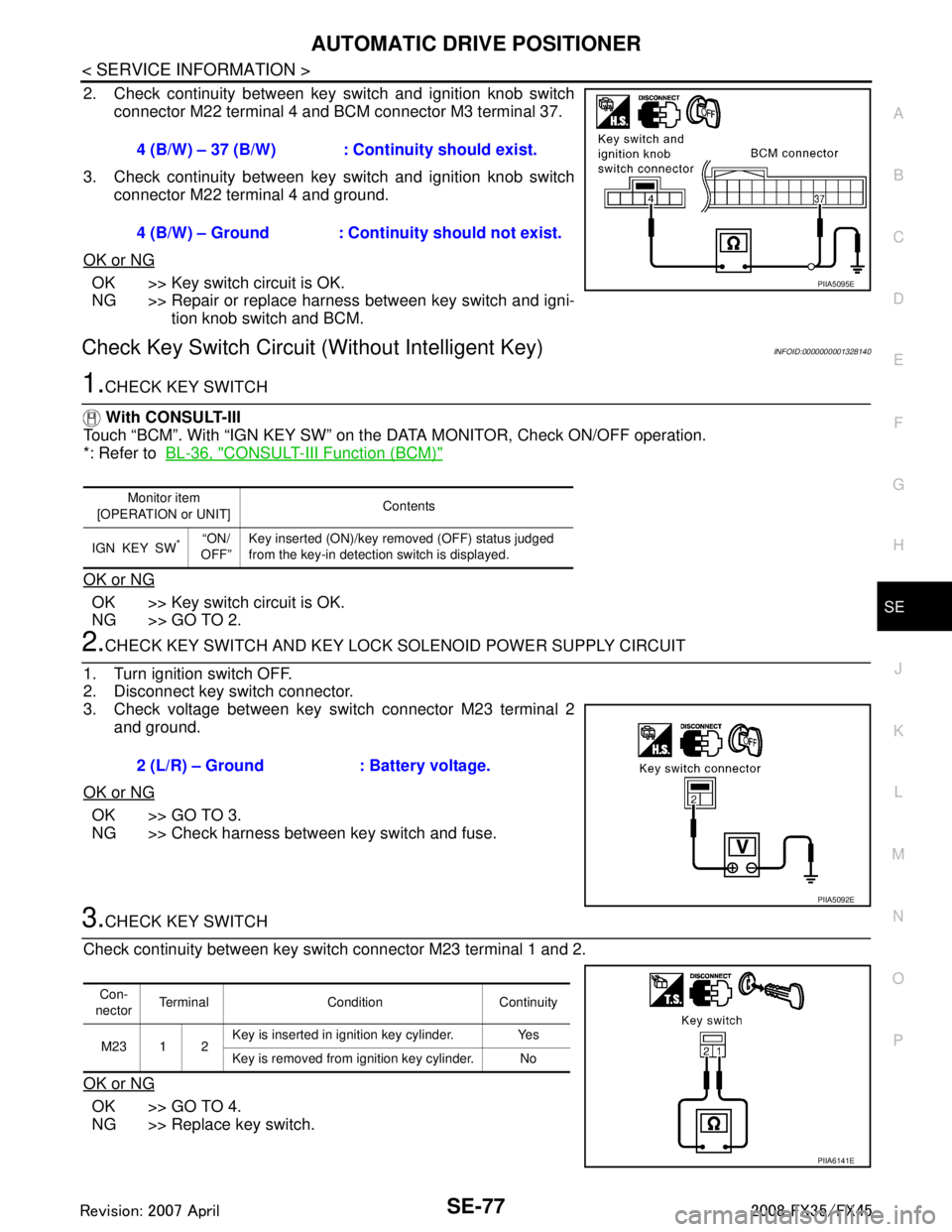
2. Check continuity between key switch and ignition knob switch connector M22 terminal 4 and BCM connector M3 terminal 37.
3. Check continuity between key switch and ignition knob switch connector M22 terminal 4 and ground.
OK or NG
OK >> Key switch circuit is OK.
NG >> Repair or replace harness between key switch and igni- tion knob switch and BCM.
Check Key Switch Circui t (Without Intelligent Key)INFOID:0000000001328140
1.CHECK KEY SWITCH
With CONSULT-III
Touch “BCM”. With “IGN KEY SW” on the DATA MONITOR, Check ON/OFF operation.
*: Refer to BL-36, "
CONSULT-III Function (BCM)"
OK or NG
OK >> Key switch circuit is OK.
NG >> GO TO 2.
2.CHECK KEY SWITCH AND KEY LOCK SOLENOID POWER SUPPLY CIRCUIT
1. Turn ignition switch OFF.
2. Disconnect key switch connector.
3. Check voltage between key switch connector M23 terminal 2 and ground.
OK or NG
OK >> GO TO 3.
NG >> Check harness between key switch and fuse.
3.CHECK KEY SWITCH
Check continuity between key switch connector M23 terminal 1 and 2.
OK or NG
OK >> GO TO 4.
NG >> Replace key switch. 4 (B/W) – 37 (B/W) : Cont
inuity should exist.
4 (B/W) – Ground : Continuity should not exist.
PIIA5095E
Monitor item
[OPERATION or UNIT] Contents
IGN KEY SW
*“ON/
OFF” Key inserted (ON)/key removed (OFF) status judged
from the key-in detection switch is displayed.
2 (L/R) – Ground : Battery voltage.
PIIA5092E
Con-
nector Terminal Condition Continuity
M23 1 2 Key is inserted in ignition key cylinder. Yes
Key is removed from ignition key cylinder. No
PIIA6141E
3AA93ABC3ACD3AC03ACA3AC03AC63AC53A913A773A893A873A873A8E3A773A983AC73AC93AC03AC3
3A893A873A873A8F3A773A9D3AAF3A8A3A8C3A863A9D3AAF3A8B3A8C
Page 3719 of 3924
SE-80
< SERVICE INFORMATION >
AUTOMATIC DRIVE POSITIONER
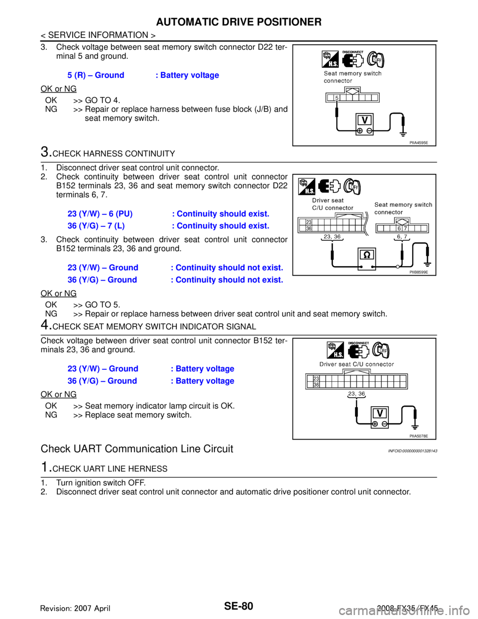
3. Check voltage between seat memory switch connector D22 ter-minal 5 and ground.
OK or NG
OK >> GO TO 4.
NG >> Repair or replace harness between fuse block (J/B) and seat memory switch.
3.CHECK HARNESS CONTINUITY
1. Disconnect driver seat control unit connector.
2. Check continuity between driv er seat control unit connector
B152 terminals 23, 36 and seat memory switch connector D22
terminals 6, 7.
3. Check continuity between driv er seat control unit connector
B152 terminals 23, 36 and ground.
OK or NG
OK >> GO TO 5.
NG >> Repair or replace harness between driver seat control unit and seat memory switch.
4.CHECK SEAT MEMORY SWITCH INDICATOR SIGNAL
Check voltage between driver seat control unit connector B152 ter-
minals 23, 36 and ground.
OK or NG
OK >> Seat memory indicator lamp circuit is OK.
NG >> Replace seat memory switch.
Check UART Communication Line CircuitINFOID:0000000001328143
1.CHECK UART LINE HERNESS
1. Turn ignition switch OFF.
2. Disconnect driver seat control unit connector and automatic drive positioner control unit connector.
5 (R) – Ground : Battery voltage
PIIA4595E
23 (Y/W) – 6 (PU) : Continuity should exist.
36 (Y/G) – 7 (L) : Continuity should exist.
23 (Y/W) – Ground : Continuity should not exist.
36 (Y/G) – Ground : Continuity should not exist.
PIIB8599E
23 (Y/W) – Ground : Battery voltage
36 (Y/G) – Ground : Battery voltage
PIIA5078E
3AA93ABC3ACD3AC03ACA3AC03AC63AC53A913A773A893A873A873A8E3A773A983AC73AC93AC03AC3
3A893A873A873A8F3A773A9D3AAF3A8A3A8C3A863A9D3AAF3A8B3A8C
Page 3721 of 3924
SE-82
< SERVICE INFORMATION >
AUTOMATIC DRIVE POSITIONER
When voltage signal dose not appear with a constant voltage (approx. 5V), replace automatic
driver seat control unit.
When voltage signal dose not appear with a constant voltage (approx. 0V), replace driver seat
control unit.
4.CHECK DRIVER SEAT CONTROL UNIT
Dose the automatic drive positioner operate, when the driver seat control unit exchanged?
Does seat memory function operate?
YES >> Replace automatic drive positioner control unit.
NG >> Replace driver seat control unit.
Check Lumbar Support CircuitINFOID:0000000001328144
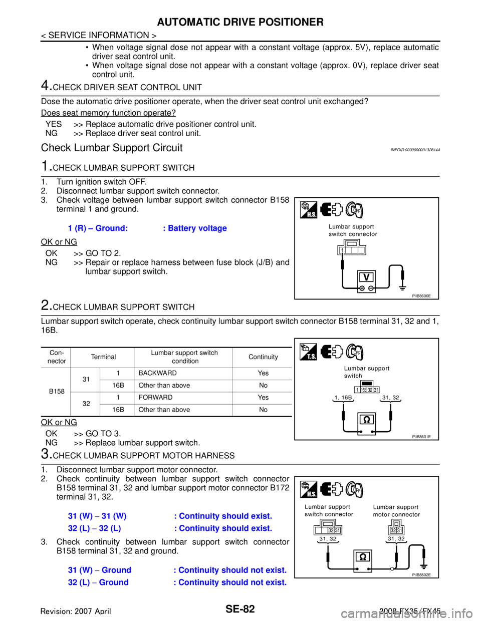
1.CHECK LUMBAR SUPPORT SWITCH
1. Turn ignition switch OFF.
2. Disconnect lumbar support switch connector.
3. Check voltage between lumbar support switch connector B158 terminal 1 and ground.
OK or NG
OK >> GO TO 2.
NG >> Repair or replace harness between fuse block (J/B) and lumbar support switch.
2.CHECK LUMBAR SUPPORT SWITCH
Lumbar support switch operate, check continuity lum bar support switch connector B158 terminal 31, 32 and 1,
16B.
OK or NG
OK >> GO TO 3.
NG >> Replace lumbar support switch.
3.CHECK LUMBAR SUPPORT MOTOR HARNESS
1. Disconnect lumbar support motor connector.
2. Check continuity between lumbar support switch connector B158 terminal 31, 32 and lumbar support motor connector B172
terminal 31, 32.
3. Check continuity between lumbar support switch connector B158 terminal 31, 32 and ground.1 (R) – Ground: : Battery voltage
PIIB8600E
Con-
nector Te r m i n a l
Lumbar support switch
condition Continuity
B158 31
1 BACKWARD Yes
16B Other than above No
32 1FORWARD Yes
16B Other than above No
PIIB8601E
31 (W) − 31 (W) : Continuity should exist.
32 (L) − 32 (L) : Continuity should exist.
31 (W) − Ground : Continuity should not exist.
32 (L) − Ground : Continuity should not exist.
PIIB8602E
3AA93ABC3ACD3AC03ACA3AC03AC63AC53A913A773A893A873A873A8E3A773A983AC73AC93AC03AC3
3A893A873A873A8F3A773A9D3AAF3A8A3A8C3A863A9D3AAF3A8B3A8C
Page 3729 of 3924
SE-90
< SERVICE INFORMATION >
FRONT SEAT
REMOVAL
When removing or installing the seat trim, carefully handle it to keep dirt out and avoid damage.
CAUTION:
Before removing the front seat, turn ignition switch OFF, disconnect both battery cables and wait at
least 3 minutes.
When checking the power seat circuit for continuity using a circuit tester, do not confuse its connec-
tor with the side air bag modul e connector. Such an error may cause the air bag to deploy.
Do not drop, tilt, or bump the side air bag module installing in the seat. Always handle it with care.
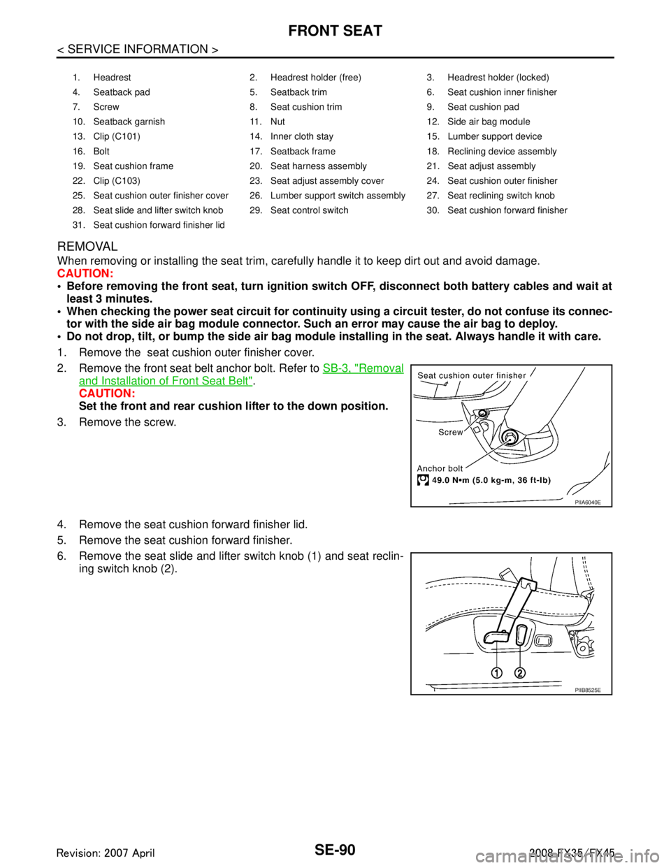
1. Remove the seat cushion outer finisher cover.
2. Remove the front seat belt anchor bolt. Refer to SB-3, "
Removal
and Installation of Front Seat Belt".
CAUTION:
Set the front and rear cushion lifter to the down position.
3. Remove the screw.
4. Remove the seat cushion forward finisher lid.
5. Remove the seat cushion forward finisher.
6. Remove the seat slide and lifter switch knob (1) and seat reclin- ing switch knob (2).
1. Headrest 2. Headrest holder (free) 3. Headrest holder (locked)
4. Seatback pad 5. Seatback trim 6. Seat cushion inner finisher
7. Screw 8. Seat cushion trim 9. Seat cushion pad
10. Seatback garnish 11. Nut 12. Side air bag module
13. Clip (C101) 14. Inner cloth stay 15. Lumber support device
16. Bolt 17. Seatback frame 18. Reclining device assembly
19. Seat cushion frame 20. Seat harness assembly 21. Seat adjust assembly
22. Clip (C103) 23. Seat adjust assembly cover 24. Seat cushion outer finisher
25. Seat cushion outer finisher cover 26. Lumber support switch assembly 27. Seat reclining switch knob
28. Seat slide and lifter switch knob 29. Seat control switch 30. Seat cushion forward finisher
31. Seat cushion forward finisher lid
PIIA6040E
PIIB8525E
3AA93ABC3ACD3AC03ACA3AC03AC63AC53A913A773A893A873A873A8E3A773A983AC73AC93AC03AC3
3A893A873A873A8F3A773A9D3AAF3A8A3A8C3A863A9D3AAF3A8B3A8C
Page 3734 of 3924
REAR SEATSE-95
< SERVICE INFORMATION >
C
DE
F
G H
J
K L
M A
B
SE
N
O P
REAR SEAT
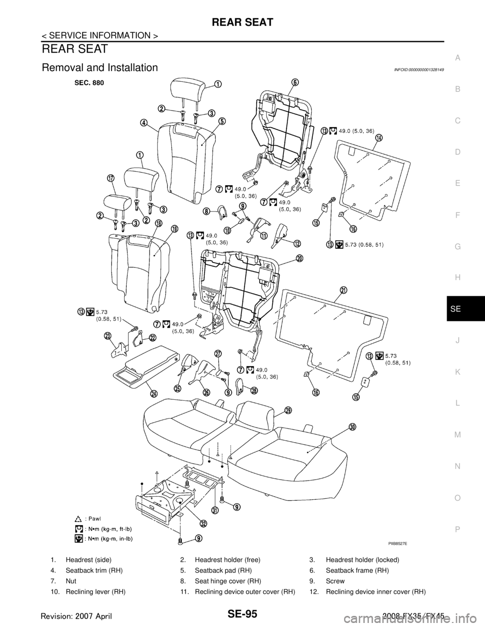
Removal and InstallationINFOID:0000000001328149
PIIB8527E
1. Headrest (side) 2. Headrest holder (free) 3. Headrest holder (locked)
4. Seatback trim (RH) 5. Seatback pad (RH) 6. Seatback frame (RH)
7. Nut 8. Seat hinge cover (RH) 9. Screw
10. Reclining lever (RH) 11. Reclining device outer cover (RH) 12. Reclining device inner cover (RH)
3AA93ABC3ACD3AC03ACA3AC03AC63AC53A913A773A893A873A873A8E3A773A983AC73AC93AC03AC3
3A893A873A873A8F3A773A9D3AAF3A8A3A8C3A863A9D3AAF3A8B3A8C
Page 3735 of 3924
SE-96
< SERVICE INFORMATION >
REAR SEAT
REMOVAL
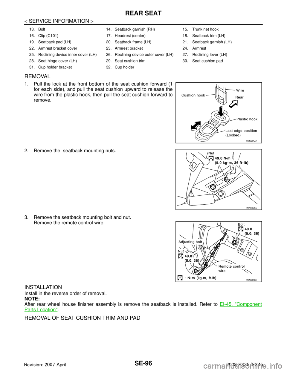
1. Pull the lock at the front bottom of the seat cushion forward (1
for each side), and pull the seat cushion upward to release the
wire from the plastic hook, then pull the seat cushion forward to
remove.
2. Remove the seatback mounting nuts.
3. Remove the seatback mounting bolt and nut. Remove the remote control wire.
INSTALLATION
Install in the reverse order of removal.
NOTE:
After rear wheel house finisher assembly is remove the seatback is installed. Refer to EI-45, "
Component
Parts Location".
REMOVAL OF SEAT CUSHION TRIM AND PAD
13. Bolt 14. Seatback garnish (RH) 15. Trunk net hook
16. Clip (C101) 17. Headrest (center) 18. Seatback trim (LH)
19. Seatback pad (LH) 20. Seatback frame (LH) 21. Seatback garnish (LH)
22. Armrest bracket cover 23. Armrest bracket 24. Armrest
25. Reclining device inner cover (LH) 26. Reclining device outer cover (LH) 27. Reclining lever (LH)
28. Seat hinge cover (LH) 29. Seat cushion trim 30. Seat cushion pad
31. Cup holder bracket 32. Cup holder
PIIA6034E
PIIA6035E
PIIA6036E
3AA93ABC3ACD3AC03ACA3AC03AC63AC53A913A773A893A873A873A8E3A773A983AC73AC93AC03AC3
3A893A873A873A8F3A773A9D3AAF3A8A3A8C3A863A9D3AAF3A8B3A8C