Page 3525 of 3924
RF-10
< SERVICE INFORMATION >
SUNROOF
SUNROOF
Component Parts and Harness Connector LocationINFOID:0000000001328033
System DescriptionINFOID:0000000001328034
Power supplied at all time
through 50A fusible link (letter M, located in the fuse and fusible link box)
to BCM terminal 55.
through 15A fuse [No.22, located in the fuse block (J/B)]
to BCM terminal 42.
through BCM terminal 54
to sunroof motor assembly terminal 7.
When ignition switch ON or START position,
Power is supplied
through 15A fuse [No.1, located in the fuse block (J/B)]
to BCM terminal 38.
through BCM terminal 53
to sunroof motor assembly terminal 9.
Ground is supplied
PIIB8564E
3AA93ABC3ACD3AC03ACA3AC03AC63AC53A913A773A893A873A873A8E3A773A983AC73AC93AC03AC3
3A893A873A873A8F3A773A9D3AAF3A8A3A8C3A863A9D3AAF3A8B3A8C
Page 3531 of 3924
![INFINITI FX35 2008 Service Manual
RF-16
< SERVICE INFORMATION >
SUNROOF
Check BCM Power Suppl y and Ground Circuit
INFOID:0000000001328043
1.CHECK FUSE
Check 15A fuse [No.1, located in the fuse block (J/B)]
Check 15A fuse [No.22, INFINITI FX35 2008 Service Manual
RF-16
< SERVICE INFORMATION >
SUNROOF
Check BCM Power Suppl y and Ground Circuit
INFOID:0000000001328043
1.CHECK FUSE
Check 15A fuse [No.1, located in the fuse block (J/B)]
Check 15A fuse [No.22,](/manual-img/42/57017/w960_57017-3530.png)
RF-16
< SERVICE INFORMATION >
SUNROOF
Check BCM Power Suppl y and Ground Circuit
INFOID:0000000001328043
1.CHECK FUSE
Check 15A fuse [No.1, located in the fuse block (J/B)]
Check 15A fuse [No.22, located in the fuse block (J/B)]
Check 50A fusible link (letter M, located in the fuse and fusible link box).
NOTE:
Refer to RF-10, "
Component Parts and Harness Connector Location".
OK or NG
OK >> GO TO 2.
NG >> If fuse is blown out, be sure to eliminate cause of malfunction before installing new fuse. Refer to RF-10, "
Component Parts and Harness Connector Location".
2.CHECK POWER SUPPLY CIRCUIT
1. Turn ignition switch ON.
2. Check voltage between BCM connector M3, M4 terminal 38, 42, 55 and ground.
OK or NG
OK >> GO TO 3.
NG >> Check BCM power supply circuit for open or short.
3.CHECK GROUND CIRCUIT
1. Turn ignition switch OFF.
2. Disconnect BCM connector.
3. Check continuity between BCM connector M4 terminal 49, 52 and ground.
OK or NG
OK >> Power supply and ground circuit are OK.
NG >> Check BCM ground circuit for open or short.
Check Sunroof Motor Assembly Power Supply and Ground CircuitINFOID:0000000001328044
1.CHECK POWER SUPPLY CIRCUIT
1. Turn ignition switch ON.
2. Check voltage between sunroof motor assembly connector R5 terminal 7, 9 and ground.
Retained power operation does not operate
properly. 1. Check the retained power operation mode setting.
RF-152. Check door switch.RF-19
3. Replace sunroof motor assembly.RF-22
Sunroof does not operate the interruption de-
tection function.Replace sunroof motor assembly.
RF-22
Symptom Diagnostic procedure and repair order Refer to page
38 (W/L) – Ground : Battery voltage
42 (L/R) – Ground : Battery voltage
55 (G) – Ground : Battery voltage
PIIA6160E
49 (B) – Ground : Continuity should exist.
52 (B) – Ground : Continuity should exist.
PIIA6161E
3AA93ABC3ACD3AC03ACA3AC03AC63AC53A913A773A893A873A873A8E3A773A983AC73AC93AC03AC3
3A893A873A873A8F3A773A9D3AAF3A8A3A8C3A863A9D3AAF3A8B3A8C
Page 3548 of 3924
RFD-6
< SERVICE INFORMATION >
PREPARATION
Commercial Service Tool
INFOID:0000000001327492
(J-34309)
Differential shim selector tool Adjusting bearing preload and pinion gear
height
(J-25269-4)
Side bearing disc (2 Req'd) Selecting pinion height adjusting washer
Tool number
(Kent-Moore No.)
Tool name
Description
NT134
NT136
Tool name
Description
Flange wrench Removing and installing drive pinion lock nut
Spacer
a: 60 mm (2.36 in) dia.
b: 36 mm (1.42 in) dia.
c: 30 mm (1.18 in) Installing pinion front bearing inner race
Power tool Loosening nuts and bolts
NT035
ZZA1133D
PBIC0190E
3AA93ABC3ACD3AC03ACA3AC03AC63AC53A913A773A893A873A873A8E3A773A983AC73AC93AC03AC3
3A893A873A873A8F3A773A9D3AAF3A8A3A8C3A863A9D3AAF3A8B3A8C
Page 3553 of 3924

FRONT OIL SEALRFD-11
< SERVICE INFORMATION >
CEF
G H
I
J
K L
M A
B
RFD
N
O P
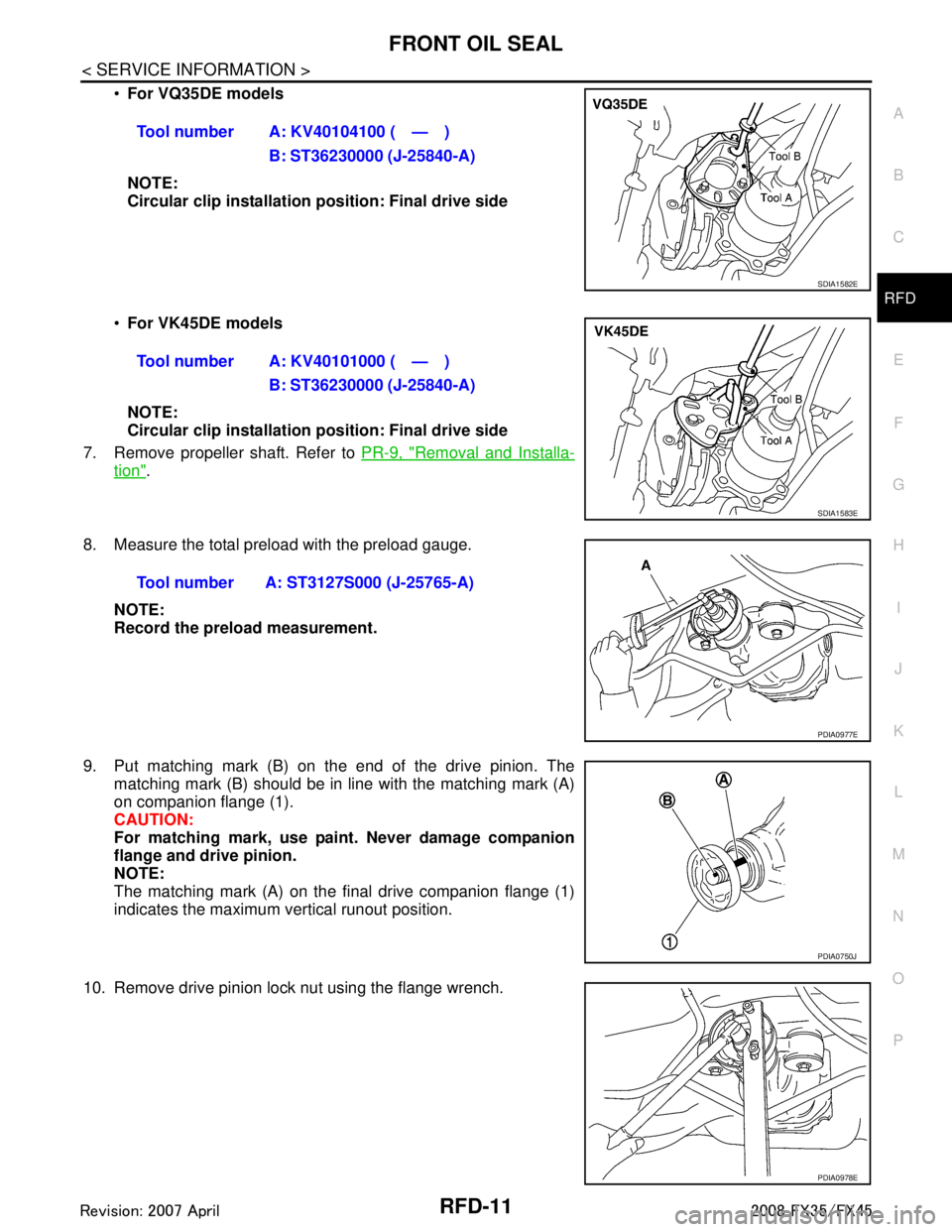
For VQ35DE models
NOTE:
Circular clip installation position: Final drive side
For VK45DE models
NOTE:
Circular clip installation position: Final drive side
7. Remove propeller shaft. Refer to PR-9, "
Removal and Installa-
tion".
8. Measure the total preload with the preload gauge. NOTE:
Record the preload measurement.
9. Put matching mark (B) on the end of the drive pinion. The matching mark (B) should be in line with the matching mark (A)
on companion flange (1).
CAUTION:
For matching mark, use pain t. Never damage companion
flange and drive pinion.
NOTE:
The matching mark (A) on the final drive companion flange (1)
indicates the maximum vertical runout position.
10. Remove drive pinion lock nut using the flange wrench. Tool number A: KV40104100 ( — )
B: ST36230000 (J-25840-A)
SDIA1582E
Tool number A: KV40101000 ( — )B: ST36230000 (J-25840-A)
SDIA1583E
Tool number A: ST3127S000 (J-25765-A)
PDIA0977E
PDIA0750J
PDIA0978E
3AA93ABC3ACD3AC03ACA3AC03AC63AC53A913A773A893A873A873A8E3A773A983AC73AC93AC03AC3
3A893A873A873A8F3A773A9D3AAF3A8A3A8C3A863A9D3AAF3A8B3A8C
Page 3554 of 3924
RFD-12
< SERVICE INFORMATION >
FRONT OIL SEAL
11. Remove companion flange using a puller.
12. Remove front oil seal using the puller.
INSTALLATION
1. Apply multi-purpose grease to front oil seal lips.
2. Install front oil seal using the drift as shown in figure.CAUTION:
Never reuse oil seal.
When installing, n ever incline oil seal.
3. Align the matching mark (B) of drive pinion with the matching mark (A) of companion flange (1), and then install the compan-
ion flange (1).
4. Apply anti-corrosion oil to the thread and seat of new drive pinion lock nut, and temporarily tighten drive
pinion lock nut to drive pinion.
CAUTION:
Never reuse drive pinion lock nut.
PDIA0979E
Tool number A: KV381054S0 (J-34286)
PDIA0980E
Tool number A: ST30720000 (J-25405)
PDIA0752J
PDIA0750J
3AA93ABC3ACD3AC03ACA3AC03AC63AC53A913A773A893A873A873A8E3A773A983AC73AC93AC03AC3
3A893A873A873A8F3A773A9D3AAF3A8A3A8C3A863A9D3AAF3A8B3A8C
Page 3555 of 3924

FRONT OIL SEALRFD-13
< SERVICE INFORMATION >
CEF
G H
I
J
K L
M A
B
RFD
N
O P
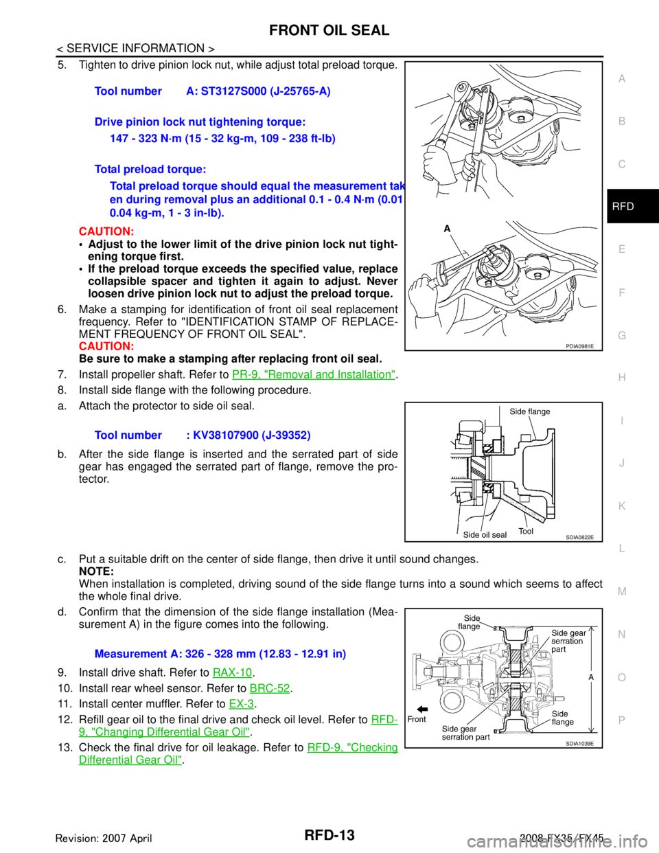
5. Tighten to drive pinion lock nut, while adjust total preload torque.
CAUTION:
Adjust to the lower limit of the drive pinion lock nut tight-
ening torque first.
If the preload torque exceeds the specified value, replace
collapsible spacer and tighte n it again to adjust. Never
loosen drive pinion lock nut to adjust the preload torque.
6. Make a stamping for identificati on of front oil seal replacement
frequency. Refer to "IDENTIFICATION STAMP OF REPLACE-
MENT FREQUENCY OF FRONT OIL SEAL".
CAUTION:
Be sure to make a stamping after replacing front oil seal.
7. Install propeller shaft. Refer to PR-9, "
Removal and Installation".
8. Install side flange with the following procedure.
a. Attach the protector to side oil seal.
b. After the side flange is inserted and the serrated part of side gear has engaged the serrated part of flange, remove the pro-
tector.
c. Put a suitable drift on the center of side flange, then drive it until sound changes.
NOTE:
When installation is completed, driving sound of the side flange turns into a sound which seems to affect
the whole final drive.
d. Confirm that the dimension of the side flange installation (Mea- surement A) in the figure comes into the following.
9. Install drive shaft. Refer to RAX-10
.
10. Install rear wheel sensor. Refer to BRC-52
.
11. Install center muffler. Refer to EX-3
.
12. Refill gear oil to the final drive and check oil level. Refer to RFD-
9, "Changing Differential Gear Oil".
13. Check the final drive for oil leakage. Refer to RFD-9, "
Checking
Differential Gear Oil".
Tool number A: ST3127S000 (J-25765-A)
Drive pinion lock nut tightening torque:
147 - 323 N·m (15 - 32 kg-m, 109 - 238 ft-lb)
Total preload torque: Total preload torque should equal the measurement tak-
en during removal plus an ad ditional 0.1 - 0.4 N·m (0.01 -
0.04 kg-m, 1 - 3 in-lb).
Tool number : KV38107900 (J-39352)
PDIA0981E
SDIA0822E
Measurement A: 326 - 328 mm (12.83 - 12.91 in)
SDIA1039E
3AA93ABC3ACD3AC03ACA3AC03AC63AC53A913A773A893A873A873A8E3A773A983AC73AC93AC03AC3
3A893A873A873A8F3A773A9D3AAF3A8A3A8C3A863A9D3AAF3A8B3A8C
Page 3560 of 3924

RFD-18
< SERVICE INFORMATION >
REAR FINAL DRIVE ASSEMBLY
ASSEMBLY INSPECTION AND ADJUSTMENT
Before inspection and adjustment, drain gear oil.
Total Preload Torque
1. Secure final drive assembly onto an attachment.
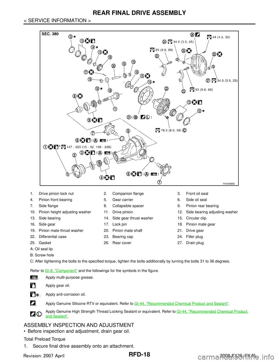
1. Drive pinion lock nut 2. Companion flange 3. Front oil seal
4. Pinion front bearing 5. Gear carrier 6. Side oil seal
7. Side flange 8. Collapsible spacer 9. Pinion rear bearing
10. Pinion height adjusting washer 11. Drive pinion 12. Side bearing adjusting washer
13. Side bearing 14. Side gear thrust washer 15. Circular clip
16. Side gear 17. Lock pin 18. Pinion mate gear
19. Pinion mate thrust washer 20. Pinion mate shaft 21. Drive gear
22. Differential case 23. Bearing cap 24. Filler plug
25. Gasket 26. Rear cover 27. Drain plug
A: Oil seal lip
B: Screw hole
C: After tightening the bolts to the specified torque, tighten the bolts additionally by turning the bolts 31 to 36 degrees.
Refer to GI-8, "
Component" and the followings for the symbols in the figure.
: Apply multi-purpose grease.
: Apply gear oil.
: Apply anti-corrosion oil.
: Apply Genuine Silicone RTV or equivalent. Refer to
GI-44, "
Recommended Chemical Product and Sealant".
: Apply Genuine High Strength Thread Locking Sealant or equivalent. Refer to
GI-44, "
Recommended Chemical Product
and Sealant".
PDIA0986E
3AA93ABC3ACD3AC03ACA3AC03AC63AC53A913A773A893A873A873A8E3A773A983AC73AC93AC03AC3
3A893A873A873A8F3A773A9D3AAF3A8A3A8C3A863A9D3AAF3A8B3A8C
Page 3561 of 3924

REAR FINAL DRIVE ASSEMBLYRFD-19
< SERVICE INFORMATION >
CEF
G H
I
J
K L
M A
B
RFD
N
O P
2. Remove side flanges.
3. Rotate drive pinion back and forth 2 to 3 times to check for unusual noise and rotation malfunction.
4. Rotate drive pinion at least 20 times to check for smooth operation of the bearing.
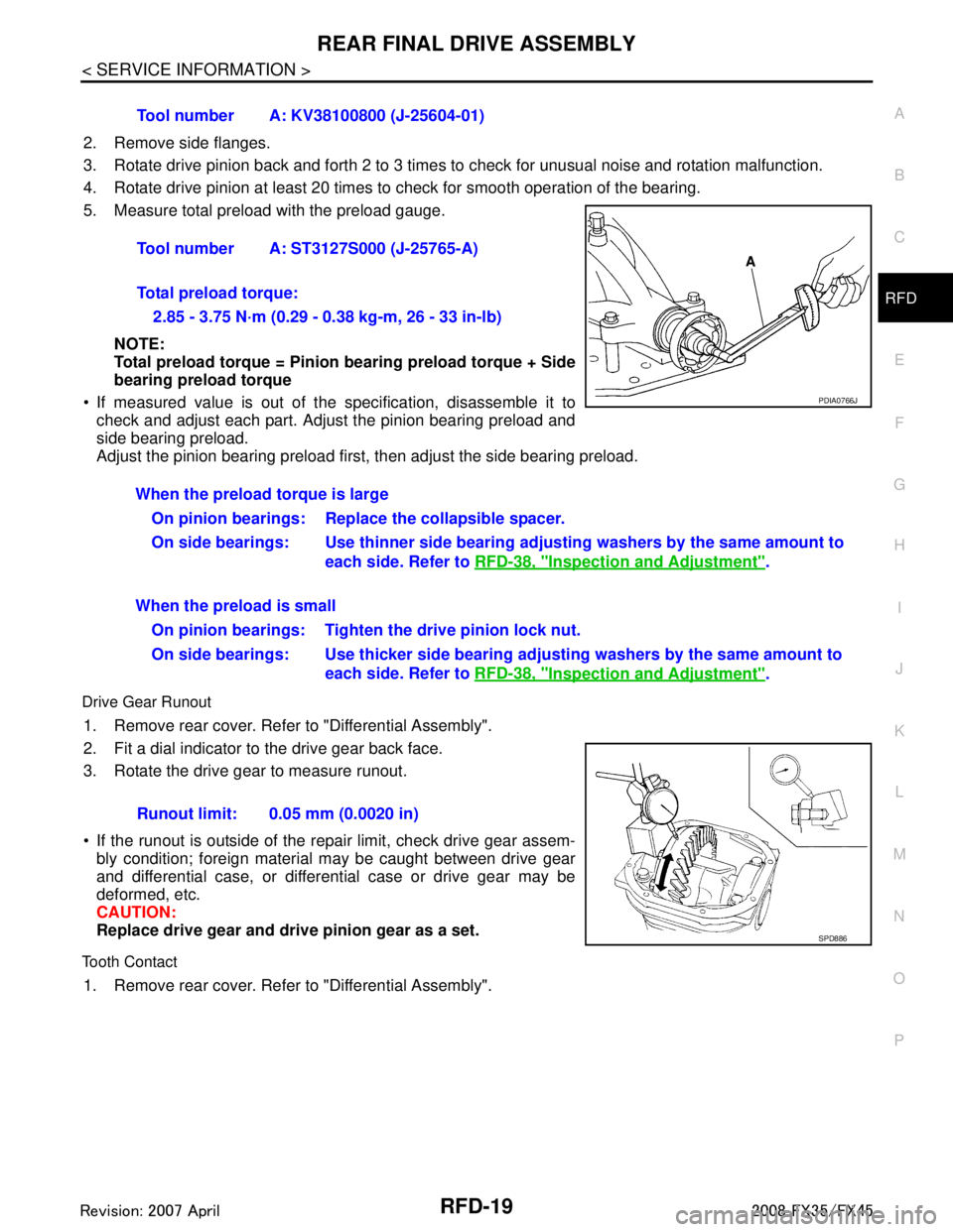
5. Measure total preload with the preload gauge.
NOTE:
Total preload torque = Pinion bearing preload torque + Side
bearing preload torque
If measured value is out of the specification, disassemble it to
check and adjust each part. Adjust the pinion bearing preload and
side bearing preload.
Adjust the pinion bearing preload first, then adjust the side bearing preload.
Drive Gear Runout
1. Remove rear cover. Refer to "Differential Assembly".
2. Fit a dial indicator to the drive gear back face.
3. Rotate the drive gear to measure runout.
If the runout is outside of the repair limit, check drive gear assem- bly condition; foreign material may be caught between drive gear
and differential case, or differential case or drive gear may be
deformed, etc.
CAUTION:
Replace drive gear and dri ve pinion gear as a set.
Tooth Contact
1. Remove rear cover. Refer to "Differential Assembly".Tool number A: KV38100800 (J-25604-01)
Tool number A: ST3127S000 (J-25765-A)
Total preload torque:
2.85 - 3.75 N·m (0.29 - 0.38 kg-m, 26 - 33 in-lb)
PDIA0766J
When the preload torque is largeOn pinion bearings: Replace the collapsible spacer.
On side bearings: Use thinner side bearing adjusting washers by the same amount to
each side. Refer to RFD-38, "
Inspection and Adjustment".
When the preload is small On pinion bearings: Tighten the drive pinion lock nut.
On side bearings: Use thicker side bearing adjusting washers by the same amount to
each side. Refer to RFD-38, "
Inspection and Adjustment".
Runout limit: 0.05 mm (0.0020 in)
SPD886
3AA93ABC3ACD3AC03ACA3AC03AC63AC53A913A773A893A873A873A8E3A773A983AC73AC93AC03AC3
3A893A873A873A8F3A773A9D3AAF3A8A3A8C3A863A9D3AAF3A8B3A8C