2008 INFINITI FX35 display
[x] Cancel search: displayPage 3530 of 3924
SUNROOFRF-15
< SERVICE INFORMATION >
C
DE
F
G H
J
K L
M A
B
RF
N
O P
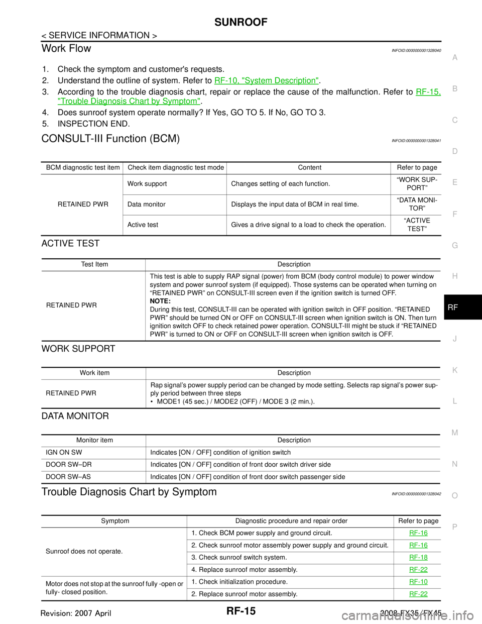
Work FlowINFOID:0000000001328040
1. Check the symptom and customer's requests.
2. Understand the outline of system. Refer to RF-10, "
System Description".
3. According to the trouble diagnosis chart, repair or replace the cause of the malfunction. Refer to RF-15,
"Trouble Diagnosis Chart by Symptom".
4. Does sunroof system operate normally? If Yes, GO TO 5. If No, GO TO 3.
5. INSPECTION END.
CONSULT-III Function (BCM)INFOID:0000000001328041
ACTIVE TEST
WORK SUPPORT
DATA MONITOR
Trouble Diagnosis Chart by SymptomINFOID:0000000001328042
BCM diagnostic test item Check item diagnostic test mode Content Refer to page
RETAINED PWR Work support Changes setting of each function.
“WORK SUP-
PORT”
Data monitor Displays the input data of BCM in real time. “DATA MONI-
TOR”
Active test Gives a drive signal to a load to check the operation. “ACTIVE
TEST”
Test Item Description
RETAINED PWR This test is able to supply RAP signal (powe
r) from BCM (body control module) to power window
system and power sunroof system (if equipped). Those systems can be operated when turning on
“RETAINED PWR” on CONSULT-III screen even if the ignition switch is turned OFF.
NOTE:
During this test, CONSULT-III can be operated with ignition switch in OFF position. “RETAINED
PWR” should be turned ON or OFF on CONSULT-III screen when ignition switch is ON. Then turn
ignition switch OFF to check retained power operation. CONSULT-III might be stuck if “RETAINED
PWR” is turned to ON or OFF on CONSULT- III screen when ignition switch is OFF.
Work item Description
RETAINED PWR Rap signal’s power supply period can be changed by mode setting. Selects rap signal’s power sup-
ply period between three steps
MODE1 (45 sec.) / MODE2 (OFF) / MODE 3 (2 min.).
Monitor item Description
IGN ON SW Indicates [ON / OFF] condition of ignition switch
DOOR SW–DR Indicates [ON / OFF] condition of front door switch driver side
DOOR SW–AS Indicates [ON / OFF] condition of front door switch passenger side
Symptom Diagnostic procedure and repair order Refer to page
Sunroof does not operate. 1. Check BCM power supply and ground circuit.
RF-16
2. Check sunroof motor assembly power supply and ground circuit.RF-16
3. Check sunroof switch system. RF-18
4. Replace sunroof motor assembly.RF-22
Motor does not stop at the sunroof fully -open or
fully- closed position.1. Check initialization procedure.
RF-10
2. Replace sunroof motor assembly.RF-22
3AA93ABC3ACD3AC03ACA3AC03AC63AC53A913A773A893A873A873A8E3A773A983AC73AC93AC03AC3
3A893A873A873A8F3A773A9D3AAF3A8A3A8C3A863A9D3AAF3A8B3A8C
Page 3586 of 3924
REAR SUSPENSION ASSEMBLYRSU-5
< SERVICE INFORMATION >
C
DF
G H
I
J
K L
M A
B
RSU
N
O P
REAR SUSPENSION ASSEMBLY
On-Vehicle Inspection and ServiceINFOID:0000000001327552
Make sure the mounting conditions (looseness, ba ck lash) of each component and component status (wear,
damage) are normal.
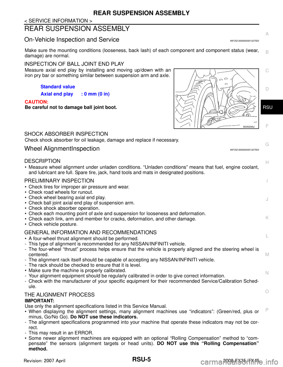
INSPECTION OF BALL JOINT END PLAY
Measure axial end play by installing and moving up/down with an
iron pry bar or something similar between suspension arm and axle.
CAUTION:
Be careful not to damage ball joint boot.
SHOCK ABSORBER INSPECTION
Check shock absorber for oil leakage, damage and replace if necessary.
Wheel AlignmentInspectionINFOID:0000000001327553
DESCRIPTION
Measure wheel alignment under unladen conditions. “U nladen conditions” means that fuel, engine coolant,
and lubricant are full. Spare tire, jack, hand tools and mats in designated positions.
PRELIMINARY INSPECTION
Check tires for improper air pressure and wear.
Check road wheels for runout.
Check wheel bearing axial end play.
Check ball joint axial end play of suspension arm.
Check shock absorber operation.
Check each mounting point of axle and suspension for looseness and deformation.
Check each link, arm and member for cracks, deformation, and other damage.
Check vehicle posture.
GENERAL INFORMATION AND RECOMMENDATIONS
A four-wheel thrust alignment should be performed.
- This type of alignment is recomm ended for any NISSAN/INFINITI vehicle.
- The four-wheel “thrust” process helps ensure that t he vehicle is properly aligned and the steering wheel is
centered.
- The alignment rack itself should be capable of accepting any NISSAN/INFINITI vehicle.
- The rack should be checked to ensure that it is level.
Make sure the machine is properly calibrated.
- Your alignment equipment should be regularly ca librated in order to give correct information.
- Check with the manufacturer of your specific equi pment for their recommended Service/Calibration Sched-
ule.
THE ALIGNMENT PROCESS
IMPORTANT:
Use only the alignment specificati ons listed in this Service Manual.
When displaying the alignment settings, many alignment machines use “indicators”: (Green/red, plus or
minus, Go/No Go). Do NOT use these indicators.
- The alignment specifications programmed into your machine that operate these indicators may not be cor-
rect.
- This may result in an ERROR.
Some newer alignment machines are equipped with an optional “Rolling Compensation” method to “com-
pensate” the sensors (alignment targets or head units). DO NOT use this “Rolling Compensation”
method. Standard value
Axial end play : 0 mm (0 in)
SEIA0245J
3AA93ABC3ACD3AC03ACA3AC03AC63AC53A913A773A893A873A873A8E3A773A983AC73AC93AC03AC3
3A893A873A873A8F3A773A9D3AAF3A8A3A8C3A863A9D3AAF3A8B3A8C
Page 3642 of 3924
DTC INDEXSE-3
< SERVICE INFORMATION >
C
DE
F
G H
J
K L
M A
B
SE
N
O P
SERVICE INFORMATION
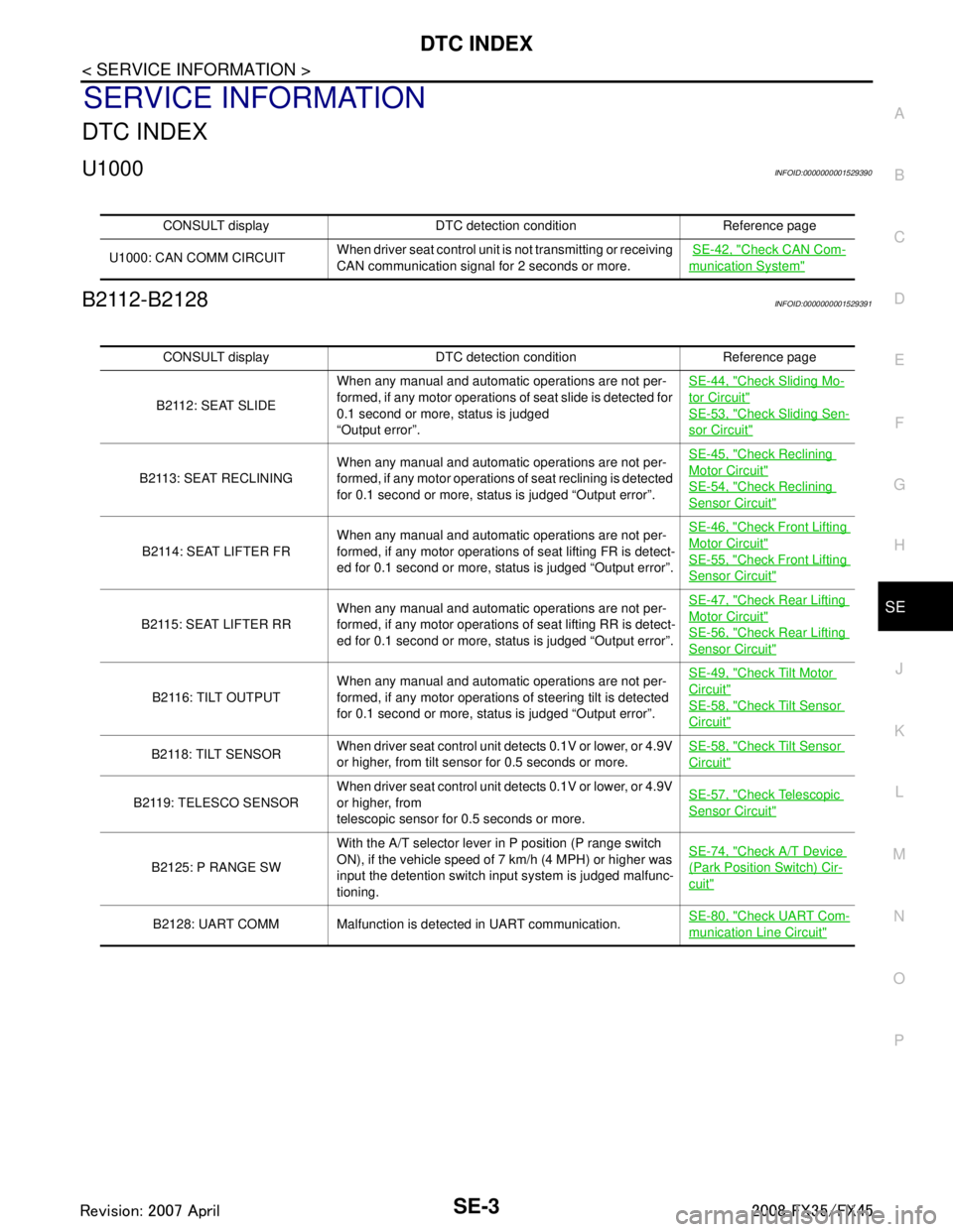
DTC INDEX
U1000INFOID:0000000001529390
B2112-B2128INFOID:0000000001529391
CONSULT display DTC detection condition Reference page
U1000: CAN COMM CIRCUIT When driver seat control unit is not transmitting or receiving
CAN communication signal for 2 seconds or more.
SE-42, "
Check CAN Com-
munication System"
CONSULT display DTC detection condition Reference page
B2112: SEAT SLIDE When any manual and automatic operations are not per-
formed, if any motor operations of seat slide is detected for
0.1 second or more, status is judged
“Output error”. SE-44, "
Check Sliding Mo-
tor Circuit"
SE-53, "Check Sliding Sen-
sor Circuit"
B2113: SEAT RECLINING
When any manual and automatic operations are not per-
formed, if any motor operations of seat reclining is detected
for 0.1 second or more, status is judged “Output error”. SE-45, "
Check Reclining
Motor Circuit"
SE-54, "Check Reclining
Sensor Circuit"
B2114: SEAT LIFTER FR
When any manual and automatic operations are not per-
formed, if any motor operations of seat lifting FR is detect-
ed for 0.1 second or more, status is judged “Output error”. SE-46, "
Check Front Lifting
Motor Circuit"
SE-55, "Check Front Lifting
Sensor Circuit"
B2115: SEAT LIFTER RR
When any manual and automatic operations are not per-
formed, if any motor operations of seat lifting RR is detect-
ed for 0.1 second or more, status is judged “Output error”. SE-47, "
Check Rear Lifting
Motor Circuit"
SE-56, "Check Rear Lifting
Sensor Circuit"
B 2 11 6 : T I LT O U T P U T
When any manual and automatic operations are not per-
formed, if any motor operations of steering tilt is detected
for 0.1 second or more, status is judged “Output error”. SE-49, "
Check Tilt Motor
Circuit"
SE-58, "Check Tilt Sensor
Circuit"
B2118: TILT SENSOR
When driver seat control unit detects 0.1V or lower, or 4.9V
or higher, from tilt sensor for 0.5 seconds or more. SE-58, "Check Tilt Sensor
Circuit"
B2119: TELESCO SENSOR
When driver seat control unit detects 0.1V or lower, or 4.9V
or higher, from
telescopic sensor for 0.5 seconds or more. SE-57, "Check Telescopic
Sensor Circuit"
B2125: P RANGE SWWith the A/T selector lever in P position (P range switch
ON), if the vehicle speed of 7 km/h (4 MPH) or higher was
input the detention switch input system is judged malfunc-
tioning. SE-74, "
Check A/T Device
(Park Position Switch) Cir-
cuit"
B2128: UART COMM Malfunction is detected in UART communication.
SE-80, "Check UART Com-
munication Line Circuit"
3AA93ABC3ACD3AC03ACA3AC03AC63AC53A913A773A893A873A873A8E3A773A983AC73AC93AC03AC3
3A893A873A873A8F3A773A9D3AAF3A8A3A8C3A863A9D3AAF3A8B3A8C
Page 3651 of 3924

SE-12
< SERVICE INFORMATION >
AUTOMATIC DRIVE POSITIONER
AUTOMATIC DRIVE POSITIONER
System DescriptionINFOID:0000000001328097
The system automatically moves the driver seat to facilitate entry/exit to/from the vehicle. The automatic
drive positioner control unit can also store the optimum driving positions (driver seat, steering wheel position
(tilt, telescopic) and door mirror position) for 2 people. If the driver is changes, one-touch operation allows
changing to the other driving position.
The settings (ON/OFF) of the automatic sliding s eat (Entry/Exiting operation) at entry/exit can be changed
as desired, using the display unit in the center of the instrument panel. The set content is transmitted by
CAN communication, from display contro l unit to driver seat control unit.
Using CONSULT-III, the seat slide and steering wheel amount at entry/exit setting can be changed.
MANUAL OPERATION
The driving position [seat position, steering wheel posit ion (tilt, telescopic) and door mirror position] can be
adjusted with the power seat switch or ADP steering switch or door mirror remote control switch.
NOTE:
The seat can be manually operated with the ignition switch OFF.
The door mirrors can be manually operated with the ignition switch turned ACC or ON.
AUTOMATIC OPERATION
NOTE:
Disconnecting the battery erases the stored memory.
After connecting the battery, insert the key into the ignition cylinder and turn the driver door switch ON (open) →OFF (close) →ON
(open), the Entry/ Exiting operation becomes possible.
After exiting operation is carried out, return operation can be operated.
NOTE:
During automatic operation, if the ignition switch is turned ON →START, the automatic operation is suspended. When the ignition switch
returns to ON, it resumes.
MEMORY STORING AND KEYFOB INTERLOCK STORING
Store the 2 driving positions and shifts to t he stored driving position with the memory switch.
Function Description
Memory switch operation The seat, steering and door mirror move to the stored driving position by pushing
memory switch (1 or 2).
Entry/Exiting function Exiting operation At exit, the seat moves backward and steering wheel moves forward/upward.
Entry operation
At entry, the seat and steering wheel returns from the exiting position to the previous
driving position.
keyfob interlock operation Perform memory operation, exiting operation and entry operation by pressing keyfob
unlock button.
Auto operation temporary stop
conditions. When ignition switch turned to START during memory switch operation and return opera-
tion, memory switch operation and entry operation is stopped.
Auto operation stop conditions. When the vehicle speed becomes 7 km/h (4 MPH) or higher.
When the setting switch, memory switch 1, or 2 are pressed.
When A/T selector lever is in any position other than P.
When the door mirror remote control switch is operated (when ignition switch turned to
ON or ACC).
When power seat switch turned ON.
When ADP steering switch turned ON (telescopic operation or tilt operation).
When door mirror operates (only memory switch operation).
When driver seat sliding Entry/Exiting setting is OFF (only entry/exiting operation).
When steering wheel tilt and telescopic Entry/Exiting setting is OFF (only entry/exiting op-
eration).
When the tilt and telescopic sensor malfunction is detected.
3AA93ABC3ACD3AC03ACA3AC03AC63AC53A913A773A893A873A873A8E3A773A983AC73AC93AC03AC3
3A893A873A873A8F3A773A9D3AAF3A8A3A8C3A863A9D3AAF3A8B3A8C
Page 3676 of 3924
AUTOMATIC DRIVE POSITIONERSE-37
< SERVICE INFORMATION >
C
DE
F
G H
J
K L
M A
B
SE
N
O P
Work FlowINFOID:0000000001328106
1. Check the symptom and customer's requests.
2. Understand the system description. Refer to SE-12, "
System Description".
3. Perform the preliminary check, refer to SE-37, "
Preliminary Check".
4. Perform the CAN communication inspec tion using CONSULT-III, refer to SE-40, "
CONSULT-III Function
(AUTO DRIVE POS.)".
5. Perform the self-diagnosis. Refer to SE-42, "
Check CAN Communication System".
6. Repair or replace depending on the self-diagnostic results.
7. Based on the trouble diagnosis chart, repair or replace the cause of the malfunction. Refer to SE-43,
"Symptom Chart".
8. Does the automatic drive pos itioner system operate normally?
If it is normal, GO TO 8.
If it is not normal, GO TO 3.
9. INSPECTION END
Preliminary CheckINFOID:0000000001328107
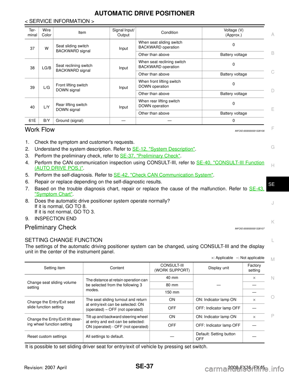
SETTING CHANGE FUNCTION
The settings of the automatic driving positioner system can be changed, using CONSULT-III and the display
unit in the center of the instrument panel.
× : Applicable –: Not applicable
It is possible to set sliding driver seat fo r entry/exit of vehicle by pressing set switch.
37 WSeat sliding switch
BACKWARD signal
InputWhen seat sliding switch
BACKWARD operation
0
Other than above Battery voltage
38 LG/B Seat reclining switch
BACKWARD signal InputWhen seat reclining switch
BACKWARD operation
0
Other than above Battery voltage
39 L/G Front lifting switch
DOWN signal InputWhen front lifting switch
DOWN operation
0
Other than above Battery voltage
40 L/Y Rear lifting switch
DOWN signal
InputWhen rear lifting switch
DOWN operation
0
Other than above Battery voltage
61E B/Y Ground (signal) — — 0 Te r -
minal Wire
Color ItemSignal Input/
Output Condition Voltage (V)
(Approx.)
Setting item Content CONSULT-III
(WORK SUPPORT) Display unitFactory
setting
Change seat sliding volume
setting The distance at retain operation can
be selected from the following 3
modes. 40 mm
—×
80 mm —
150 mm —
Change the Entry/Exit seat
slide function setting The seat sliding turnout and return
at entry/exit can be selected: ON
(operated) – OFF (not operated) ON ON: Indicator lamp ON
×
OFF OFF: Indicator lamp OFF —
Change the Entry/Exit tilt steer-
ing wheel function setting Tilt up and backward steering wheel
at entry and exit can be selected:
ON (operated) - OFF (not operated) ON ON: Indicator lamp ON
×
OFF OFF: Indicator lamp OFF —
Reset custom settings All settings to default. — Default: Setting button
OFF
—
3AA93ABC3ACD3AC03ACA3AC03AC63AC53A913A773A893A873A873A8E3A773A983AC73AC93AC03AC3
3A893A873A873A8F3A773A9D3AAF3A8A3A8C3A863A9D3AAF3A8B3A8C
Page 3679 of 3924
SE-40
< SERVICE INFORMATION >
AUTOMATIC DRIVE POSITIONER
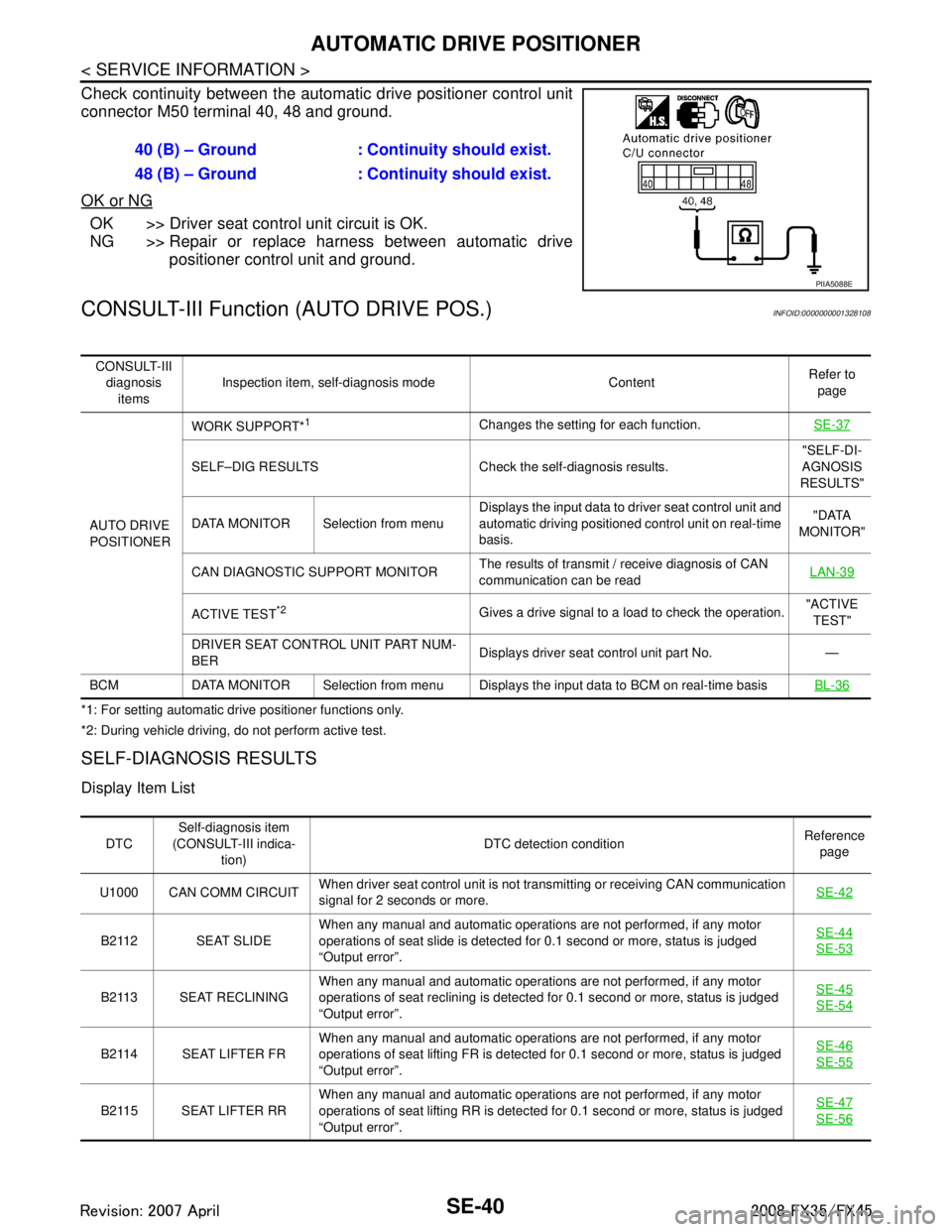
Check continuity between the automatic drive positioner control unit
connector M50 terminal 40, 48 and ground.
OK or NG
OK >> Driver seat control unit circuit is OK.
NG >> Repair or replace harness between automatic drive
positioner control unit and ground.
CONSULT-III Function (AUTO DRIVE POS.)INFOID:0000000001328108
*1: For setting automatic drive positioner functions only.
*2: During vehicle driving, do not perform active test.
SELF-DIAGNOSIS RESULTS
Display Item List
40 (B) – Ground : Continuity should exist.
48 (B) – Ground : Continuity should exist.
PIIA5088E
CONSULT-III
diagnosis items Inspection item, self-diagnosis mode Content
Refer to
page
AUTO DRIVE
POSITIONER WORK SUPPORT*
1Changes the setting for each function.
SE-37
SELF–DIG RESULTS Check the self-diagnosis results. "SELF-DI-
AGNOSIS
RESULTS"
DATA MONITOR Selection from menu Displays the input data to driver seat control unit and
automatic driving positioned control unit on real-time
basis. "DATA
MONITOR"
CAN DIAGNOSTIC SUPPORT MONITOR The results of transmit / receive diagnosis of CAN
communication can be read LAN-39
ACTIVE TEST*2Gives a drive signal to a load to check the operation.
"ACTIVE
TEST"
DRIVER SEAT CONTROL UNIT PART NUM-
BER Displays driver seat control unit part No. —
BCM DATA MONITOR Selection from menu Displays the input data to BCM on real-time basisBL-36
DTCSelf-diagnosis item
(CONSULT-III indica- tion) DTC detection condition
Reference
page
U1000 CAN COMM CIRCUIT When driver seat control unit is not transmitting or receiving CAN communication
signal for 2 seconds or more.
SE-42
B2112 SEAT SLIDEWhen any manual and automatic operations are not performed, if any motor
operations of seat slide is detected for 0.1 second or more, status is judged
“Output error”. SE-44SE-53
B2113 SEAT RECLINING
When any manual and automatic operations are not performed, if any motor
operations of seat reclining is detected for 0.1 second or more, status is judged
“Output error”. SE-45SE-54
B2114 SEAT LIFTER FR
When any manual and automatic operations are not performed, if any motor
operations of seat lifting FR is detected for 0.1 second or more, status is judged
“Output error”. SE-46SE-55
B2115 SEAT LIFTER RR
When any manual and automatic operations are not performed, if any motor
operations of seat lifting RR is detected for 0.1 second or more, status is judged
“Output error”. SE-47SE-56
3AA93ABC3ACD3AC03ACA3AC03AC63AC53A913A773A893A873A873A8E3A773A983AC73AC93AC03AC3
3A893A873A873A8F3A773A9D3AAF3A8A3A8C3A863A9D3AAF3A8B3A8C
Page 3680 of 3924
AUTOMATIC DRIVE POSITIONERSE-41
< SERVICE INFORMATION >
C
DE
F
G H
J
K L
M A
B
SE
N
O P
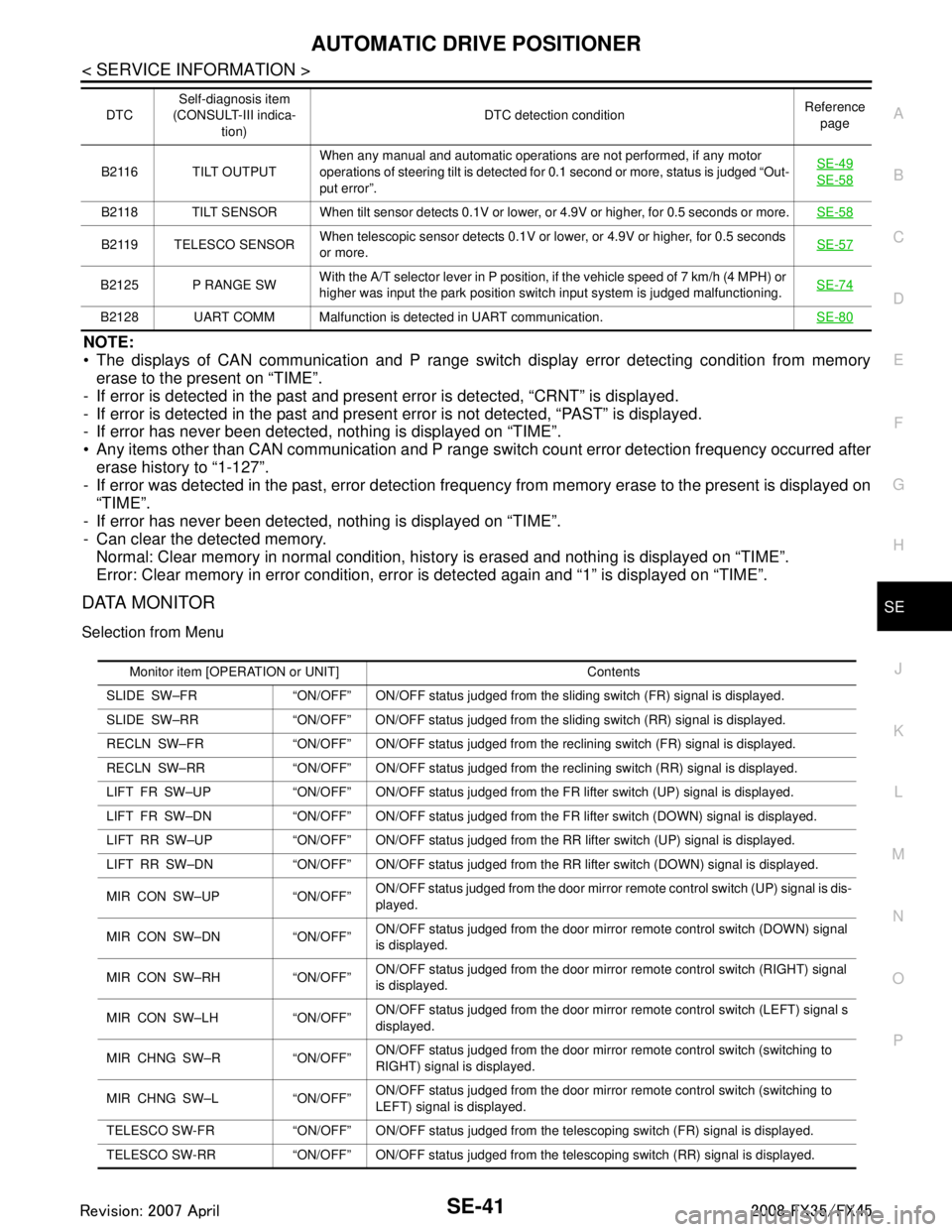
NOTE:
The displays of CAN communication and P range switch display error detecting condition from memory erase to the present on “TIME”.
- If error is detected in the past and present error is detected, “CRNT” is displayed.
- If error is detected in the past and present error is not detected, “PAST” is displayed.
- If error has never been detected, nothing is displayed on “TIME”.
Any items other than CAN communication and P range s witch count error detection frequency occurred after
erase history to “1-127”.
- If error was detected in the past, error detection frequen cy from memory erase to the present is displayed on
“TIME”.
- If error has never been detected, nothing is displayed on “TIME”.
- Can clear the detected memory. Normal: Clear memory in normal condition, hist ory is erased and nothing is displayed on “TIME”.
Error: Clear memory in error condition, error is detected again and “1” is displayed on “TIME”.
DATA MONITOR
Selection from Menu
B2116 TILT OUTPUT When any manual and automatic operations are not performed, if any motor
operations of steering tilt is detected for 0.1 second or more, status is judged “Out-
put error”. SE-49SE-58
B2118 TILT SENSOR When tilt sensor detects 0.1V or lo
wer, or 4.9V or higher, for 0.5 seconds or more.SE-58
B2119 TELESCO SENSORWhen telescopic sensor detects 0.1V or lower, or 4.9V or higher, for 0.5 seconds
or more.
SE-57
B2125 P RANGE SWWith the A/T selector lever in P position, if the vehicle speed of 7 km/h (4 MPH) or
higher was input the park position switch input system is judged malfunctioning. SE-74
B2128 UART COMM Malfunction is detected in UART communication.
SE-80
DTCSelf-diagnosis item
(CONSULT-III indica-
tion) DTC detection condition
Reference
page
Monitor item [OPERATION or UNIT] Contents
SLIDE SW–FR “ON/OFF” ON/OFF status judged from the sliding switch (FR) signal is displayed.
SLIDE SW–RR “ON/OFF” ON/OFF status judged from th e sliding switch (RR) signal is displayed.
RECLN SW–FR “ON/OFF” ON/OFF status judged from the reclining switch (FR) signal is displayed.
RECLN SW–RR “ON/OFF” ON/OFF status judged from the reclining switch (RR) signal is displayed.
LIFT FR SW–UP “ON/OFF” ON/OFF status judged from the FR lifter switch (UP) signal is displayed.
LIFT FR SW–DN “ON/OFF” ON/OFF status judged from the FR lifter switch (DOWN) signal is displayed.
LIFT RR SW–UP “ON/OFF” ON/OFF status judged from the RR lifter switch (UP) signal is displayed.
LIFT RR SW–DN “ON/OFF” ON/OFF status judged from the RR lifter switch (DOWN) signal is displayed.
MIR CON SW–UP “ON/OFF” ON/OFF status judged from the door mirror remote control switch (UP) signal is dis-
played.
MIR CON SW–DN “ON/OFF” ON/OFF status judged from the door mirror remote control switch (DOWN) signal
is displayed.
MIR CON SW–RH “ON/OFF” ON/OFF status judged from the door mirror remote control switch (RIGHT) signal
is displayed.
MIR CON SW–LH “ON/OFF” ON/OFF status judged from the door mirror remote control switch (LEFT) signal s
displayed.
MIR CHNG SW–R “ON/OFF” ON/OFF status judged from the door mirror remote control switch (switching to
RIGHT) signal is displayed.
MIR CHNG SW–L “ON/OFF” ON/OFF status judged from the door mirror remote control switch (switching to
LEFT) signal is displayed.
TELESCO SW-FR “ON/OFF” ON/OFF status judged from the telescoping switch (FR) signal is displayed.
TELESCO SW-RR “ON/OFF” ON/OFF status judged from the telescoping switch (RR) signal is displayed.
3AA93ABC3ACD3AC03ACA3AC03AC63AC53A913A773A893A873A873A8E3A773A983AC73AC93AC03AC3
3A893A873A873A8F3A773A9D3AAF3A8A3A8C3A863A9D3AAF3A8B3A8C
Page 3681 of 3924

SE-42
< SERVICE INFORMATION >
AUTOMATIC DRIVE POSITIONER
ACTIVE TEST
CAUTION:
During vehicle driving, do not perform active test.
NOTE:
If active test is performed, reset seat memory and key fob interlock drive positioner after performing work.
Display Item List
Check CAN Communication SystemINFOID:0000000001532368
1.PERFORM SELF DIAGNOSTIC
1. Turn ignition switch ON and wait for 2 seconds or more.
2. Check “Self Diagnostic Result” of BCM.
TILT SW-UP “ON/OFF” ON/OFF status judged from the tilt switch (UP) signal is displayed.
TILT SW-DOWN “ON/OFF” ON/OFF status judged from the tilt switch (DOWN) signal is displayed.
SET SW “ON/OFF” ON/OFF status judged from the setting switch signal is displayed.
MEMORY SW1 “ON/OFF” ON/OFF status judged from th e seat memory switch 1 signal is displayed.
MEMORY SW2 “ON/OFF” ON/OFF status judged from th e seat memory switch 2 signal is displayed.
P POSI SW “ON/OFF” The selector lever position “ON (P position) / OFF (other than P position)” judged
from the park position switch signal is displayed.
STARTER SW “ON/OFF” Ignition key switch ON (START, ON) /OFF (ignition switch IGN, ACC, or OFF) sta-
tus judged from the ignition switch signal is displayed.
SLIDE PULSE — Value (32768) when battery connects is as standard. If it moves backward, the val-
ue increases. If it moves forward, the value decreases.
RECLN RULSE — Value (32768) when battery connects is as standard. If it moves backward, the val-
ue increases. If it moves forward, the value decreases.
LIFT FR PULSE — Value (32768) when battery connects is as standard. If it moves DOWN, the value
increases. If it moves UP, the value decreases.
LIFT RR PULSE — Value (32768) when battery connects is as standard. If it moves DOWN, the value
increases. If it moves UP, the value decreases.
TILT SEN “V” The tilt position (voltage) judged from the tilt sensor signal is displayed.
TELESCO SEN “V” The telescoping position (voltage) judged from the telescoping sensor signal is dis-
played.
MIR/SE RH R–L “V” Voltage output from RH do or mirror sensor (LH/RH) is displayed.
MIR/SE RH U–D “V” Voltage output from RH door mirror sensor (UP/DOWN) is displayed.
MIR/SE LH R–L “V” Voltage output from LH door mirror sensor (LH/RH) is displayed.
MIR/SE LH U–D “V” Voltage output from LH door mirror sensor (UP/DOWN) is displayed. Monitor item [OPERAT
ION or UNIT] Contents
Test item Description
TILT MOTOR The tilt motor is activated by receiving the drive signal.
TELESCO MOTOR The telescopic motor is activated by receiving the drive signal.
SEAT SLIDE The sliding motor is activated by receiving the drive signal.
SEAT RECLINING The reclining motor is activated by receiving the drive signal.
SEAT LIFTER FR The front end lifter motor is activated by receiving the drive signal.
SEAT LIFTER RR The rear end lifter motor is activated by receiving the drive signal.
MEMORY SW INDCTR The memory sw itch indicator is lit by receivin g the drive signal.
MIRROR MOTOR RH The RH mirror motor moves the mirror UP/DOW
N and LEFT/RIGHT by receiving the drive
signal.
MIRROR MOTOR LH The LH mirror motor moves the mirror UP/DOW
N and LEFT/RIGHT by receiving the drive
signal.
3AA93ABC3ACD3AC03ACA3AC03AC63AC53A913A773A893A873A873A8E3A773A983AC73AC93AC03AC3
3A893A873A873A8F3A773A9D3AAF3A8A3A8C3A863A9D3AAF3A8B3A8C