Page 3461 of 3924
PS-6
< SERVICE INFORMATION >
NOISE, VIBRATION AND HARSHNESS (NVH) TROUBLESHOOTING
NOISE, VIBRATION AND HARSHNESS (NVH) TROUBLESHOOTING
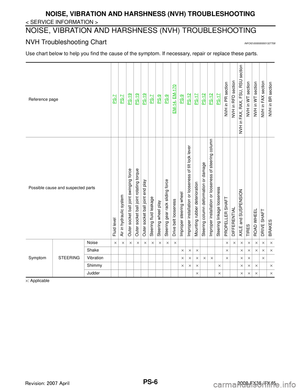
NVH Troubleshooting ChartINFOID:0000000001327708
Use chart below to help you find the cause of the symp tom. If necessary, repair or replace these parts.
×: ApplicableReference page
PS-7PS-7PS-19PS-19PS-19PS-7PS-9PS-9
EM-14
,
EM-170PS-9PS-12PS-17PS-12PS-12PS-17
NVH in PR section
NVH in RFD section
NVH in FAX, RAX, FSU, RSU section NVH in WT section
NVH in WT section
NVH in FAX section
NVH in BR section
Possible cause and suspected parts
Fluid level
Air in hydraulic system
Outer socket ball joint swinging force
Outer socket ball joint rotating torque
Outer socket ball joint end play
Steering fluid leakage
Steering wheel play
Steering gear rack sliding force
Drive belt looseness
Improper steering wheel
Improper installation or looseness of tilt lock lever
Mounting rubber deterioration
Steering column deformation or damage
Improper installation or looseness of steering column
Steering linkage looseness
PROPELLER SHAFT
DIFFERENTIAL
AXLE and SUSPENSION
TIRES
ROAD WHEEL
DRIVE SHAFT
BRAKES
Symptom STEERING Noise
× × ××××× × × ×××××× ×
Shake ××× × ×××× ×
Vibration ××××× × ×× ×
Shimmy ××× × ××× ×
Judder ××××××
3AA93ABC3ACD3AC03ACA3AC03AC63AC53A913A773A893A873A873A8E3A773A983AC73AC93AC03AC3
3A893A873A873A8F3A773A9D3AAF3A8A3A8C3A863A9D3AAF3A8B3A8C
Page 3503 of 3924
NOISE, VIBRATION AND HARSHNESS (NVH) TROUBLESHOOTINGRAX-5
< SERVICE INFORMATION >
CEF
G H
I
J
K L
M A
B
RAX
N
O P
NOISE, VIBRATION AND HARSHN ESS (NVH) TROUBLESHOOTING
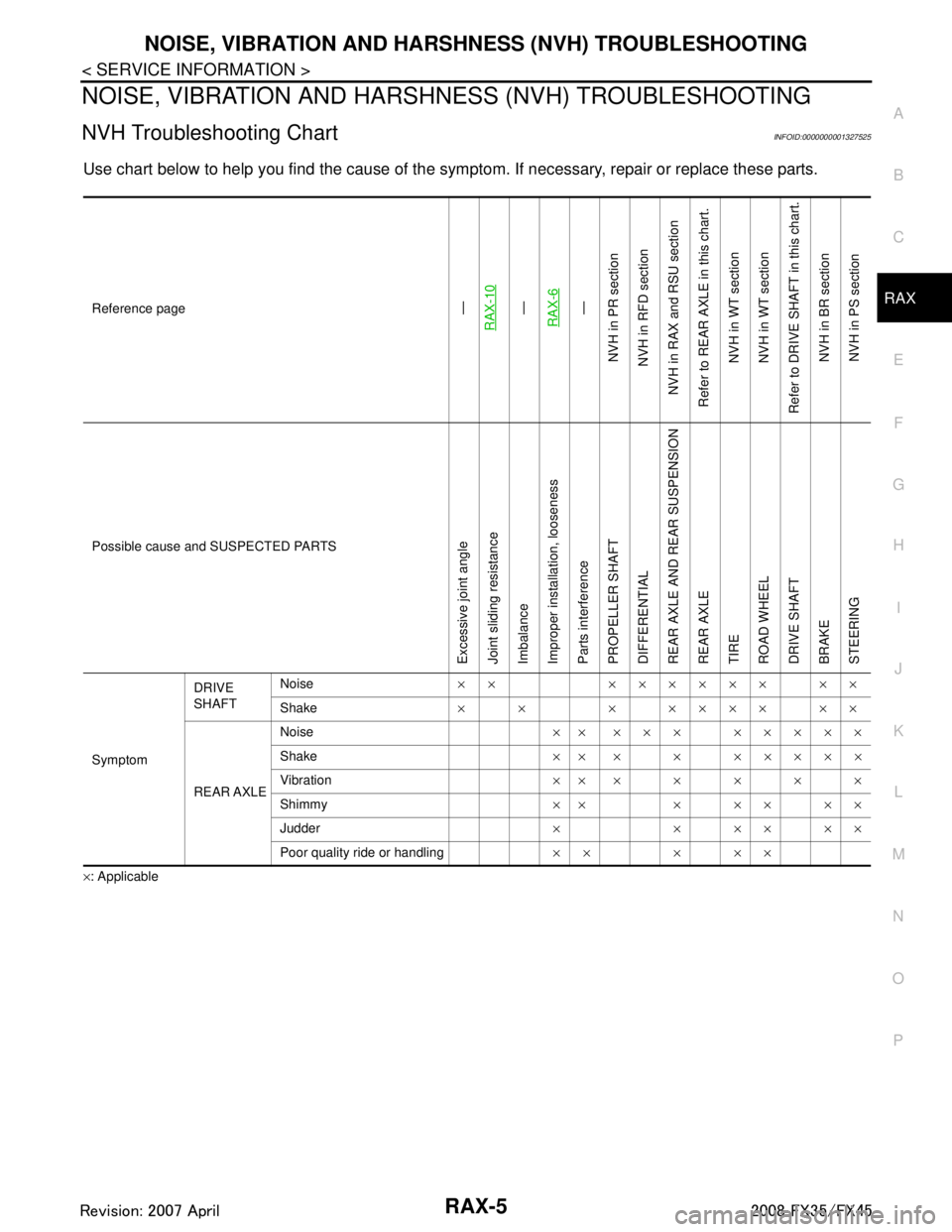
NVH Troubleshooting ChartINFOID:0000000001327525
Use chart below to help you find the cause of the symp tom. If necessary, repair or replace these parts.
×: ApplicableReference page
—
RAX-10—
RAX-6—
NVH in PR section
NVH in RFD section
NVH in RAX and RSU section
Refer to REAR AXLE in this chart. NVH in WT section
NVH in WT section
Refer to DRIVE SHAFT in this chart.
NVH in BR sectionNVH in PS section
Possible cause and SUSPECTED PARTS
Excessive joint angle
Joint sliding resistance
Imbalance
Improper installation, looseness
Parts interference
PROPELLER SHAFT
DIFFERENTIAL
REAR AXLE AND REAR SUSPENSION
REAR AXLE
TIRE
ROAD WHEEL
DRIVE SHAFT
BRAKE
STEERING
Symptom DRIVE
SHAFT
Noise
×× ×××××× ××
Shake × × × ×××× ××
REAR AXLE Noise
×× ××× ×××××
Shake ×× × × ×××××
Vibration ×××××××
Shimmy ×× × × × × ×
Judder × × ×× ××
Poor quality ride or handling ×× × ××
3AA93ABC3ACD3AC03ACA3AC03AC63AC53A913A773A893A873A873A8E3A773A983AC73AC93AC03AC3
3A893A873A873A8F3A773A9D3AAF3A8A3A8C3A863A9D3AAF3A8B3A8C
Page 3543 of 3924
RFD-1
DRIVELINE/AXLE
CEF
G H
I
J
K L
M
SECTION RFD
A
B
RFD
N
O P
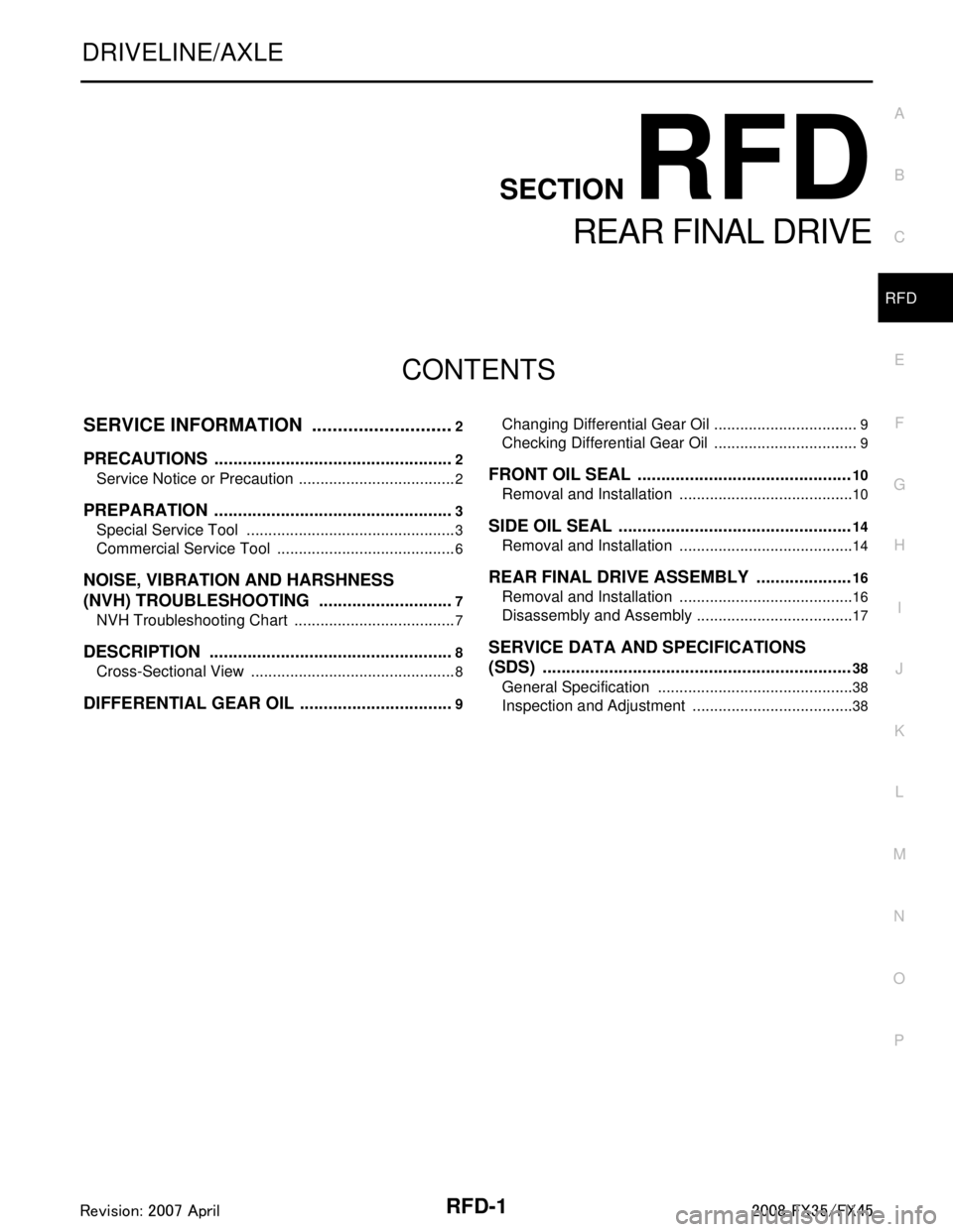
CONTENTS
REAR FINAL DRIVE
SERVICE INFORMATION .. ..........................2
PRECAUTIONS .............................................. .....2
Service Notice or Precaution ............................... ......2
PREPARATION ...................................................3
Special Service Tool ........................................... ......3
Commercial Service Tool ..........................................6
NOISE, VIBRATION AND HARSHNESS
(NVH) TROUBLESHOOTING .............................
7
NVH Troubleshooting Chart ................................ ......7
DESCRIPTION ....................................................8
Cross-Sectional View .......................................... ......8
DIFFERENTIAL GEAR OIL .................................9
Changing Differential Gear Oil ............................. .....9
Checking Differential Gear Oil ..................................9
FRONT OIL SEAL .............................................10
Removal and Installation .........................................10
SIDE OIL SEAL .................................................14
Removal and Installation .........................................14
REAR FINAL DRIVE ASSEMBLY ....................16
Removal and Installation .........................................16
Disassembly and Assembly .....................................17
SERVICE DATA AND SPECIFICATIONS
(SDS) .................................................................
38
General Specification ..............................................38
Inspection and Adjustment ......................................38
3AA93ABC3ACD3AC03ACA3AC03AC63AC53A913A773A893A873A873A8E3A773A983AC73AC93AC03AC3
3A893A873A873A8F3A773A9D3AAF3A8A3A8C3A863A9D3AAF3A8B3A8C
Page 3546 of 3924
RFD-4
< SERVICE INFORMATION >
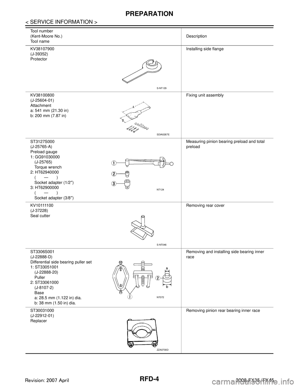
PREPARATION
KV38107900
(J-39352)
ProtectorInstalling side flange
KV38100800
(J-25604-01)
Attachment
a: 541 mm (21.30 in)
b: 200 mm (7.87 in) Fixing unit assembly
ST3127S000
(J-25765-A)
Preload gauge
1: GG91030000 (J-25765)
Torque wrench
2: HT62940000 (—)
Socket adapter (1/2 ″)
3: HT62900000 (—)
Socket adapter (3/8 ″) Measuring pinion bearing preload and total
preload
K V 1 0 1111 0 0
(J-37228)
Seal cutter Removing rear cover
ST3306S001
(J-22888-D)
Differential side bearing puller set
1: ST33051001 (J-22888-20)
Puller
2: ST33061000 (J-8107-2)
Base
a: 28.5 mm (1.122 in) dia.
b: 38 mm (1.50 in) dia. Removing and installing side bearing inner
race
ST30031000
(J-22912-01)
Replacer Removing pinion rear bearing inner race
Tool number
(Kent-Moore No.)
Tool name
Description
S-NT129
SDIA0267E
NT124
S-NT046
NT072
ZZA0700D
3AA93ABC3ACD3AC03ACA3AC03AC63AC53A913A773A893A873A873A8E3A773A983AC73AC93AC03AC3
3A893A873A873A8F3A773A9D3AAF3A8A3A8C3A863A9D3AAF3A8B3A8C
Page 3548 of 3924
RFD-6
< SERVICE INFORMATION >
PREPARATION
Commercial Service Tool
INFOID:0000000001327492
(J-34309)
Differential shim selector tool Adjusting bearing preload and pinion gear
height
(J-25269-4)
Side bearing disc (2 Req'd) Selecting pinion height adjusting washer
Tool number
(Kent-Moore No.)
Tool name
Description
NT134
NT136
Tool name
Description
Flange wrench Removing and installing drive pinion lock nut
Spacer
a: 60 mm (2.36 in) dia.
b: 36 mm (1.42 in) dia.
c: 30 mm (1.18 in) Installing pinion front bearing inner race
Power tool Loosening nuts and bolts
NT035
ZZA1133D
PBIC0190E
3AA93ABC3ACD3AC03ACA3AC03AC63AC53A913A773A893A873A873A8E3A773A983AC73AC93AC03AC3
3A893A873A873A8F3A773A9D3AAF3A8A3A8C3A863A9D3AAF3A8B3A8C
Page 3549 of 3924
NOISE, VIBRATION AND HARSHNESS (NVH) TROUBLESHOOTINGRFD-7
< SERVICE INFORMATION >
CEF
G H
I
J
K L
M A
B
RFD
N
O P
NOISE, VIBRATION AND HARSHN ESS (NVH) TROUBLESHOOTING
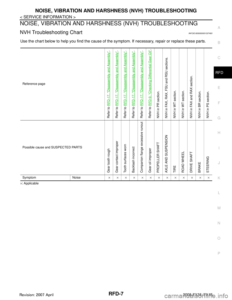
NVH Troubleshooting ChartINFOID:0000000001327493
Use the chart below to help you find t he cause of the symptom. If necessary, repair or replace these parts.
×: ApplicableReference page
Refer to
RFD-17, "
Disassembly and Assembly
".
Refer to RFD-17, "
Disassembly and Assembly
".
Refer to RFD-17, "
Disassembly and Assembly
".
Refer to RFD-17, "
Disassembly and Assembly
".
Refer to RFD-17, "
Disassembly and Assembly
".
Refer to RFD-9, "
Checking Differential Gear Oil
".
NVH in PR section.
NVH in FAX, RAX, FSU and RSU sections.
NVH in WT section.
NVH in WT section.
NVH in FAX and RAX section.
NVH in BR section.
NVH in PS section.
Possible cause and SUSPECTED PARTS
Gear tooth rough
Gear contact improper
Tooth surfaces worn
Backlash incorrect
Companion flange excessive runout
Gear oil improper
PROPELLER SHAFT
AXLE AND SUSPENSION
TIRE
ROAD WHEEL
DRIVE SHAFT
BRAKE
STEERING
Symptom Noise ×××××××××××××
3AA93ABC3ACD3AC03ACA3AC03AC63AC53A913A773A893A873A873A8E3A773A983AC73AC93AC03AC3
3A893A873A873A8F3A773A9D3AAF3A8A3A8C3A863A9D3AAF3A8B3A8C
Page 3550 of 3924
RFD-8
< SERVICE INFORMATION >
DESCRIPTION
DESCRIPTION
Cross-Sectional ViewINFOID:0000000001327494
1. Side flange 2. Pinion mate gear 3. Drive gear
4. Pinion mate shaft 5. Differential case 6. Side bearing
7. Drive pinion 8. Pinion front bearing 9. Companion flange
10. Collapsible spacer 11. Pinion rear bearing 12. Side gear
PDIA0476E
3AA93ABC3ACD3AC03ACA3AC03AC63AC53A913A773A893A873A873A8E3A773A983AC73AC93AC03AC3
3A893A873A873A8F3A773A9D3AAF3A8A3A8C3A863A9D3AAF3A8B3A8C
Page 3551 of 3924
DIFFERENTIAL GEAR OILRFD-9
< SERVICE INFORMATION >
CEF
G H
I
J
K L
M A
B
RFD
N
O P
DIFFERENTIAL GEAR OIL
Changing Differential Gear OilINFOID:0000000001327495
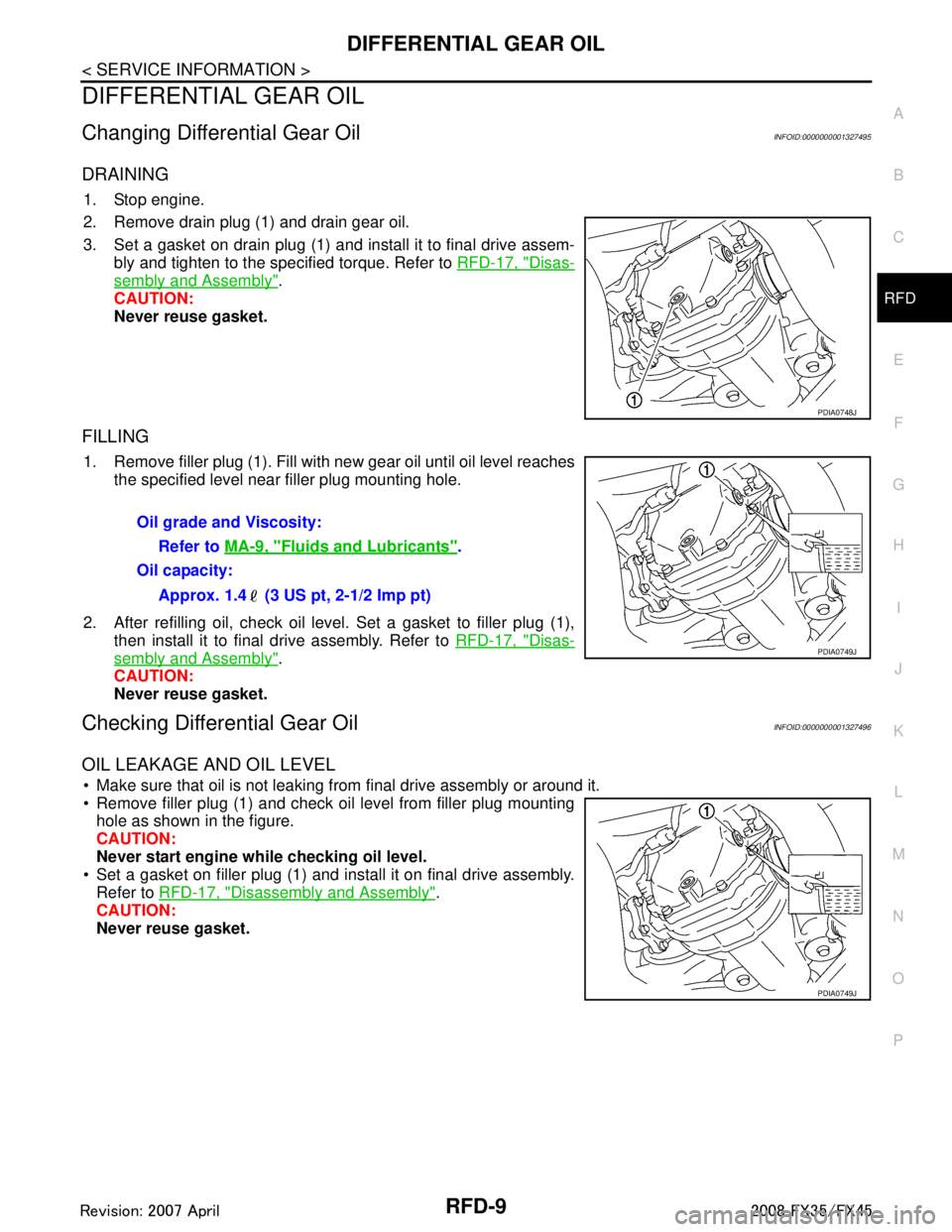
DRAINING
1. Stop engine.
2. Remove drain plug (1) and drain gear oil.
3. Set a gasket on drain plug (1) and install it to final drive assem- bly and tighten to the specified torque. Refer to RFD-17, "
Disas-
sembly and Assembly".
CAUTION:
Never reuse gasket.
FILLING
1. Remove filler plug (1). Fill with new gear oil until oil level reaches the specified level near filler plug mounting hole.
2. After refilling oil, check oil level. Set a gasket to filler plug (1), then install it to final drive assembly. Refer to RFD-17, "
Disas-
sembly and Assembly".
CAUTION:
Never reuse gasket.
Checking Differential Gear OilINFOID:0000000001327496
OIL LEAKAGE AND OIL LEVEL
Make sure that oil is not leaking from final drive assembly or around it.
Remove filler plug (1) and check oil level from filler plug mounting hole as shown in the figure.
CAUTION:
Never start engine while checking oil level.
Set a gasket on filler plug (1) and install it on final drive assembly.
Refer to RFD-17, "
Disassembly and Assembly".
CAUTION:
Never reuse gasket.
PDIA0748J
Oil grade and Viscosity:
Refer to MA-9, "
Fluids and Lubricants".
Oil capacity:
Approx. 1.4 (3 US pt, 2-1/2 Imp pt)
PDIA0749J
PDIA0749J
3AA93ABC3ACD3AC03ACA3AC03AC63AC53A913A773A893A873A873A8E3A773A983AC73AC93AC03AC3
3A893A873A873A8F3A773A9D3AAF3A8A3A8C3A863A9D3AAF3A8B3A8C