Page 2797 of 3924
FFD-6
< SERVICE INFORMATION >
NOISE, VIBRATION AND HARSHNESS (NVH) TROUBLESHOOTING
NOISE, VIBRATION AND HARSHNESS (NVH) TROUBLESHOOTING
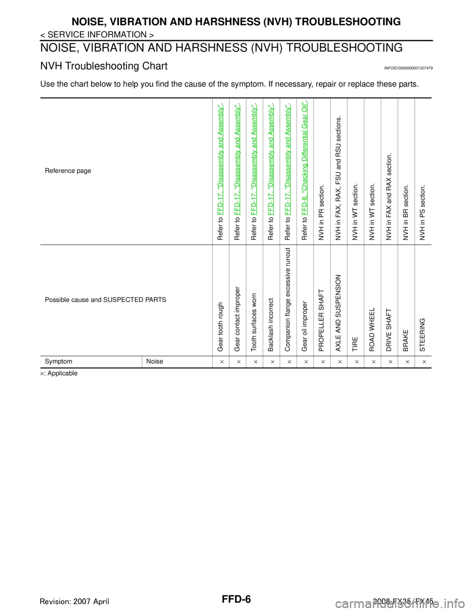
NVH Troubleshooting ChartINFOID:0000000001327479
Use the chart below to help you find the cause of the sy mptom. If necessary, repair or replace these parts.
×: ApplicableReference page
Refer to
FFD-17, "
Disassembly and Assembly
".
Refer to FFD-17, "
Disassembly and Assembly
".
Refer to FFD-17, "
Disassembly and Assembly
".
Refer to FFD-17, "
Disassembly and Assembly
".
Refer to FFD-17, "
Disassembly and Assembly
".
Refer to FFD-8, "
Checking Differential Gear Oil
".
NVH in PR section.
NVH in FAX, RAX, FSU and RSU sections.
NVH in WT section.
NVH in WT section.
NVH in FAX and RAX section.
NVH in BR section.
NVH in PS section.
Possible cause and SUSPECTED PARTS
Gear tooth rough
Gear contact improper
Tooth surfaces worn
Backlash incorrect
Companion flange excessive runout
Gear oil improper
PROPELLER SHAFT
AXLE AND SUSPENSION
TIRE
ROAD WHEEL
DRIVE SHAFT
BRAKE
STEERING
Symptom Noise ×××××××××××××
3AA93ABC3ACD3AC03ACA3AC03AC63AC53A913A773A893A873A873A8E3A773A983AC73AC93AC03AC3
3A893A873A873A8F3A773A9D3AAF3A8A3A8C3A863A9D3AAF3A8B3A8C
Page 2798 of 3924
DESCRIPTIONFFD-7
< SERVICE INFORMATION >
CEF
G H
I
J
K L
M A
B
FFD
N
O P
DESCRIPTION
Cross-Sectional ViewINFOID:0000000001327480
VQ35DE models
VK45DE models
PDIA0647E
1. Side retainer 2. Side bearing 3. Differential case
4. Drive gear 5. Pinion mate shaft 6. Pinion mate gear
7. Side gear 8. Side shaft 9. Gear carrier
10. Drive pinion 11. Companion flange 12. Pinion front bearing
13. Pinion rear bearing 14. Extension tube retainer 15. Engine assembly
PDIA1214E
1. Side retainer 2. Side bearing 3. Differential case
4. Drive gear 5. Pinion mate shaft 6. Pinion mate gear
7. Side gear 8. Side shaft 9. Gear carrier
10. Drive pinion 11. Companion flange 12. Pinion front bearing
13. Pinion rear bearing 14. Extension tube retainer 15. Engine assembly
3AA93ABC3ACD3AC03ACA3AC03AC63AC53A913A773A893A873A873A8E3A773A983AC73AC93AC03AC3
3A893A873A873A8F3A773A9D3AAF3A8A3A8C3A863A9D3AAF3A8B3A8C
Page 2799 of 3924
FFD-8
< SERVICE INFORMATION >
DIFFERENTIAL GEAR OIL
DIFFERENTIAL GEAR OIL
Changing Differential Gear OilINFOID:0000000001327481
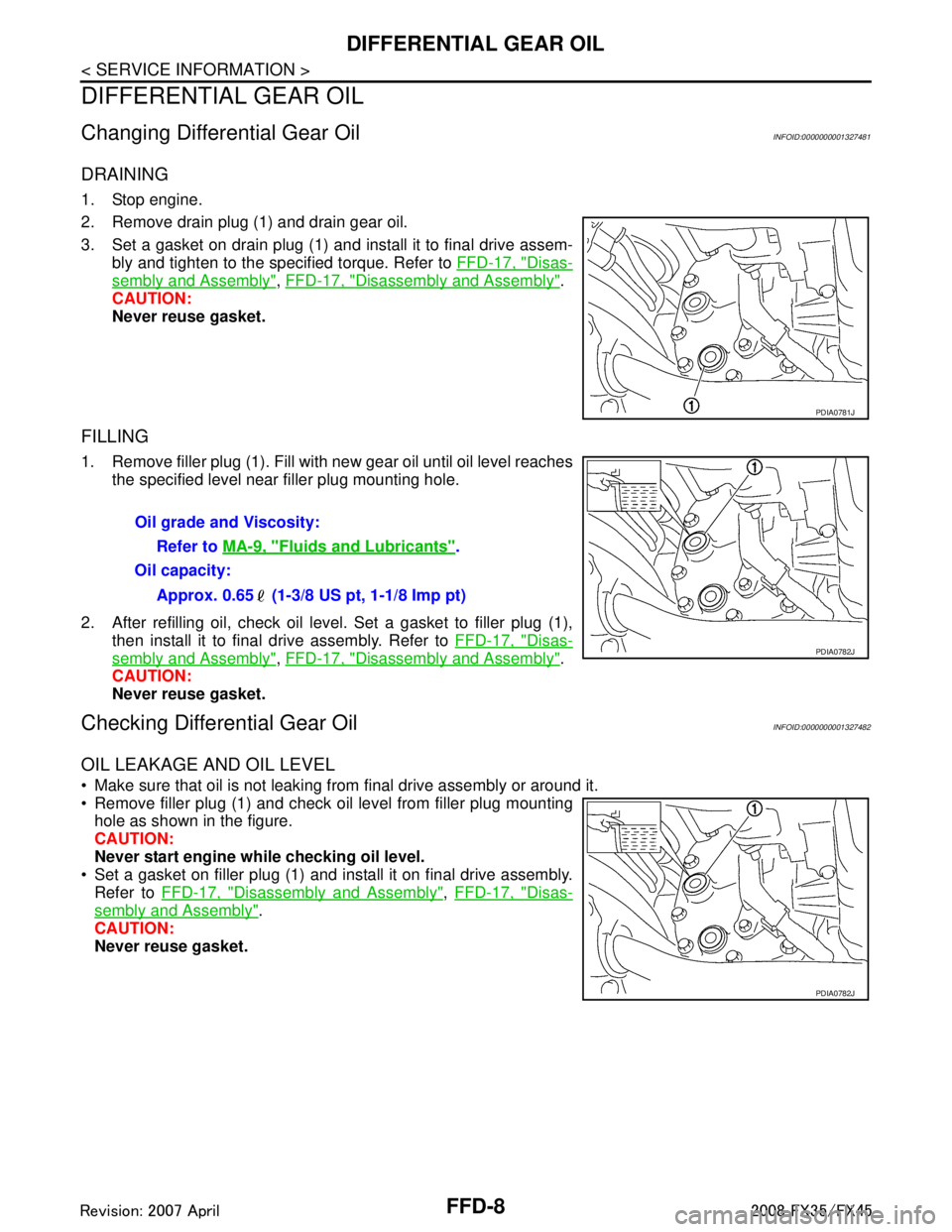
DRAINING
1. Stop engine.
2. Remove drain plug (1) and drain gear oil.
3. Set a gasket on drain plug (1) and install it to final drive assem-bly and tighten to the specified torque. Refer to FFD-17, "
Disas-
sembly and Assembly", FFD-17, "Disassembly and Assembly".
CAUTION:
Never reuse gasket.
FILLING
1. Remove filler plug (1). Fill with new gear oil until oil level reaches the specified level near filler plug mounting hole.
2. After refilling oil, check oil level. Set a gasket to filler plug (1), then install it to final drive assembly. Refer to FFD-17, "
Disas-
sembly and Assembly", FFD-17, "Disassembly and Assembly".
CAUTION:
Never reuse gasket.
Checking Differential Gear OilINFOID:0000000001327482
OIL LEAKAGE AND OIL LEVEL
Make sure that oil is not leaking fr om final drive assembly or around it.
Remove filler plug (1) and check oil level from filler plug mounting hole as shown in the figure.
CAUTION:
Never start engine while checking oil level.
Set a gasket on filler plug (1) and install it on final drive assembly.
Refer to FFD-17, "
Disassembly and Assembly", FFD-17, "Disas-
sembly and Assembly".
CAUTION:
Never reuse gasket.
PDIA0781J
Oil grade and Viscosity:
Refer to MA-9, "
Fluids and Lubricants".
Oil capacity:
Approx. 0.65 (1-3/8 US pt, 1-1/8 Imp pt)
PDIA0782J
PDIA0782J
3AA93ABC3ACD3AC03ACA3AC03AC63AC53A913A773A893A873A873A8E3A773A983AC73AC93AC03AC3
3A893A873A873A8F3A773A9D3AAF3A8A3A8C3A863A9D3AAF3A8B3A8C
Page 2800 of 3924
FRONT OIL SEALFFD-9
< SERVICE INFORMATION >
CEF
G H
I
J
K L
M A
B
FFD
N
O P
FRONT OIL SEAL
Removal and InstallationINFOID:0000000001327483
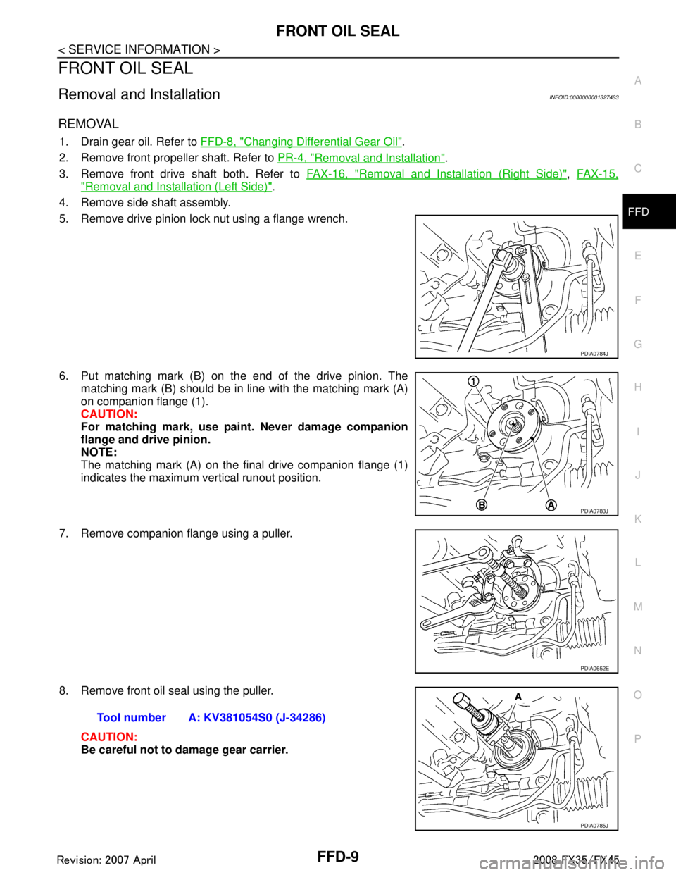
REMOVAL
1. Drain gear oil. Refer to FFD-8, "Changing Differential Gear Oil".
2. Remove front propeller shaft. Refer to PR-4, "
Removal and Installation".
3. Remove front drive shaft both. Refer to FAX-16, "
Removal and Installation (Right Side)", FAX-15,
"Removal and Installation (Left Side)".
4. Remove side shaft assembly.
5. Remove drive pinion lock nut using a flange wrench.
6. Put matching mark (B) on the end of the drive pinion. The matching mark (B) should be in line with the matching mark (A)
on companion flange (1).
CAUTION:
For matching mark, use pain t. Never damage companion
flange and drive pinion.
NOTE:
The matching mark (A) on the final drive companion flange (1)
indicates the maximum vertical runout position.
7. Remove companion flange using a puller.
8. Remove front oil seal using the puller. CAUTION:
Be careful not to damage gear carrier.
PDIA0784J
PDIA0783J
PDIA0652E
Tool number A: KV381054S0 (J-34286)
PDIA0785J
3AA93ABC3ACD3AC03ACA3AC03AC63AC53A913A773A893A873A873A8E3A773A983AC73AC93AC03AC3
3A893A873A873A8F3A773A9D3AAF3A8A3A8C3A863A9D3AAF3A8B3A8C
Page 2802 of 3924
FRONT OIL SEALFFD-11
< SERVICE INFORMATION >
CEF
G H
I
J
K L
M A
B
FFD
N
O P
9. Refill gear oil to the final drive and check oil level. Refer to FFD-8, "Changing Differential Gear Oil".
10. Check the final drive for oil leakage. Refer to FFD-8, "
Checking Differential Gear Oil".
3AA93ABC3ACD3AC03ACA3AC03AC63AC53A913A773A893A873A873A8E3A773A983AC73AC93AC03AC3
3A893A873A873A8F3A773A9D3AAF3A8A3A8C3A863A9D3AAF3A8B3A8C
Page 2804 of 3924
SIDE OIL SEALFFD-13
< SERVICE INFORMATION >
CEF
G H
I
J
K L
M A
B
FFD
N
O P
4. Install the front drive shaft. Refer to FAX-15, "Removal and Installation (Left Side)".
5. When oil leaks while removing, check oil level after the installation. Refer to FFD-8, "
Checking Differential
Gear Oil".
3AA93ABC3ACD3AC03ACA3AC03AC63AC53A913A773A893A873A873A8E3A773A983AC73AC93AC03AC3
3A893A873A873A8F3A773A9D3AAF3A8A3A8C3A863A9D3AAF3A8B3A8C
Page 2806 of 3924
FRONT FINAL DRIVE ASSEMBLYFFD-15
< SERVICE INFORMATION >
CEF
G H
I
J
K L
M A
B
FFD
N
O P
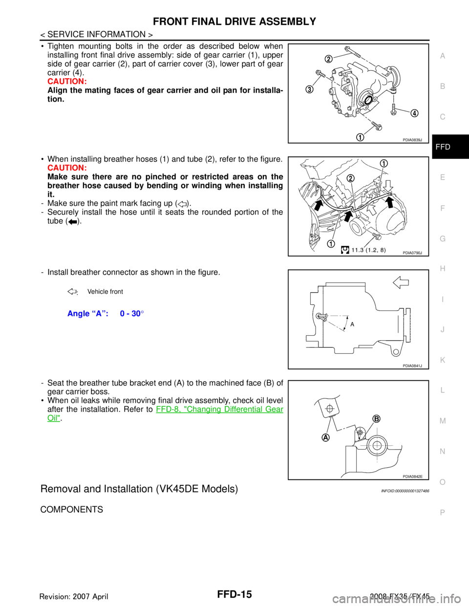
Tighten mounting bolts in the order as described below when installing front final drive assembly: side of gear carrier (1), upper
side of gear carrier (2), part of ca rrier cover (3), lower part of gear
carrier (4).
CAUTION:
Align the mating faces of gear car rier and oil pan for installa-
tion.
When installing breather hoses (1) and tube (2), refer to the figure. CAUTION:
Make sure there are no pinched or restricted areas on the
breather hose caused by bending or winding when installing
it.
- Make sure the paint mark facing up ( ).
- Securely install the hose until it seats the rounded portion of the
tube ( ).
- Install breather connector as shown in the figure.
- Seat the breather tube bracket end (A) to the machined face (B) of gear carrier boss.
When oil leaks while removing final drive assembly, check oil level after the installation. Refer to FFD-8, "
Changing Differential Gear
Oil".
Removal and Installation (VK45DE Models)INFOID:0000000001327486
COMPONENTS
PDIA0839J
PDIA0790J
:Vehicle front
Angle “A”: 0 - 30
°
PDIA0841J
PDIA0842E
3AA93ABC3ACD3AC03ACA3AC03AC63AC53A913A773A893A873A873A8E3A773A983AC73AC93AC03AC3
3A893A873A873A8F3A773A9D3AAF3A8A3A8C3A863A9D3AAF3A8B3A8C
Page 2808 of 3924
FRONT FINAL DRIVE ASSEMBLYFFD-17
< SERVICE INFORMATION >
CEF
G H
I
J
K L
M A
B
FFD
N
O P
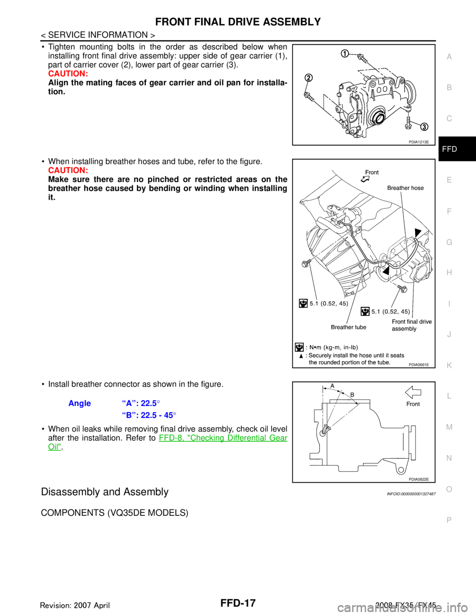
Tighten mounting bolts in the order as described below when installing front final drive assembly: upper side of gear carrier (1),
part of carrier cover (2), lower part of gear carrier (3).
CAUTION:
Align the mating faces of gear car rier and oil pan for installa-
tion.
When installing breather hoses and tube, refer to the figure. CAUTION:
Make sure there are no pinched or restricted areas on the
breather hose caused by bending or winding when installing
it.
Install breather connector as shown in the figure.
When oil leaks while removing final drive assembly, check oil level after the installation. Refer to FFD-8, "
Checking Differential Gear
Oil".
Disassembly and AssemblyINFOID:0000000001327487
COMPONENTS (VQ35DE MODELS)
PDIA1213E
PDIA0661E
Angle “A”: 22.5°
“B”: 22.5 - 45 °
PDIA0822E
3AA93ABC3ACD3AC03ACA3AC03AC63AC53A913A773A893A873A873A8E3A773A983AC73AC93AC03AC3
3A893A873A873A8F3A773A9D3AAF3A8A3A8C3A863A9D3AAF3A8B3A8C