Page 3266 of 3924

LT-164
< SERVICE INFORMATION >
INTERIOR ROOM LAMP
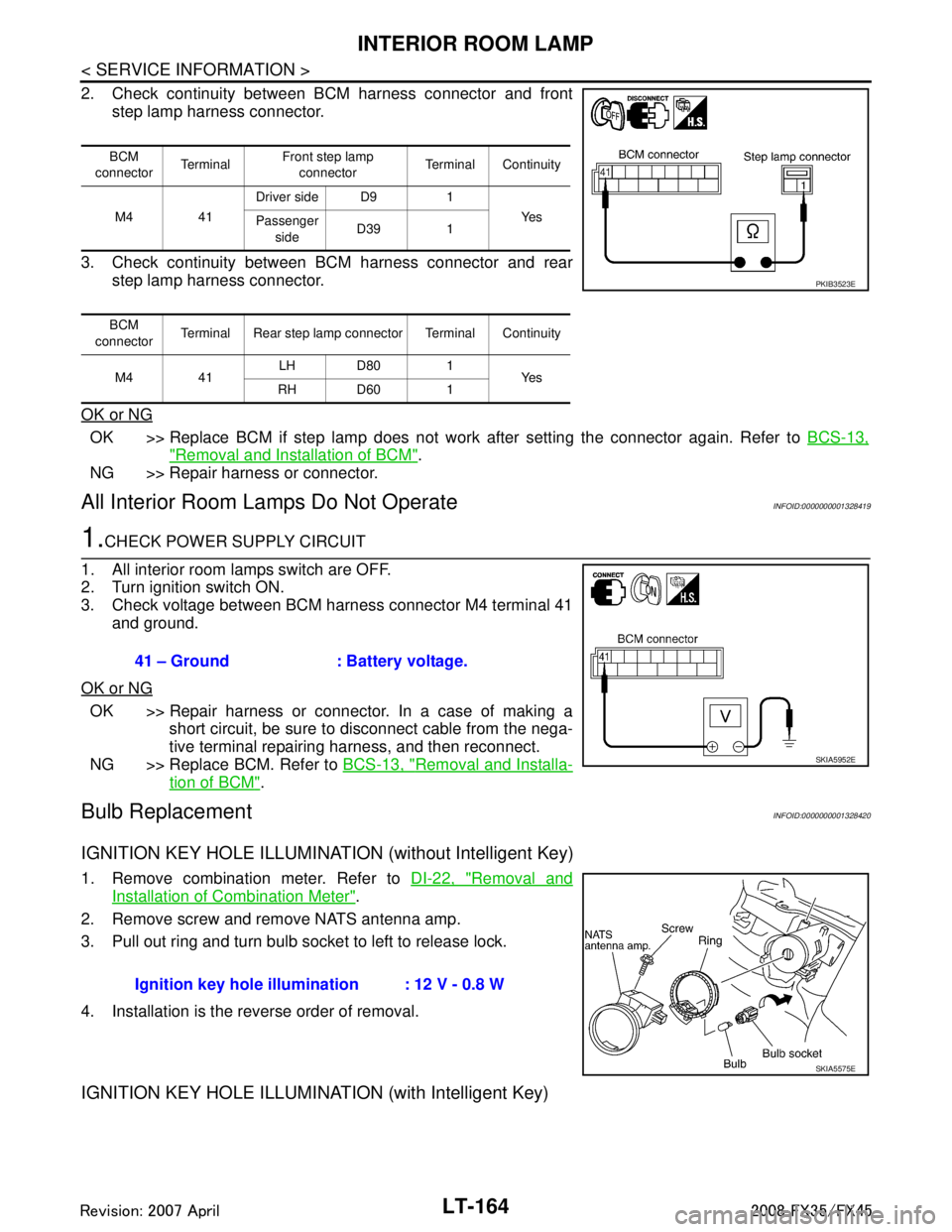
2. Check continuity between BCM harness connector and frontstep lamp harness connector.
3. Check continuity between BCM harness connector and rear step lamp harness connector.
OK or NG
OK >> Replace BCM if step lamp does not work after setting the connector again. Refer to BCS-13,
"Removal and Installation of BCM".
NG >> Repair harness or connector.
All Interior Room La mps Do Not OperateINFOID:0000000001328419
1.CHECK POWER SUPPLY CIRCUIT
1. All interior room lamps switch are OFF.
2. Turn ignition switch ON.
3. Check voltage between BCM harness connector M4 terminal 41 and ground.
OK or NG
OK >> Repair harness or connector. In a case of making a short circuit, be sure to disconnect cable from the nega-
tive terminal repairing harness, and then reconnect.
NG >> Replace BCM. Refer to BCS-13, "
Removal and Installa-
tion of BCM".
Bulb ReplacementINFOID:0000000001328420
IGNITION KEY HOLE ILLUMINATION (without Intelligent Key)
1. Remove combination meter. Refer to DI-22, "Removal and
Installation of Combination Meter".
2. Remove screw and remove NATS antenna amp.
3. Pull out ring and turn bulb socket to left to release lock.
4. Installation is the reverse order of removal.
IGNITION KEY HOLE ILLUMINA TION (with Intelligent Key)
BCM
connector Te r m i n a l Front step lamp
connector Terminal Continuity
M4 41 Driver side D9 1
Ye s
Passenger
side D39 1
BCM
connector Terminal Rear step lamp connector Terminal Continuity
M4 41 LH D80 1
Ye s
RH D60 1
PKIB3523E
41 – Ground : Battery voltage.
SKIA5952E
Ignition key hole illu mination : 12 V - 0.8 W
SKIA5575E
3AA93ABC3ACD3AC03ACA3AC03AC63AC53A913A773A893A873A873A8E3A773A983AC73AC93AC03AC3
3A893A873A873A8F3A773A9D3AAF3A8A3A8C3A863A9D3AAF3A8B3A8C
Page 3267 of 3924

INTERIOR ROOM LAMPLT-165
< SERVICE INFORMATION >
C
DE
F
G H
I
J
L
M A
B
LT
N
O P
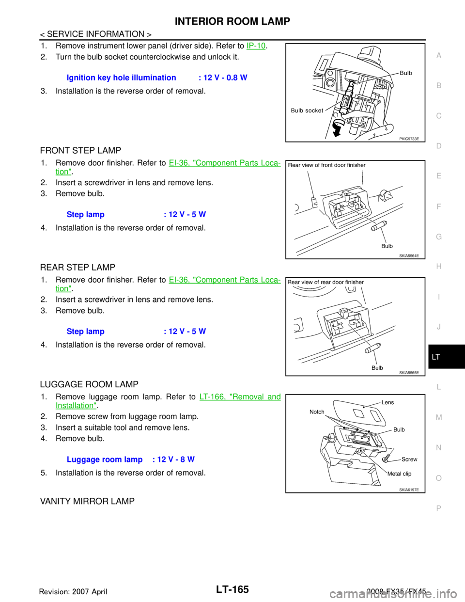
1. Remove instrument lower panel (driver side). Refer to IP-10.
2. Turn the bulb socket counterclockwise and unlock it.
3. Installation is the reverse order of removal.
FRONT STEP LAMP
1. Remove door finisher. Refer to EI-36, "Component Parts Loca-
tion".
2. Insert a screwdriver in lens and remove lens.
3. Remove bulb.
4. Installation is the reverse order of removal.
REAR STEP LAMP
1. Remove door finisher. Refer to EI-36, "Component Parts Loca-
tion".
2. Insert a screwdriver in lens and remove lens.
3. Remove bulb.
4. Installation is the reverse order of removal.
LUGGAGE ROOM LAMP
1. Remove luggage room lamp. Refer to LT-166, "Removal and
Installation".
2. Remove screw from luggage room lamp.
3. Insert a suitable tool and remove lens.
4. Remove bulb.
5. Installation is the reverse order of removal.
VANITY MIRROR LAMP
Ignition key hole illumination : 12 V - 0.8 W
PKIC9733E
Step lamp : 12 V - 5 W
SKIA5564E
Step lamp : 12 V - 5 W
SKIA5565E
Luggage room lamp : 12 V - 8 W
SKIA6197E
3AA93ABC3ACD3AC03ACA3AC03AC63AC53A913A773A893A873A873A8E3A773A983AC73AC93AC03AC3
3A893A873A873A8F3A773A9D3AAF3A8A3A8C3A863A9D3AAF3A8B3A8C
Page 3268 of 3924

LT-166
< SERVICE INFORMATION >
INTERIOR ROOM LAMP
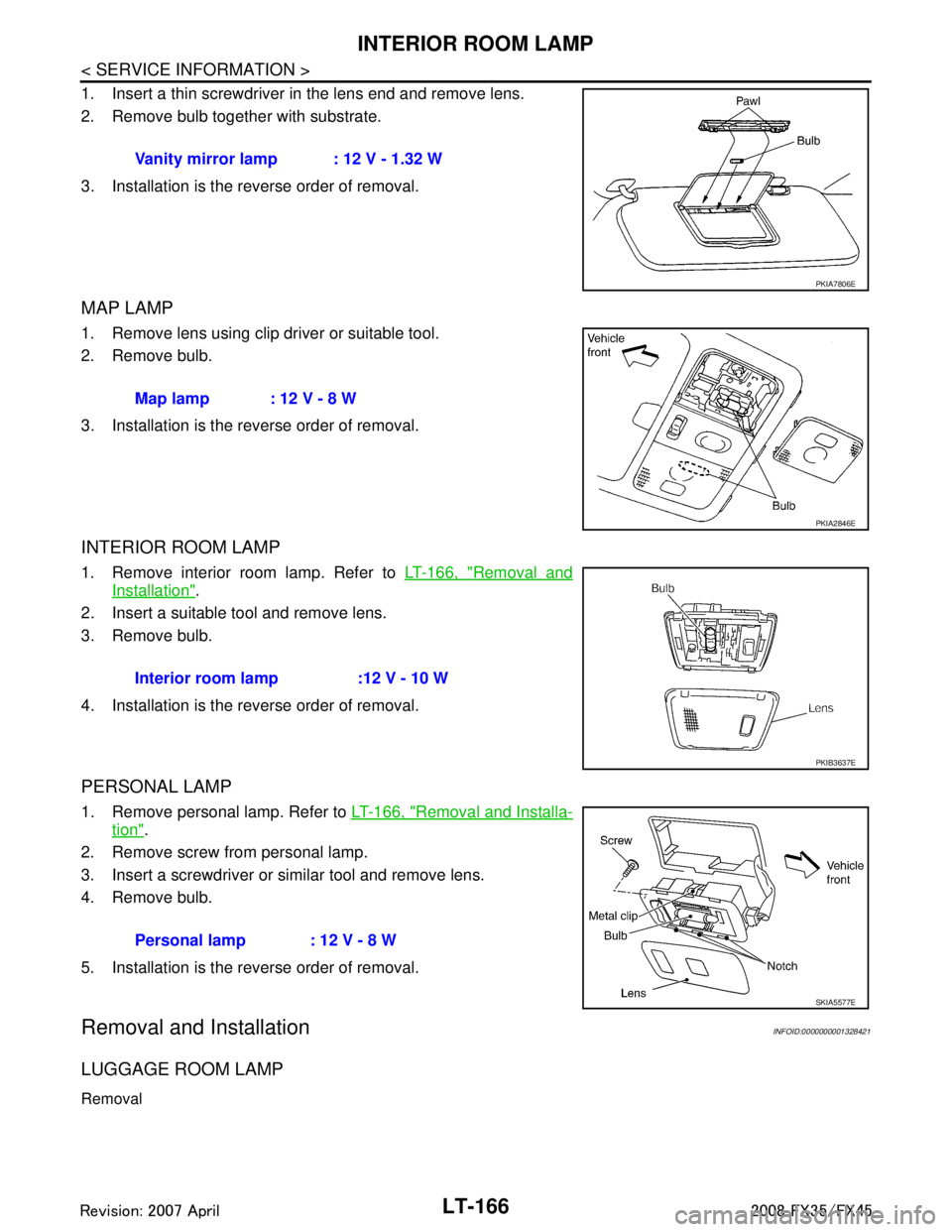
1. Insert a thin screwdriver in the lens end and remove lens.
2. Remove bulb together with substrate.
3. Installation is the reverse order of removal.
MAP LAMP
1. Remove lens using clip driver or suitable tool.
2. Remove bulb.
3. Installation is the reverse order of removal.
INTERIOR ROOM LAMP
1. Remove interior room lamp. Refer to LT-166, "Removal and
Installation".
2. Insert a suitable tool and remove lens.
3. Remove bulb.
4. Installation is the reverse order of removal.
PERSONAL LAMP
1. Remove personal lamp. Refer to LT-166, "Removal and Installa-
tion".
2. Remove screw from personal lamp.
3. Insert a screwdriver or similar tool and remove lens.
4. Remove bulb.
5. Installation is the reverse order of removal.
Removal and InstallationINFOID:0000000001328421
LUGGAGE ROOM LAMP
Removal
Vanity mirror lamp : 12 V - 1.32 W
PKIA7806E
Map lamp : 12 V - 8 W
PKIA2846E
Interior room lamp :12 V - 10 W
PKIB3637E
Personal lamp : 12 V - 8 W
SKIA5577E
3AA93ABC3ACD3AC03ACA3AC03AC63AC53A913A773A893A873A873A8E3A773A983AC73AC93AC03AC3
3A893A873A873A8F3A773A9D3AAF3A8A3A8C3A863A9D3AAF3A8B3A8C
Page 3283 of 3924
ILLUMINATIONLT-181
< SERVICE INFORMATION >
C
DE
F
G H
I
J
L
M A
B
LT
N
O P
Bulb ReplacementINFOID:0000000001328427
GLOVE BOX LAMP
1. Remove instrument passenger lower panel. Refer to IP-16, "Disassembly and Assembly".
TKWM4337E
3AA93ABC3ACD3AC03ACA3AC03AC63AC53A913A773A893A873A873A8E3A773A983AC73AC93AC03AC3
3A893A873A873A8F3A773A9D3AAF3A8A3A8C3A863A9D3AAF3A8B3A8C
Page 3284 of 3924
LT-182
< SERVICE INFORMATION >
ILLUMINATION
2. Turn bulb socket left to release lock and remove it.
3. Installation is the reverse order of removal.
A/T DEVICE ILLUMINATION
1. Remove A/T console finisher. Refer to IP-10.
2. Turn bulb socket left to release lock and remove it.
3. Installation is the reverse order of removal.
COIN BOX ILLUMINATION
1. Remove instrument clock finisher. Refer to IP-10.
2. Turn bulb socket left to release lock and remove it.
3. Installation is the reverse order of removal.
Removal and InstallationINFOID:0000000001328428
ILLUMINATION CONTROL SWITCH
Refer to DI-24, "Removal and Installation of Odo/Trip Meter and Illumination Control Switch".
Glove box lamp : 12 V - 1.4 W
PKIB3636E
A/T device illumination : 12 V - 1.4 W
PKIC9699E
Coin box illumination : 12 V - 1.4 W
PKIC9698E
3AA93ABC3ACD3AC03ACA3AC03AC63AC53A913A773A893A873A873A8E3A773A983AC73AC93AC03AC3
3A893A873A873A8F3A773A9D3AAF3A8A3A8C3A863A9D3AAF3A8B3A8C
Page 3285 of 3924
BULB SPECIFICATIONSLT-183
< SERVICE INFORMATION >
C
DE
F
G H
I
J
L
M A
B
LT
N
O P
BULB SPECIFICATIONS
HeadlampINFOID:0000000001328429
Exterior LampINFOID:0000000001328430
Interior Lamp/IlluminationINFOID:0000000001328431
Item Wattage (W)
High/Low (Xenon type) 35 (D2S)
Item Wattage (W)
Front combination lamp Front turn signal lamp 21 (amber)
Daytime/Parking lamp 21/5
Front side marker lamp 3.8
Rear combination lamp Stop/Tail lamp and Rear Turn signal lamp LED
Rear side marker lamp 3.8
Front fog lamp 35 (H8)
Back-up lamp 18
License plate lamp 5
High-mounted stop lamp (back door mount) LED
Item Wattage (W)
Map lamp 8
Interior room lamp 10
Personal lamp 8
Luggage room lamp 8
Step lamp 5
Glove box lamp 1.4
Vanity mirror lamp 1.32
Ignition key hole illumination 0.8
A/T device illumination lamp 1.4
Coin box illumination lamp 1.4
3AA93ABC3ACD3AC03ACA3AC03AC63AC53A913A773A893A873A873A8E3A773A983AC73AC93AC03AC3
3A893A873A873A8F3A773A9D3AAF3A8A3A8C3A863A9D3AAF3A8B3A8C
Page 3385 of 3924

IPDM E/R (INTELLIGENT POWER DISTRIBUTION MODULE ENGINE ROOM)
PG-21
< SERVICE INFORMATION >
C
D E
F
G H
I
J
L
M A
B
PG
N
O P
NOTE:
Turns ON-OFF the solenoid to switch Hi/Lo. In this case, the bulb does not illuminate.
Concept of Auto Active Test
IPDM E/R actuates auto active test mode when it re ceives door switch signal from BCM via CAN communi-
cation line. Therefore, when auto active test mode is activated successfully, CAN communication between
IPDM E/R and BCM is normal.
If any of systems controlled by IPDM E/R cannot be operated, possible cause can be easily diagnosed using
auto active test.
Diagnosis chart in auto active test mode
Symptom Inspection contents Possible cause
Any of front wipers, tail
and parking lamps, front
fog lamps, and head
lamps (Hi, Lo) do not op-
erate. Perform auto active
test. Does system in
question operate?YES BCM signal input system malfunction
NO Lamp/wiper motor malfunction
Lamp/wiper motor ground circuit malfunction
Harness/connector malfunction between IPDM E/R and system in question
IPDM E/R (integrated relay) malfunction
Rear window defogger
does not operate. Perform auto active
test. Does rear win-
dow defogger oper-
ate?YES BCM signal input circuit malfunction
NO Rear window defogger relay malfunction
Harness/connector malfunction between IPDM E/R and rear window de-
fogger relay.
Open circuit of rear window defogger
IPDM E/R malfunction
A/C compressor does
not operate. Perform auto active
test. Does magnetic
clutch operate?YES
BCM signal input circuit malfunction
CAN communication signal between BCM and ECM.
CAN communication signal between ECM and IPDM E/R
NO Magnetic clutch malfunction
Harness/connector malfunction between IPDM E/R and magnetic clutch
IPDM E/R (integrated relay) malfunction
Cooling fan does not op-
erate. Perform auto active
test. Does cooling
fan operate?YES
ECM signal input circuit
CAN communication signal between ECM and IPDM E/R
NO Cooling fan motor malfunction
Harness/connector malfunction between IPDM E/R and cooling fan motor
IPDM E/R (integrated relay) malfunction
Oil pressure warning
lamp does not operate. Perform auto active
test. Does oil pres-
sure warning lamp
blink?YES
Harness/connector malfunction between IPDM E/R and oil pressure switch
Oil pressure switch malfunction
IPDM E/R malfunction
NO CAN communication signal between BCM and unified meter and A/C amp.
Combination meter
3AA93ABC3ACD3AC03ACA3AC03AC63AC53A913A773A893A873A873A8E3A773A983AC73AC93AC03AC3
3A893A873A873A8F3A773A9D3AAF3A8A3A8C3A863A9D3AAF3A8B3A8C