2008 INFINITI FX35 ESP
[x] Cancel search: ESPPage 1065 of 3924
![INFINITI FX35 2008 Service Manual
BRC-50
< SERVICE INFORMATION >[VDC/TCS/ABS]
TROUBLE DIAGNOSIS FOR SYMPTOMS
The ABS Function Does Not Operate
INFOID:0000000001327695
CAUTION:
The ABS does not operate when the sp eed is 10 km/h (6 M INFINITI FX35 2008 Service Manual
BRC-50
< SERVICE INFORMATION >[VDC/TCS/ABS]
TROUBLE DIAGNOSIS FOR SYMPTOMS
The ABS Function Does Not Operate
INFOID:0000000001327695
CAUTION:
The ABS does not operate when the sp eed is 10 km/h (6 M](/manual-img/42/57017/w960_57017-1064.png)
BRC-50
< SERVICE INFORMATION >[VDC/TCS/ABS]
TROUBLE DIAGNOSIS FOR SYMPTOMS
The ABS Function Does Not Operate
INFOID:0000000001327695
CAUTION:
The ABS does not operate when the sp eed is 10 km/h (6 MPH) or less.
1.CHECK ABS WARNING LAMP DISPLAY
Make sure warning lamp turns off approximately 2 seconds after the ignition switch is turned ON or when driv-
ing.
OK or NG
OK >> CHECK WHEEL SENSOR. Refer to BRC-49, "Excessive ABS Function Operation Frequency".
NG >> Perform self-diagnosis. Refer to BRC-26, "
Self-Diagnosis".
Pedal Vibration or ABS Operation Sound OccursINFOID:0000000001327696
CAUTION:
Under the following conditions, when brake pedal is lightly depressed (just place a foot on it), ABS is
activated and vibration is felt. However, this is normal.
When shifting gears
When driving on slippery road
During cornering at high speed
When passing over bumps or grooves
When pulling away just after st arting engine [at approximately 10 km/h (6 MPH) or higher]
1.SYMPTOM CHECK 1
Check if pedal vibration or operati on sound occurs when engine is started.
OK or NG
OK >> Perform self-diagnosis. Refer to BRC-26, "Self-Diagnosis".
NG >> GO TO 2.
2.SYMPTOM CHECK 2
Check symptom when electrical component (headlamps, etc.) switches are operated.
Does the symptom occur when the electrical component (head lamp, etc.) switches are operated?
YES >> Check if there is a radio, antenna, antenna lead wi re, or wiring close to ABS actuator and electric
unit (control unit) (or its wiring), and if there is, move it farther away.
NO >> CHECK WHEEL SENSOR. Refer to BRC-49, "
Excessive ABS Function Operation Frequency".
Vehicle Jerks During VDC/TCS/ABS ControlINFOID:0000000001327697
1.CHECK ENGINE SPEED SIGNAL
Perform CONSULT-III “DATA MONITOR” to check engine speed.
Is engine speed at idle 400 rpm or higher?
YES >> GO TO 3.
NO >> GO TO 2.
2.CHECK ABS WARNING LAMP DISPLAY
Make sure warning lamp turns off approximately 2 seconds after the ignition switch is turned ON or when driv-
ing.
OK or NG
OK >> System is normal.
NG >> GO TO 3.
3.CHECK ECM SELF-DIAGNOSTIC RESULTS
Perform ECM self-diagnosis.
Are self-diagnosis items displayed?
YES >> Check the corresponding items. Refer to EC-89(VQ35DE), EC-666(VK45DE) in “Engine Control
(EC section)”.
NO >> GO TO 4.
3AA93ABC3ACD3AC03ACA3AC03AC63AC53A913A773A893A873A873A8E3A773A983AC73AC93AC03AC3
3A893A873A873A8F3A773A9D3AAF3A8A3A8C3A863A9D3AAF3A8B3A8C
Page 1066 of 3924
![INFINITI FX35 2008 Service Manual
TROUBLE DIAGNOSIS FOR SYMPTOMSBRC-51
< SERVICE INFORMATION > [VDC/TCS/ABS]
C
D
E
G H
I
J
K L
M A
B
BRC
N
O P
4.CHECK A/T SELF-DIAGNOSTIC RESULTS
Perform A/T self-diagnosis.
OK or NG
OK >> GO TO 5.
NG INFINITI FX35 2008 Service Manual
TROUBLE DIAGNOSIS FOR SYMPTOMSBRC-51
< SERVICE INFORMATION > [VDC/TCS/ABS]
C
D
E
G H
I
J
K L
M A
B
BRC
N
O P
4.CHECK A/T SELF-DIAGNOSTIC RESULTS
Perform A/T self-diagnosis.
OK or NG
OK >> GO TO 5.
NG](/manual-img/42/57017/w960_57017-1065.png)
TROUBLE DIAGNOSIS FOR SYMPTOMSBRC-51
< SERVICE INFORMATION > [VDC/TCS/ABS]
C
D
E
G H
I
J
K L
M A
B
BRC
N
O P
4.CHECK A/T SELF-DIAGNOSTIC RESULTS
Perform A/T self-diagnosis.
OK or NG
OK >> GO TO 5.
NG >> Check the corresponding items. Refer to AT- 4 1
in “A/T”.
5.CHECK SELF-DIAGNOSTIC RESULTS 1
Perform self-diagnosis of ABS actuator and electric unit (control unit).
Are self-diagnosis items displayed?
YES >> Check the corresponding items, make repairs, and perform ABS actuator and electric unit (control
unit) self-diagnosis again.
NO >> GO TO 6.
6.CHECK CONNECTOR
1. Disconnect ABS actuator and electric unit (control unit) connector E56 and ECM connector, check termi-
nals for deformation, disconnection, looseness, and so on. If any malfunction is found, repair or replace
connector.
2. Securely reconnect connector and perform self-diagnosis.
OK or NG
OK >> If poor connect, damaged, open or short circuit is found, repair or replace connector terminal.
NG >> GO TO 7.
7.CHECK SELF-DIAGNOSTIC RESULTS 2
Re-perform ABS actuator and electric unit (control unit) self-diagnosis.
Are self-diagnosis items displayed?
YES >> Repair or replace malfunctioning items.
NO >> GO TO 8.
8.CHECK CIRCUIT BETWEEN ABS ACTUATOR AND ELECTRIC UNIT (CONTROL UNIT) AND ECM
Check CAN communication circuit. Refer to BRC-48, "
DTC U1000 CAN COMM CIRCUIT".
OK or NG
OK >> INSPECTION END
NG >> Connect connectors, and perform ABS actuator and electric unit (control unit) self-diagnosis
again.
3AA93ABC3ACD3AC03ACA3AC03AC63AC53A913A773A893A873A873A8E3A773A983AC73AC93AC03AC3
3A893A873A873A8F3A773A9D3AAF3A8A3A8C3A863A9D3AAF3A8B3A8C
Page 1134 of 3924
DI-8
< SERVICE INFORMATION >
COMBINATION METERS
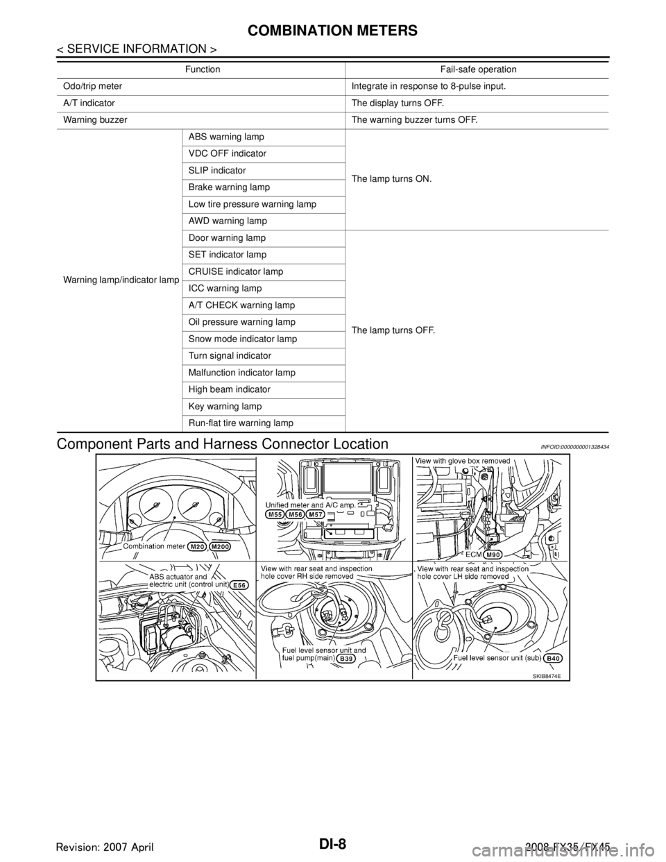
Component Parts and Harn ess Connector Location
INFOID:0000000001328434
Odo/trip meter Integrate in response to 8-pulse input.
A/T indicator The display turns OFF.
Warning buzzer The warning buzzer turns OFF.
Warning lamp/indicator lamp ABS warning lamp
The lamp turns ON.
VDC OFF indicator
SLIP indicator
Brake warning lamp
Low tire pressure warning lamp
AWD warning lamp
Door warning lamp
The lamp turns OFF.
SET indicator lamp
CRUISE indicator lamp
ICC warning lamp
A/T CHECK warning lamp
Oil pressure warning lamp
Snow mode indicator lamp
Turn signal indicator
Malfunction indicator lamp
High beam indicator
Key warning lamp
Run-flat tire warning lamp
Function Fail-safe operation
SKIB8474E
3AA93ABC3ACD3AC03ACA3AC03AC63AC53A913A773A893A873A873A8E3A773A983AC73AC93AC03AC3
3A893A873A873A8F3A773A9D3AAF3A8A3A8C3A863A9D3AAF3A8B3A8C
Page 1142 of 3924
DI-16
< SERVICE INFORMATION >
COMBINATION METERS
Perform self-diagnosis mode of combination meter. Refer to DI-14, "Self-Diagnosis Mode of Combination
Meter".
Does self-diagnosis function operate?
YES >> GO TO 2.
NO >> GO TO 3.
2.CHECK UNIFIED METER AND A/C AMP. (CONSULT-III)
Perform self-diagnosis of unified meter and A/C amp. Refer to DI-27, "
CONSULT-III Function (METER/M&A)".
Self-diagnosis results
No malfunction detected >> INSPECTION END
Malfunction detected >> Check applicable parts, and repair or replace corresponding parts.
3.CHECK POWER SUPPLY AND GROUND CIRCUIT OF COMBINATION METER
Check power supply and ground circuit of combination meter. Refer to DI-16, "
Power Supply and Ground Cir-
cuit Inspection".
OK or NG
OK >> Check odo/trip meter switch. Refer to DI-21, "Odo/Trip Meter and Illumination Control Switch
Inspection".
NG >> Repair malfunctioning part.
Symptom ChartINFOID:0000000001328443
Power Supply and Ground Circuit InspectionINFOID:0000000001328444
1.CHECK FUSE
Check for blown combination meter fuses.
OK or NG
OK >> GO TO 2.
NG >> Be sure to eliminate cause of malfunction before installing new fuse. Refer to PG-3, "
Schematic".
2.CHECK POWER SUPPLY CIRCUIT
Symptom Possible cause
Speedometer and odo/trip meter indication is malfunctioning. Refer to DI-17, "
Vehicle Speed Signal Inspection".
Tachometer indication is malfunctioning. Refer to DI-18, "
Engine Speed Signal Inspection".
Water temperature gauge indication is malfunctioning. Refer to DI-19, "
Engine Coolant Temperature Signal Inspection".
Fuel gauge indication is malfunctioning. Refer to DI-19, "
Fuel Level Sensor Signal Inspection".
Low-fuel warning lamp indication is irregular.
A/T indicator is malfunctioning. Refer to DI-49, "
A/T Indicator Is Malfunction".
Illumination control does not operate. Refer to
DI-21, "
Odo/Trip Meter and Illumination Control Switch In-
spection".
Power source Fuse No.
Battery power supply 19 ACC power supply 6
Ignition power supply 14
3AA93ABC3ACD3AC03ACA3AC03AC63AC53A913A773A893A873A873A8E3A773A983AC73AC93AC03AC3
3A893A873A873A8F3A773A9D3AAF3A8A3A8C3A863A9D3AAF3A8B3A8C
Page 1152 of 3924

DI-26
< SERVICE INFORMATION >
UNIFIED METER AND A/C AMP
UNIFIED METER AND A/C AMP
System DescriptionINFOID:0000000001328456
For the unified meter and A/C amp., the signal required for controlling the combination meter are integrated
in the A/C auto amp.
The unified meter and A/C amp. corresponds to a CONS ULT-III function (self-diagnosis results, CAN diag-
nosis support monitor, data monitor).
COMBINATION METER CONTROL FUNCTION
Unified meter and A/C amp. receives necessary information for combination meter from each unit by CAN communication.
Unified meter and A/C amp. transmits a signals with communication line (TX, RX) between unified meter and A/C amp. and combination meter.
Input/output signals between unified meter and A/C amp. and combination meter.
NOTE:
Combination meter performs fail-safe operation when unified meter and A/C amp. communication is malfunctioning. Refer to DI-5, "
Sys-
tem Description".
A/C AUTO AMP. FUNCTION
Unified meter and A/C amp. controls each operation for A/C auto amp. Regarding A/C control, refer to AT C -
24, "Description of Air Conditioner LAN Control System" in ATC section.
OTHER FUNCTIONS
Drive Computer Function
The signals required for the distance to empty (DTE) display are centralized in the unified meter and A/C
amp., converted into data, and transmitted to the disp lay unit (without NAVI) and display control unit (with
NAVI) using CAN communication.
Signal Buffer Function
Unified meter and A/C amp. transmits each signal to other units with CAN communication.
Unit Input Output
Unified meter and A/C amp. Seat belt buckle switch signal (Driver's side)
Parking brake signal
Illumination control nighttime required signal
Refuel status signal
Low-fuel warning lamp condition signal
Combination meter receive error signal
Delivery destination data signal
Combination meter specifications signal Vehicle speed signal (8-pulse)
Engine speed signal
Engine coolant temperature signal
Fuel level sensor signal (resistance value)
Malfunction indicator lamp signal
ABS warning lamp signal
Low tire pressure warning lamp signal
Run-flat tire wa
rning lamp signal
Brake warning lamp signal
A/T CHECK warning lamp signal
ICC warning lamp signal
Oil pressure switch signal
Door switch signal
AWD warning lamp signal
Key warning lamp signal
VDC OFF indicator lamp signal
SLIP indicator lamp signal
CRUISE indicator lamp signal
SET indicator lamp signal
High beam request signal
Turn indicator signal
Snow mode switch signal
ICC system display signal
Shift position indicator signal
Manual mode indicator signal
Manual mode gear position signal
CAN communication condition signal of A/T
Position lights request signal
Buzzer output signal
3AA93ABC3ACD3AC03ACA3AC03AC63AC53A913A773A893A873A873A8E3A773A983AC73AC93AC03AC3
3A893A873A873A8F3A773A9D3AAF3A8A3A8C3A863A9D3AAF3A8B3A8C
Page 1170 of 3924
DI-44
< SERVICE INFORMATION >
WARNING LAMPS
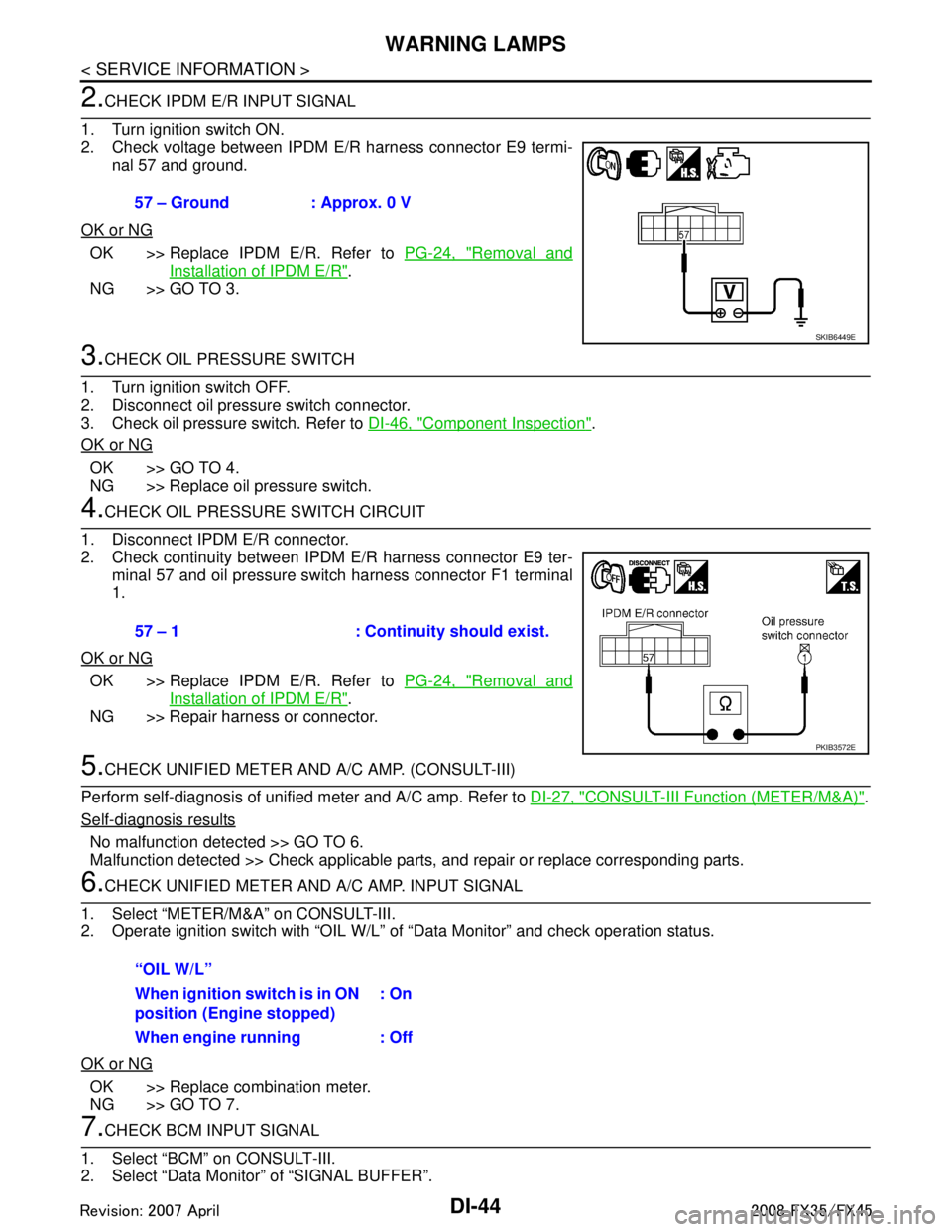
2.CHECK IPDM E/R INPUT SIGNAL
1. Turn ignition switch ON.
2. Check voltage between IPDM E/R harness connector E9 termi- nal 57 and ground.
OK or NG
OK >> Replace IPDM E/R. Refer to PG-24, "Removal and
Installation of IPDM E/R".
NG >> GO TO 3.
3.CHECK OIL PRESSURE SWITCH
1. Turn ignition switch OFF.
2. Disconnect oil pressure switch connector.
3. Check oil pressure switch. Refer to DI-46, "
Component Inspection".
OK or NG
OK >> GO TO 4.
NG >> Replace oil pressure switch.
4.CHECK OIL PRESSURE SWITCH CIRCUIT
1. Disconnect IPDM E/R connector.
2. Check continuity between IPDM E/R harness connector E9 ter- minal 57 and oil pressure switch harness connector F1 terminal
1.
OK or NG
OK >> Replace IPDM E/R. Refer to PG-24, "Removal and
Installation of IPDM E/R".
NG >> Repair harness or connector.
5.CHECK UNIFIED METER AND A/C AMP. (CONSULT-III)
Perform self-diagnosis of unified meter and A/C amp. Refer to DI-27, "
CONSULT-III Function (METER/M&A)".
Self-diagnosis results
No malfunction detected >> GO TO 6.
Malfunction detected >> Check applicable parts, and repair or replace corresponding parts.
6.CHECK UNIFIED METER AND A/C AMP. INPUT SIGNAL
1. Select “METER/M&A” on CONSULT-III.
2. Operate ignition switch with “OIL W/L” of “Data Monitor” and check operation status.
OK or NG
OK >> Replace combination meter.
NG >> GO TO 7.
7.CHECK BCM INPUT SIGNAL
1. Select “BCM” on CONSULT-III.
2. Select “Data Monitor” of “SIGNAL BUFFER”. 57 – Ground : Approx. 0 V
SKIB6449E
57 – 1 : Continuity should exist.
PKIB3572E
“OIL W/L”
When ignition switch is in ON
position (Engine stopped)
: On
When engine running : Off
3AA93ABC3ACD3AC03ACA3AC03AC63AC53A913A773A893A873A873A8E3A773A983AC73AC93AC03AC3
3A893A873A873A8F3A773A9D3AAF3A8A3A8C3A863A9D3AAF3A8B3A8C
Page 1172 of 3924
DI-46
< SERVICE INFORMATION >
WARNING LAMPS
5.CHECK IPDM E/R (CONSULT-III)
Perform self-diagnosis of IPDM E/R. Refer to PG-18, "
CONSULT-III Function (IPDM E/R)".
Self-diagnosis results
No malfunction detected >> Replace combination meter.
Malfunction detected >> Check applicable parts, and repair or replace corresponding parts.
Component InspectionINFOID:0000000001328469
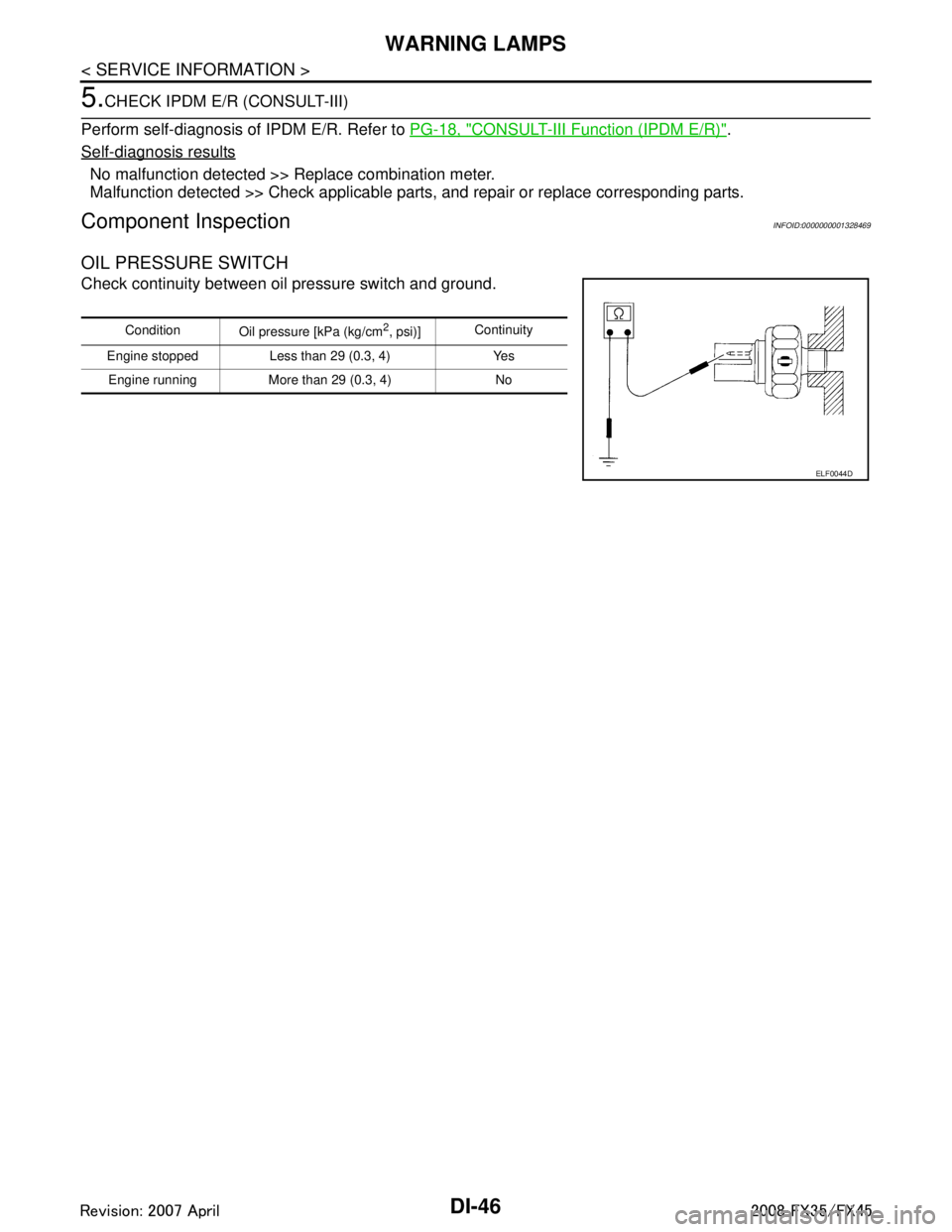
OIL PRESSURE SWITCH
Check continuity between oil pressure switch and ground.
Condition
Oil pressure [kPa (kg/cm2, psi)]Continuity
Engine stopped Less than 29 (0.3, 4) Yes Engine running More than 29 (0.3, 4) No
ELF0044D
3AA93ABC3ACD3AC03ACA3AC03AC63AC53A913A773A893A873A873A8E3A773A983AC73AC93AC03AC3
3A893A873A873A8F3A773A9D3AAF3A8A3A8C3A863A9D3AAF3A8B3A8C
Page 1176 of 3924
DI-50
< SERVICE INFORMATION >
A/T INDICATOR
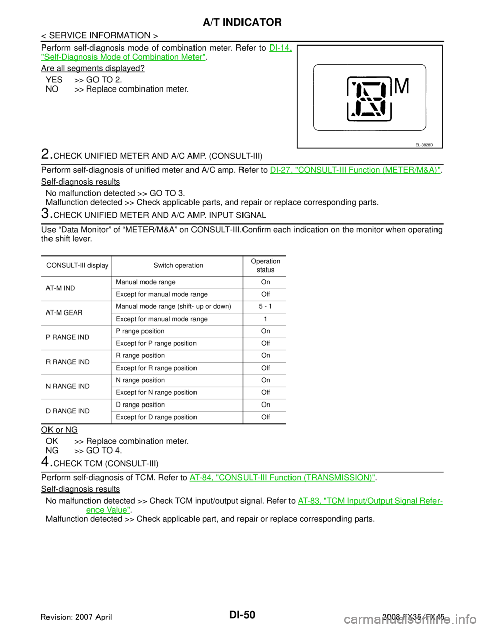
Perform self-diagnosis mode of combination meter. Refer to DI-14,
"Self-Diagnosis Mode of Combination Meter".
Are all segments displayed?
YES >> GO TO 2.
NO >> Replace combination meter.
2.CHECK UNIFIED METER AND A/C AMP. (CONSULT-III)
Perform self-diagnosis of unified meter and A/C amp. Refer to DI-27, "
CONSULT-III Function (METER/M&A)".
Self-diagnosis results
No malfunction detected >> GO TO 3.
Malfunction detected >> Check applicable parts, and repair or replace corresponding parts.
3.CHECK UNIFIED METER AND A/C AMP. INPUT SIGNAL
Use “Data Monitor” of “METER/M&A” on CONSULT-III. Confirm each indication on the monitor when operating
the shift lever.
OK or NG
OK >> Replace combination meter.
NG >> GO TO 4.
4.CHECK TCM (CONSULT-III)
Perform self-diagnosis of TCM. Refer to AT-84, "
CONSULT-III Function (TRANSMISSION)".
Self-diagnosis results
No malfunction detected >> Check TCM input/output signal. Refer to AT-83, "TCM Input/Output Signal Refer-
ence Value".
Malfunction detected >> Check applicable part, and repair or replace corresponding parts.
EL-3828D
CONSULT-III display Switch operation Operation
status
AT - M I N D Manual mode range On
Except for manual mode range Off
AT-M GEAR Manual mode range (shift- up or down) 5 - 1
Except for manual mode range 1
P RANGE IND P range position On
Except for P range position Off
R RANGE IND R range position On
Except for R range position Off
N RANGE IND N range position On
Except for N range position Off
D RANGE IND D range position On
Except for D range position Off
3AA93ABC3ACD3AC03ACA3AC03AC63AC53A913A773A893A873A873A8E3A773A983AC73AC93AC03AC3
3A893A873A873A8F3A773A9D3AAF3A8A3A8C3A863A9D3AAF3A8B3A8C