Page 3542 of 3924
SUNROOFRF-27
< SERVICE INFORMATION >
C
DE
F
G H
J
K L
M A
B
RF
N
O P
Before installing the sunroof motor assembly, be sure to place the link and wire assembly in the
symmetrical and full y closed position.
Confirm the body ground of th e noise cover is connected.
Initialization of it after instal ling the sunroof motor. Refer to RF-10, "
System Description".
PIIA5062E
PIIA5063E
3AA93ABC3ACD3AC03ACA3AC03AC63AC53A913A773A893A873A873A8E3A773A983AC73AC93AC03AC3
3A893A873A873A8F3A773A9D3AAF3A8A3A8C3A863A9D3AAF3A8B3A8C
Page 3543 of 3924
RFD-1
DRIVELINE/AXLE
CEF
G H
I
J
K L
M
SECTION RFD
A
B
RFD
N
O P
CONTENTS
REAR FINAL DRIVE
SERVICE INFORMATION .. ..........................2
PRECAUTIONS .............................................. .....2
Service Notice or Precaution ............................... ......2
PREPARATION ...................................................3
Special Service Tool ........................................... ......3
Commercial Service Tool ..........................................6
NOISE, VIBRATION AND HARSHNESS
(NVH) TROUBLESHOOTING .............................
7
NVH Troubleshooting Chart ................................ ......7
DESCRIPTION ....................................................8
Cross-Sectional View .......................................... ......8
DIFFERENTIAL GEAR OIL .................................9
Changing Differential Gear Oil ............................. .....9
Checking Differential Gear Oil ..................................9
FRONT OIL SEAL .............................................10
Removal and Installation .........................................10
SIDE OIL SEAL .................................................14
Removal and Installation .........................................14
REAR FINAL DRIVE ASSEMBLY ....................16
Removal and Installation .........................................16
Disassembly and Assembly .....................................17
SERVICE DATA AND SPECIFICATIONS
(SDS) .................................................................
38
General Specification ..............................................38
Inspection and Adjustment ......................................38
3AA93ABC3ACD3AC03ACA3AC03AC63AC53A913A773A893A873A873A8E3A773A983AC73AC93AC03AC3
3A893A873A873A8F3A773A9D3AAF3A8A3A8C3A863A9D3AAF3A8B3A8C
Page 3544 of 3924
RFD-2
< SERVICE INFORMATION >
PRECAUTIONS
SERVICE INFORMATION
PRECAUTIONS
Service Notice or PrecautionINFOID:0000000001327490
• Check for the correct installation status prior to removal or disassembly. If matching marks are required, becertain they do not interfere with the function of the parts when applied.
Overhaul should be done in a clean work area, it is preferable to work in dustproof area.
Before disassembly, using steam or white gasoline, completely remove sand and mud from the exterior of
the unit, preventing them from entering into the unit during disassembly or assembly.
Check appearance of the disassembled parts for dam age, deformation, and unusual wear. Replace them
with a new ones if necessary.
Gaskets, seals and O-rings should be replaced any time when the unit is disassembled.
In principle, tighten bolts or nuts gradually in several steps working diagonally from inside to outside. If tight-
ening sequence is specified, observe it.
Clean and flush the parts sufficiently and blow-dry them.
Be careful not to damage sliding surfaces and mating surfaces.
When applying sealant, remove the old sealant from t he mounting surface; then remove any moisture, oil,
and foreign materials from the application and mounting surfaces.
Always use shop paper for cleaning the inside of components.
Avoid using cotton gloves or shop rags to prevent entering of lint.
During assembly, observe the specified tightening tor que, and apply new gear oil, petroleum jelly, or multi-
purpose grease as specified for each vehicle, if necessary.
3AA93ABC3ACD3AC03ACA3AC03AC63AC53A913A773A893A873A873A8E3A773A983AC73AC93AC03AC3
3A893A873A873A8F3A773A9D3AAF3A8A3A8C3A863A9D3AAF3A8B3A8C
Page 3545 of 3924
PREPARATIONRFD-3
< SERVICE INFORMATION >
CEF
G H
I
J
K L
M A
B
RFD
N
O P
PREPARATION
Special Service ToolINFOID:0000000001327491
The actual shapes of Kent-Moore t ools may differ from those of special service tools illustrated here.
Tool number
(Kent-Moore No.)
Tool name Description
KV381054S0
(J-34286)
Puller Removing front oil seal
ST30720000
(J-25405)
Drift
a: 77 mm (3.03 in) dia.
b: 55.5 mm (2.185 in) dia. Installing front oil seal
Installing pinion rear bearing outer race
KV40104100
(—)
Attachment Removing side flange (For VQ35DE models)
KV40101000
(—)
Attachment Removing side flange (For VK45DE models)
ST36230000
(J-25840-A)
Sliding hammer Removing side flange
KV38100200
(J-26233)
Drift
a: 65 mm (2.56 in) dia.
b: 49 mm (1.93 in) dia. Installing side oil seal
ZZA0601D
ZZA0811D
ZZA0804D
NT159
ZZA0803D
ZZA1143D
3AA93ABC3ACD3AC03ACA3AC03AC63AC53A913A773A893A873A873A8E3A773A983AC73AC93AC03AC3
3A893A873A873A8F3A773A9D3AAF3A8A3A8C3A863A9D3AAF3A8B3A8C
Page 3546 of 3924
RFD-4
< SERVICE INFORMATION >
PREPARATION
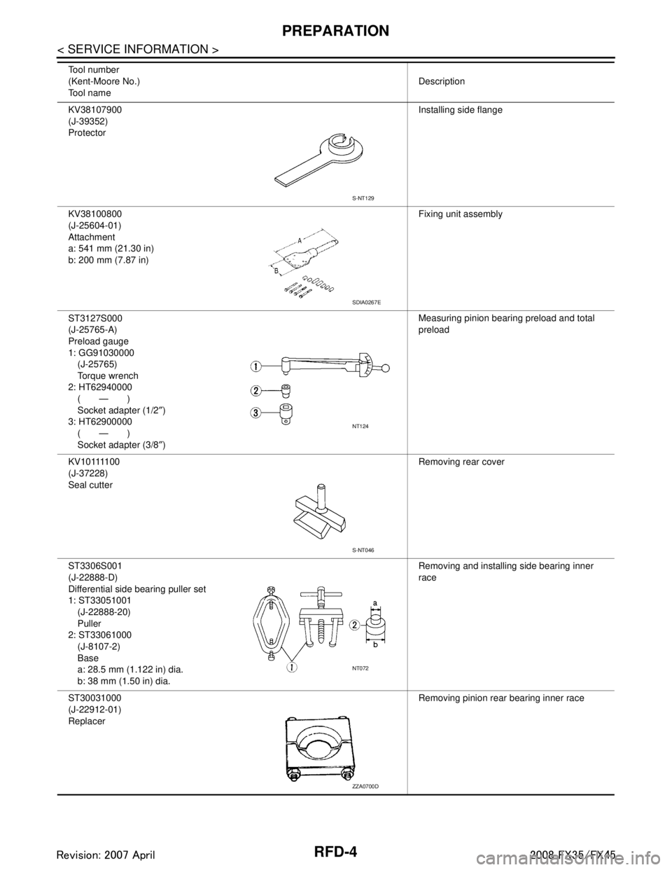
KV38107900
(J-39352)
ProtectorInstalling side flange
KV38100800
(J-25604-01)
Attachment
a: 541 mm (21.30 in)
b: 200 mm (7.87 in) Fixing unit assembly
ST3127S000
(J-25765-A)
Preload gauge
1: GG91030000 (J-25765)
Torque wrench
2: HT62940000 (—)
Socket adapter (1/2 ″)
3: HT62900000 (—)
Socket adapter (3/8 ″) Measuring pinion bearing preload and total
preload
K V 1 0 1111 0 0
(J-37228)
Seal cutter Removing rear cover
ST3306S001
(J-22888-D)
Differential side bearing puller set
1: ST33051001 (J-22888-20)
Puller
2: ST33061000 (J-8107-2)
Base
a: 28.5 mm (1.122 in) dia.
b: 38 mm (1.50 in) dia. Removing and installing side bearing inner
race
ST30031000
(J-22912-01)
Replacer Removing pinion rear bearing inner race
Tool number
(Kent-Moore No.)
Tool name
Description
S-NT129
SDIA0267E
NT124
S-NT046
NT072
ZZA0700D
3AA93ABC3ACD3AC03ACA3AC03AC63AC53A913A773A893A873A873A8E3A773A983AC73AC93AC03AC3
3A893A873A873A8F3A773A9D3AAF3A8A3A8C3A863A9D3AAF3A8B3A8C
Page 3547 of 3924
PREPARATIONRFD-5
< SERVICE INFORMATION >
CEF
G H
I
J
K L
M A
B
RFD
N
O P
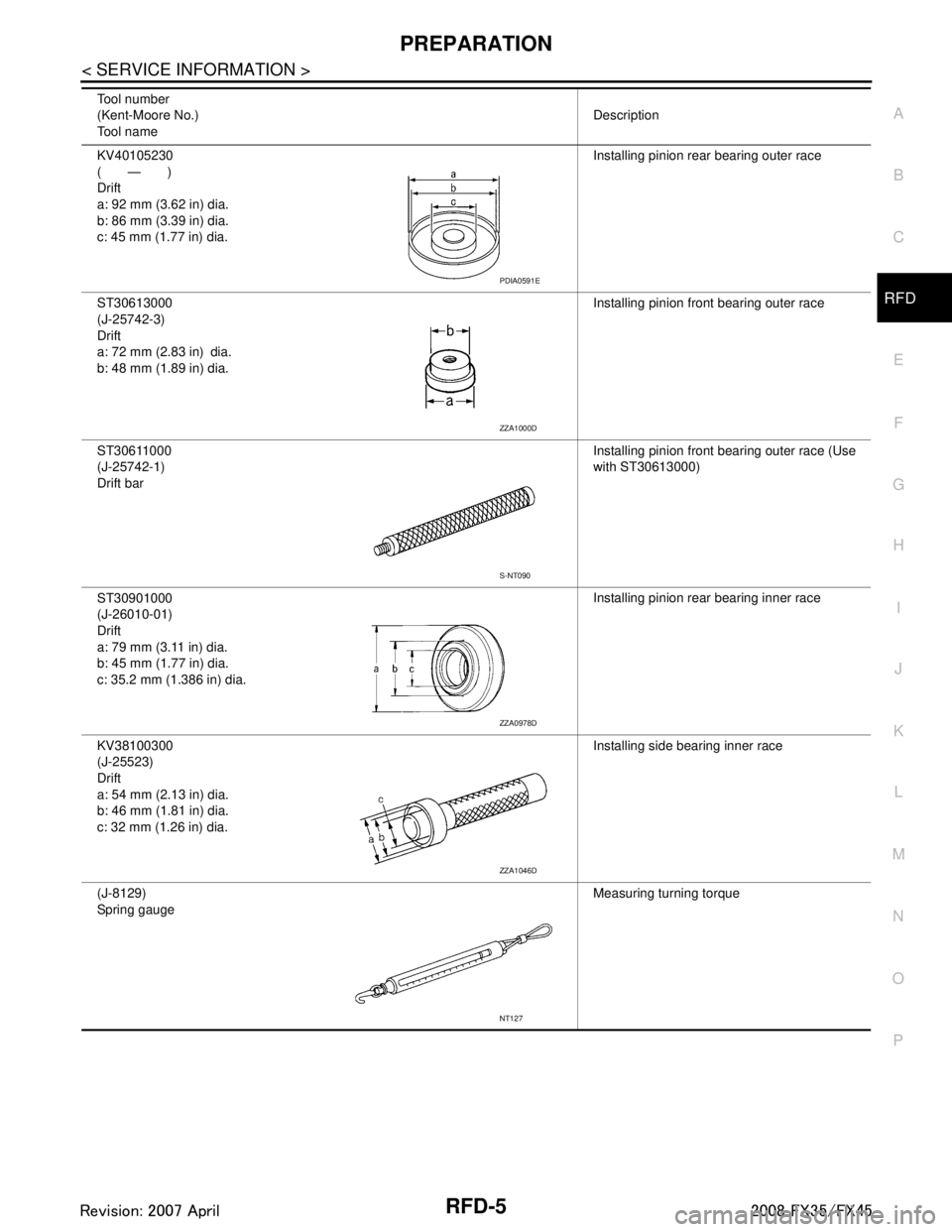
KV40105230
(—)
Drift
a: 92 mm (3.62 in) dia.
b: 86 mm (3.39 in) dia.
c: 45 mm (1.77 in) dia. Installing pinion rear bearing outer race
ST30613000
(J-25742-3)
Drift
a: 72 mm (2.83 in) dia.
b: 48 mm (1.89 in) dia. Installing pinion front bearing outer race
ST30611000
(J-25742-1)
Drift bar Installing pinion front bearing outer race (Use
with ST30613000)
ST30901000
(J-26010-01)
Drift
a: 79 mm (3.11 in) dia.
b: 45 mm (1.77 in) dia.
c: 35.2 mm (1.386 in) dia. Installing pinion rear bearing inner race
KV38100300
(J-25523)
Drift
a: 54 mm (2.13 in) dia.
b: 46 mm (1.81 in) dia.
c: 32 mm (1.26 in) dia. Installing side bearing inner race
(J-8129)
Spring gauge Measuring turning torque
Tool number
(Kent-Moore No.)
Tool name
Description
PDIA0591E
ZZA1000D
S-NT090
ZZA0978D
ZZA1046D
NT127
3AA93ABC3ACD3AC03ACA3AC03AC63AC53A913A773A893A873A873A8E3A773A983AC73AC93AC03AC3
3A893A873A873A8F3A773A9D3AAF3A8A3A8C3A863A9D3AAF3A8B3A8C
Page 3548 of 3924
RFD-6
< SERVICE INFORMATION >
PREPARATION
Commercial Service Tool
INFOID:0000000001327492
(J-34309)
Differential shim selector tool Adjusting bearing preload and pinion gear
height
(J-25269-4)
Side bearing disc (2 Req'd) Selecting pinion height adjusting washer
Tool number
(Kent-Moore No.)
Tool name
Description
NT134
NT136
Tool name
Description
Flange wrench Removing and installing drive pinion lock nut
Spacer
a: 60 mm (2.36 in) dia.
b: 36 mm (1.42 in) dia.
c: 30 mm (1.18 in) Installing pinion front bearing inner race
Power tool Loosening nuts and bolts
NT035
ZZA1133D
PBIC0190E
3AA93ABC3ACD3AC03ACA3AC03AC63AC53A913A773A893A873A873A8E3A773A983AC73AC93AC03AC3
3A893A873A873A8F3A773A9D3AAF3A8A3A8C3A863A9D3AAF3A8B3A8C
Page 3549 of 3924
NOISE, VIBRATION AND HARSHNESS (NVH) TROUBLESHOOTINGRFD-7
< SERVICE INFORMATION >
CEF
G H
I
J
K L
M A
B
RFD
N
O P
NOISE, VIBRATION AND HARSHN ESS (NVH) TROUBLESHOOTING
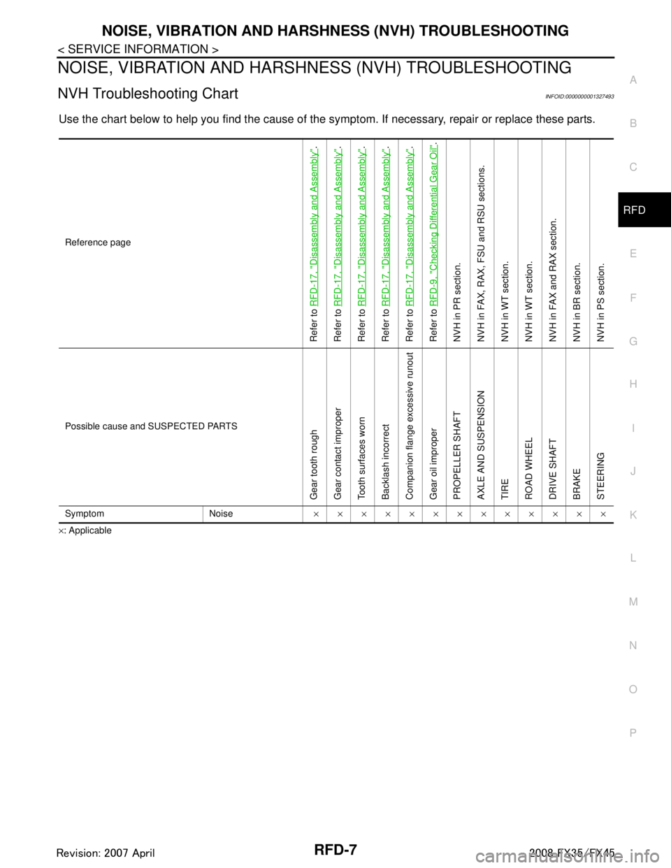
NVH Troubleshooting ChartINFOID:0000000001327493
Use the chart below to help you find t he cause of the symptom. If necessary, repair or replace these parts.
×: ApplicableReference page
Refer to
RFD-17, "
Disassembly and Assembly
".
Refer to RFD-17, "
Disassembly and Assembly
".
Refer to RFD-17, "
Disassembly and Assembly
".
Refer to RFD-17, "
Disassembly and Assembly
".
Refer to RFD-17, "
Disassembly and Assembly
".
Refer to RFD-9, "
Checking Differential Gear Oil
".
NVH in PR section.
NVH in FAX, RAX, FSU and RSU sections.
NVH in WT section.
NVH in WT section.
NVH in FAX and RAX section.
NVH in BR section.
NVH in PS section.
Possible cause and SUSPECTED PARTS
Gear tooth rough
Gear contact improper
Tooth surfaces worn
Backlash incorrect
Companion flange excessive runout
Gear oil improper
PROPELLER SHAFT
AXLE AND SUSPENSION
TIRE
ROAD WHEEL
DRIVE SHAFT
BRAKE
STEERING
Symptom Noise ×××××××××××××
3AA93ABC3ACD3AC03ACA3AC03AC63AC53A913A773A893A873A873A8E3A773A983AC73AC93AC03AC3
3A893A873A873A8F3A773A9D3AAF3A8A3A8C3A863A9D3AAF3A8B3A8C