2008 INFINITI FX35 battery location
[x] Cancel search: battery locationPage 3100 of 3924
![INFINITI FX35 2008 Service Manual
LAN-80
< SERVICE INFORMATION >[CAN]
TROUBLE DIAGNOSIS
2.CHECK HARNESS FOR OPEN CIRCUIT
1. Disconnect the connector of driver seat control unit.
2. Check the resistance between the driver seat contro INFINITI FX35 2008 Service Manual
LAN-80
< SERVICE INFORMATION >[CAN]
TROUBLE DIAGNOSIS
2.CHECK HARNESS FOR OPEN CIRCUIT
1. Disconnect the connector of driver seat control unit.
2. Check the resistance between the driver seat contro](/manual-img/42/57017/w960_57017-3099.png)
LAN-80
< SERVICE INFORMATION >[CAN]
TROUBLE DIAGNOSIS
2.CHECK HARNESS FOR OPEN CIRCUIT
1. Disconnect the connector of driver seat control unit.
2. Check the resistance between the driver seat control unit harness connector terminals.
OK or NG
OK >> GO TO 3.
NG >> Repair the driver seat control unit branch line.
3.CHECK POWER SUPPLY AND GROUND CIRCUIT
Check the power supply and the ground circuit of the driver seat control unit. Refer to SE-18, "
Schematic".
OK or NG
OK >> Present error: Replace the driver seat control unit. Refer to SE-16, "Component Parts and Har-
ness Connector Location".
Past error: Error was detected in t he driver seat control unit branch line.
NG >> Repair the power supply and the ground circuit.
IPDM E/R Branch Line CircuitINFOID:0000000001328668
INSPECTION PROCEDURE
1.CHECK CONNECTOR
1. Turn the ignition switch OFF.
2. Disconnect the battery cable from the negative terminal.
3. Check the following terminals and connectors fo r damage, bend and loose connection (unit side and con-
nector side).
- IPDM E/R
- Harness connector E205
- Harness connector B5
OK or NG
OK >> GO TO 2.
NG >> Repair the terminal and connector.
2.CHECK HARNESS FOR OPEN CIRCUIT
1. Disconnect the connector of IPDM E/R.
2. Check the resistance between the IPDM E/R harness connector terminals.
OK or NG
OK >> GO TO 3.
NG >> Repair the IPDM E/R branch line.
3.CHECK POWER SUPPLY AND GROUND CIRCUIT
Check the power supply and the ground circuit of the IPDM E/R. Refer to PG-23, "
IPDM E/R Power/Ground
Circuit Inspection".
OK or NG
OK >> Present error: Replace the IPDM E/R. Refer to PG-24, "Removal and Installation of IPDM E/R".
Past error: Error was detected in the IPDM E/R branch line.
NG >> Repair the power supply and the ground circuit.
Driver seat control unit harness connector Resistance (Ω)
Connector No. Terminal No.
B152 14 15 Approx. 54 – 66
IPDM E/R harness connector Resistance (Ω)
Connector No. Terminal No.
E9 48 49 Approx. 108 – 132
3AA93ABC3ACD3AC03ACA3AC03AC63AC53A913A773A893A873A873A8E3A773A983AC73AC93AC03AC3
3A893A873A873A8F3A773A9D3AAF3A8A3A8C3A863A9D3AAF3A8B3A8C
Page 3107 of 3924
HEADLAMP - XENON TYPE -LT-5
< SERVICE INFORMATION >
C
DE
F
G H
I
J
L
M A
B
LT
N
O P
HEADLAMP - XENON TYPE -
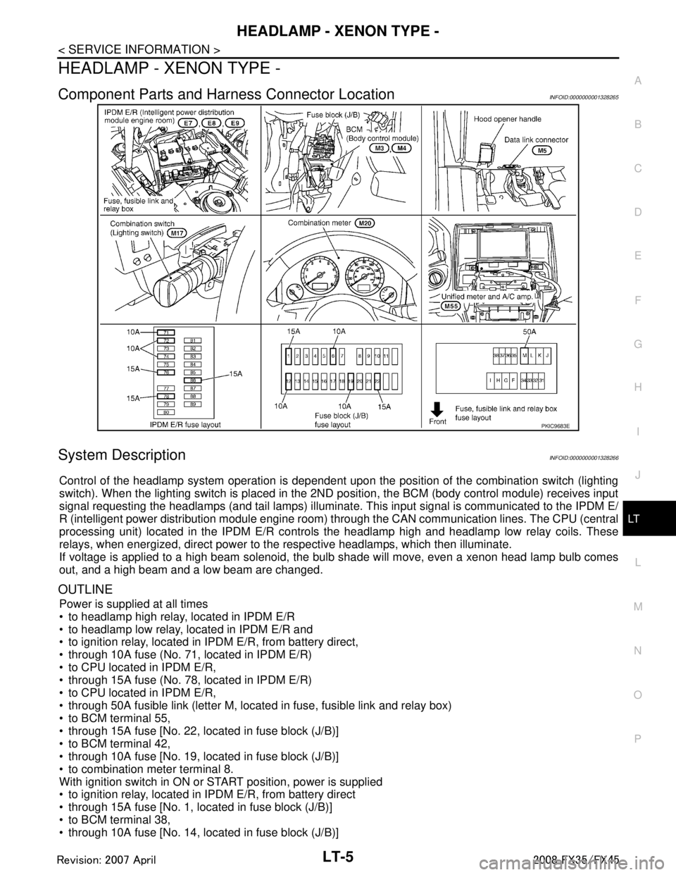
Component Parts and Har ness Connector LocationINFOID:0000000001328265
System DescriptionINFOID:0000000001328266
Control of the headlamp system operation is dependent upon t he position of the combination switch (lighting
switch). When the lighting switch is placed in the 2ND position, the BCM (body control module) receives input
signal requesting the headlamps (and tail lamps) illuminate. This input signal is communicated to the IPDM E/
R (intelligent power distribution module engine room) through the CAN communication lines. The CPU (central
processing unit) located in the IPDM E/R contro ls the headlamp high and headlamp low relay coils. These
relays, when energized, direct power to the respective headlamps, which then illuminate.
If voltage is applied to a high beam solenoid, the bulb shade will move, even a xenon head lamp bulb comes
out, and a high beam and a low beam are changed.
OUTLINE
Power is supplied at all times
to headlamp high relay, located in IPDM E/R
to headlamp low relay, located in IPDM E/R and
to ignition relay, located in IPDM E/R, from battery direct,
through 10A fuse (No. 71, located in IPDM E/R)
to CPU located in IPDM E/R,
through 15A fuse (No. 78, located in IPDM E/R)
to CPU located in IPDM E/R,
through 50A fusible link (letter M, located in fuse, fusible link and relay box)
to BCM terminal 55,
through 15A fuse [No. 22, located in fuse block (J/B)]
to BCM terminal 42,
through 10A fuse [No. 19, located in fuse block (J/B)]
to combination meter terminal 8.
With ignition switch in ON or START position, power is supplied
to ignition relay, located in IPDM E/R, from battery direct
through 15A fuse [No. 1, located in fuse block (J/B)]
to BCM terminal 38,
through 10A fuse [No. 14, located in fuse block (J/B)]
PKIC9683E
3AA93ABC3ACD3AC03ACA3AC03AC63AC53A913A773A893A873A873A8E3A773A983AC73AC93AC03AC3
3A893A873A873A8F3A773A9D3AAF3A8A3A8C3A863A9D3AAF3A8B3A8C
Page 3132 of 3924
LT-30
< SERVICE INFORMATION >
HEADLAMP - XENON TYPE -
After installing bulb, be sure to install plastic cap and bulb socket securely to insure watertight-
ness.
Removal and InstallationINFOID:0000000001328289
REMOVAL
1. Disconnect the battery cable from the negative terminal or remove power fuse.
2. Remove front bumper fascia assembly. Refer to EI-14, "
Compo-
nent Parts Location".
3. Remove headlamp mounting bolts and nut.
4. Remove plastics bumper bracket, then pull headlamp toward vehicle front, disconnect connector, and remove headlamp.
INSTALLATION
Installation is the reverse order of removal.
NOTE:
After installation, perform aiming adjustment. Refer to LT-27, "
Aiming Adjustment".
Disassembly and AssemblyINFOID:0000000001328290
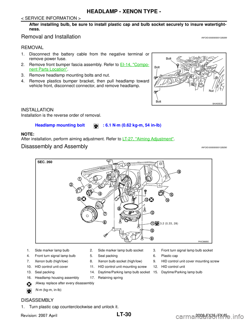
DISASSEMBLY
1. Turn plastic cap counterclockwise and unlock it.
SKIA5553E
Headlamp mounting bolt : 6.1 N·m (0.62 kg-m, 54 in-lb)
1. Side marker lamp bulb 2. Side marker lamp bulb socket 3. Front turn signal lamp bulb socket
4. Front turn signal lamp bulb 5. Seal packing 6. Plastic cap
7. Xenon bulb (high/low) 8. Xenon bulb socket (high/low) 9. HID control unit cover mounting screw
10. HID control unit cover 11. HID control unit mounting screw 12. HID control unit
13. Seal packing 14. Daytime/Parking lamp bulb socket 15. Daytime/Parking lamp bulb
16. Headlamp housing assembly 17. Retaining spring
:Alway replace after every disassembly
:N·m (kg-m, in-lb)
PKIC9685E
3AA93ABC3ACD3AC03ACA3AC03AC63AC53A913A773A893A873A873A8E3A773A983AC73AC93AC03AC3
3A893A873A873A8F3A773A9D3AAF3A8A3A8C3A863A9D3AAF3A8B3A8C
Page 3168 of 3924
LT-66
< SERVICE INFORMATION >
FRONT FOG LAMP
FRONT FOG LAMP
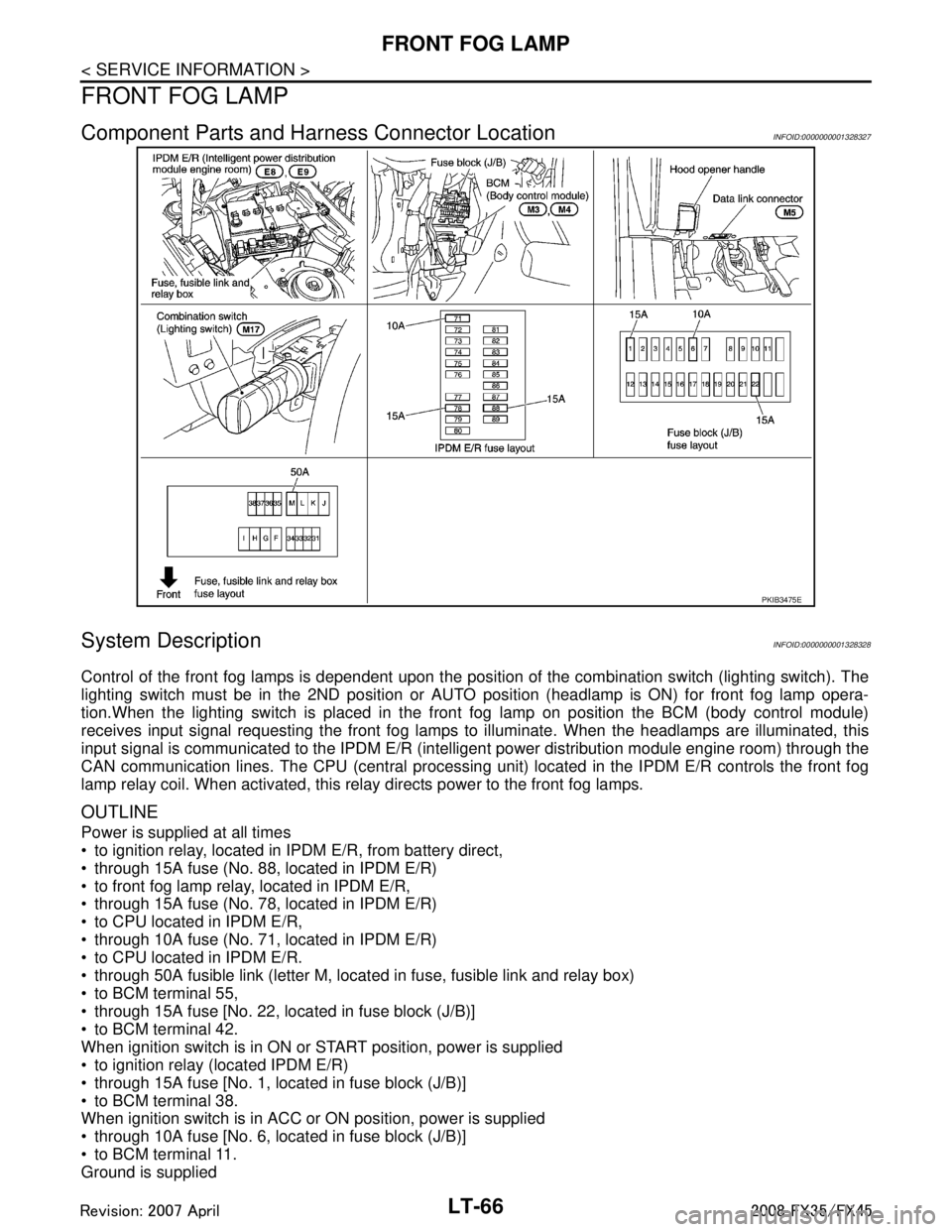
Component Parts and Harness Connector LocationINFOID:0000000001328327
System DescriptionINFOID:0000000001328328
Control of the front fog lamps is dependent upon the position of the combination switch (lighting switch). The
lighting switch must be in the 2ND position or AUTO position (headlamp is ON) for front fog lamp opera-
tion.When the lighting switch is placed in the front fog lamp on position the BCM (body control module)
receives input signal requesting the front fog lamps to illuminate. When the headlamps are illuminated, this
input signal is communicated to the IPDM E/R (inte lligent power distribution module engine room) through the
CAN communication lines. The CPU (central processing unit) located in the IPDM E/R controls the front fog
lamp relay coil. When activated, this relay directs power to the front fog lamps.
OUTLINE
Power is supplied at all times
to ignition relay, located in IP DM E/R, from battery direct,
through 15A fuse (No. 88, located in IPDM E/R)
to front fog lamp relay, located in IPDM E/R,
through 15A fuse (No. 78, located in IPDM E/R)
to CPU located in IPDM E/R,
through 10A fuse (No. 71, located in IPDM E/R)
to CPU located in IPDM E/R.
through 50A fusible link (letter M, located in fuse, fusible link and relay box)
to BCM terminal 55,
through 15A fuse [No. 22, located in fuse block (J/B)]
to BCM terminal 42.
When ignition switch is in ON or START position, power is supplied
to ignition relay (located IPDM E/R)
through 15A fuse [No. 1, located in fuse block (J/B)]
to BCM terminal 38.
When ignition switch is in ACC or ON position, power is supplied
through 10A fuse [No. 6, located in fuse block (J/B)]
to BCM terminal 11.
Ground is supplied
PKIB3475E
3AA93ABC3ACD3AC03ACA3AC03AC63AC53A913A773A893A873A873A8E3A773A983AC73AC93AC03AC3
3A893A873A873A8F3A773A9D3AAF3A8A3A8C3A863A9D3AAF3A8B3A8C
Page 3220 of 3924
LT-118
< SERVICE INFORMATION >
PARKING, LICENSE PLATE AND TAIL LAMPS
PARKING, LICENSE PLATE AND TAIL LAMPS
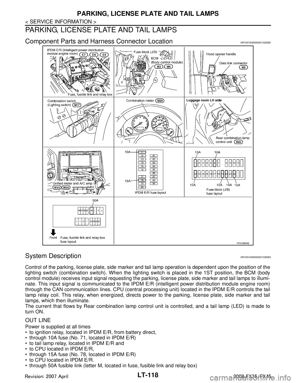
Component Parts and Harness Connector LocationINFOID:0000000001328382
System DescriptionINFOID:0000000001328383
Control of the parking, license plate, side marker and tail lamp operation is dependent upon the position of the
lighting switch (combination switch). When the lighting switch is placed in the 1ST position, the BCM (body
control module) receives input signal requesting the parki ng, license plate, side marker and tail lamps to illumi-
nate. This input signal is communicated to the IPDM E/R (intelligent power distribution module engine room)
through the CAN communication lines. CPU (central processi ng unit) located in the IPDM E/R controls the tail
lamp relay coil. This relay, when energized, directs pow er to the parking, license plate, side marker and tail
lamps, which then illuminate.
The current that flows by Rear combination lamp cont rol unit is controlled, and a tail lamp (LED) is made to
turn ON.
OUT LINE
Power is supplied at all times
to ignition relay, located in IP DM E/R, from battery direct,
through 10A fuse (No. 71, located in IPDM E/R)
to tail lamp relay, located in IPDM E/R and
to CPU located in IPDM E/R,
through 15A fuse (No. 78, located in IPDM E/R)
to CPU located in IPDM E/R.
through 50A fusible link (letter M, located in fuse, fusible link and relay box)
PKIC9694E
3AA93ABC3ACD3AC03ACA3AC03AC63AC53A913A773A893A873A873A8E3A773A983AC73AC93AC03AC3
3A893A873A873A8F3A773A9D3AAF3A8A3A8C3A863A9D3AAF3A8B3A8C
Page 3531 of 3924
![INFINITI FX35 2008 Service Manual
RF-16
< SERVICE INFORMATION >
SUNROOF
Check BCM Power Suppl y and Ground Circuit
INFOID:0000000001328043
1.CHECK FUSE
Check 15A fuse [No.1, located in the fuse block (J/B)]
Check 15A fuse [No.22, INFINITI FX35 2008 Service Manual
RF-16
< SERVICE INFORMATION >
SUNROOF
Check BCM Power Suppl y and Ground Circuit
INFOID:0000000001328043
1.CHECK FUSE
Check 15A fuse [No.1, located in the fuse block (J/B)]
Check 15A fuse [No.22,](/manual-img/42/57017/w960_57017-3530.png)
RF-16
< SERVICE INFORMATION >
SUNROOF
Check BCM Power Suppl y and Ground Circuit
INFOID:0000000001328043
1.CHECK FUSE
Check 15A fuse [No.1, located in the fuse block (J/B)]
Check 15A fuse [No.22, located in the fuse block (J/B)]
Check 50A fusible link (letter M, located in the fuse and fusible link box).
NOTE:
Refer to RF-10, "
Component Parts and Harness Connector Location".
OK or NG
OK >> GO TO 2.
NG >> If fuse is blown out, be sure to eliminate cause of malfunction before installing new fuse. Refer to RF-10, "
Component Parts and Harness Connector Location".
2.CHECK POWER SUPPLY CIRCUIT
1. Turn ignition switch ON.
2. Check voltage between BCM connector M3, M4 terminal 38, 42, 55 and ground.
OK or NG
OK >> GO TO 3.
NG >> Check BCM power supply circuit for open or short.
3.CHECK GROUND CIRCUIT
1. Turn ignition switch OFF.
2. Disconnect BCM connector.
3. Check continuity between BCM connector M4 terminal 49, 52 and ground.
OK or NG
OK >> Power supply and ground circuit are OK.
NG >> Check BCM ground circuit for open or short.
Check Sunroof Motor Assembly Power Supply and Ground CircuitINFOID:0000000001328044
1.CHECK POWER SUPPLY CIRCUIT
1. Turn ignition switch ON.
2. Check voltage between sunroof motor assembly connector R5 terminal 7, 9 and ground.
Retained power operation does not operate
properly. 1. Check the retained power operation mode setting.
RF-152. Check door switch.RF-19
3. Replace sunroof motor assembly.RF-22
Sunroof does not operate the interruption de-
tection function.Replace sunroof motor assembly.
RF-22
Symptom Diagnostic procedure and repair order Refer to page
38 (W/L) – Ground : Battery voltage
42 (L/R) – Ground : Battery voltage
55 (G) – Ground : Battery voltage
PIIA6160E
49 (B) – Ground : Continuity should exist.
52 (B) – Ground : Continuity should exist.
PIIA6161E
3AA93ABC3ACD3AC03ACA3AC03AC63AC53A913A773A893A873A873A8E3A773A983AC73AC93AC03AC3
3A893A873A873A8F3A773A9D3AAF3A8A3A8C3A863A9D3AAF3A8B3A8C
Page 3603 of 3924
SB-4
< SERVICE INFORMATION >
SEAT BELTS
2. Remove the anchor bolt.
3. Remove the seat cushion outer finisher cover, and remove the anchor bolt.NOTE:
Set the front and rear cushion lifter to the lower position.
4. Disconnect the belt tension sensor connector (passenger side only).
5. Remove the center pillar upper and lower garnish. Refer to EI-38, "
Component Parts Location".
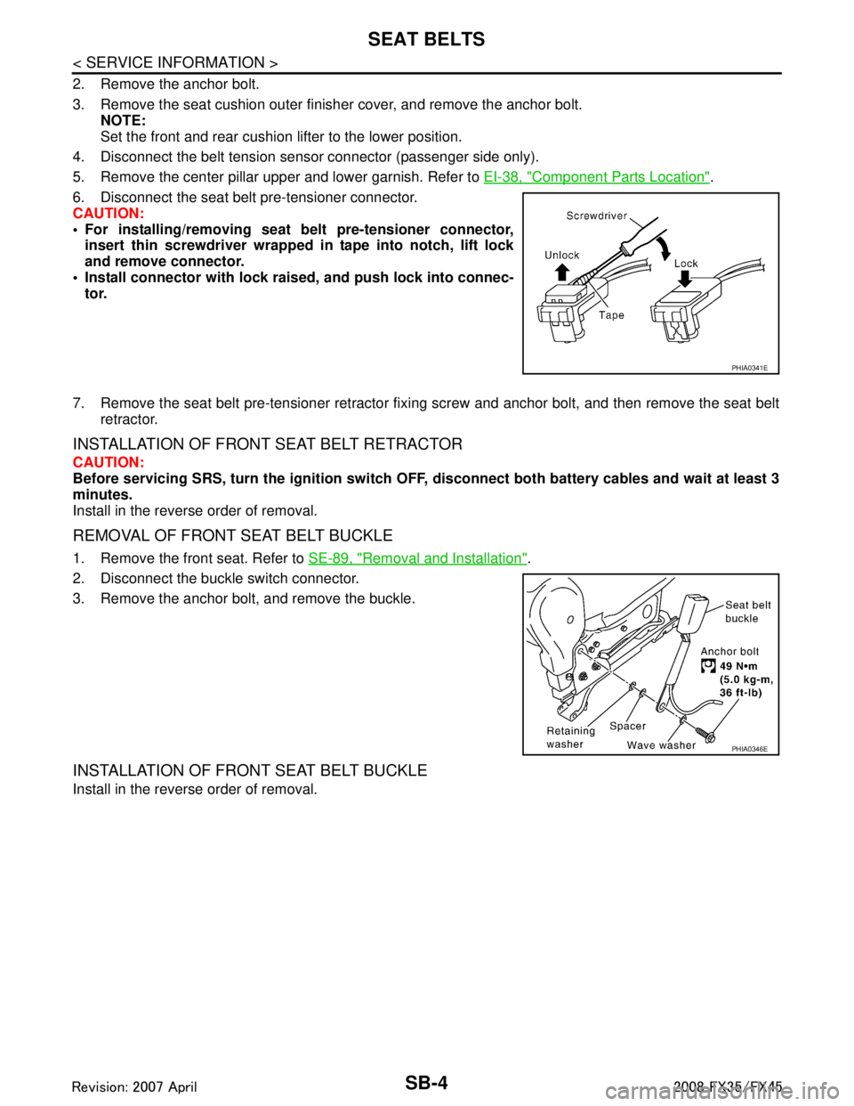
6. Disconnect the seat belt pre-tensioner connector.
CAUTION:
For installing/removing seat belt pre-tensioner connector, insert thin screwdriver wrapped in tape into notch, lift lock
and remove connector.
Install connector with lock ra ised, and push lock into connec-
tor.
7. Remove the seat belt pre-tensioner retractor fixi ng screw and anchor bolt, and then remove the seat belt
retractor.
INSTALLATION OF FRONT SEAT BELT RETRACTOR
CAUTION:
Before servicing SRS, turn the igni tion switch OFF, disconnect both battery cables and wait at least 3
minutes.
Install in the reverse order of removal.
REMOVAL OF FRONT SEAT BELT BUCKLE
1. Remove the front seat. Refer to SE-89, "Removal and Installation".
2. Disconnect the buckle switch connector.
3. Remove the anchor bolt, and remove the buckle.
INSTALLATION OF FRONT SEAT BELT BUCKLE
Install in the reverse order of removal.
PHIA0341E
PHIA0346E
3AA93ABC3ACD3AC03ACA3AC03AC63AC53A913A773A893A873A873A8E3A773A983AC73AC93AC03AC3
3A893A873A873A8F3A773A9D3AAF3A8A3A8C3A863A9D3AAF3A8B3A8C
Page 3677 of 3924
SE-38
< SERVICE INFORMATION >
AUTOMATIC DRIVE POSITIONER
NOTE:
After the setting is registered, the new setting is effective, even if the battery is disconnected.
CHECK POWER SUPPLY AND GROUND
1.CHECK FUSE
Check if any of the following fuses in the BCM are blown.
Check 50A fusible link (letter M, located in the fuse and fusible link box.)
Check 15A fuse [No.22, located in the fuse block (J/B)]
Check 10A fuse [No.1, located in the fuse block (J/B)]
Check 10A fuse [No.6, located in the fuse block (J/B)]
NOTE:
Refer to SE-16, "
Component Parts and Harness Connector Location".
OK or NG
OK >> GO TO 2.
NG >> If fuse is blown out, be sure to eliminate cause of malfunction before installing new fuse. Refer to SE-16, "
Component Parts and Harness Connector Location".
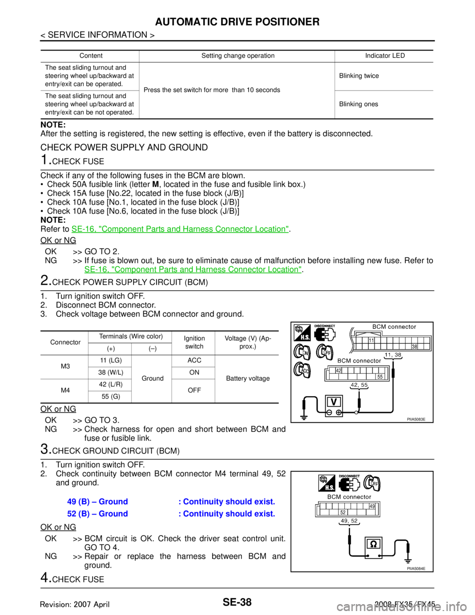
2.CHECK POWER SUPPLY CIRCUIT (BCM)
1. Turn ignition switch OFF.
2. Disconnect BCM connector.
3. Check voltage between BCM connector and ground.
OK or NG
OK >> GO TO 3.
NG >> Check harness for open and short between BCM and fuse or fusible link.
3.CHECK GROUND CIRCUIT (BCM)
1. Turn ignition switch OFF.
2. Check continuity between BCM connector M4 terminal 49, 52 and ground.
OK or NG
OK >> BCM circuit is OK. Check the driver seat control unit. GO TO 4.
NG >> Repair or replace the harness between BCM and ground.
4.CHECK FUSE
Content Setting change operation Indicator LED
The seat sliding turnout and
steering wheel up/backward at
entry/exit can be operated. Press the set switch for more than 10 seconds Blinking twice
The seat sliding turnout and
steering wheel up/backward at
entry/exit can be not operated. Blinking ones
Connector
Terminals (Wire color)
Ignition
switch Voltage (V) (Ap-
prox.)
(+) (–)
M3 11 ( L G )
Ground ACC
Battery voltage
38 (W/L) ON
M4 42 (L/R)
OFF
55 (G)
PIIA5083E
49 (B) – Ground : Continuity should exist.
52 (B) – Ground : Continuity should exist.
PIIA5084E
3AA93ABC3ACD3AC03ACA3AC03AC63AC53A913A773A893A873A873A8E3A773A983AC73AC93AC03AC3
3A893A873A873A8F3A773A9D3AAF3A8A3A8C3A863A9D3AAF3A8B3A8C