Page 3182 of 3924

LT-80
< SERVICE INFORMATION >
TURN SIGNAL AND HAZARD WARNING LAMPS
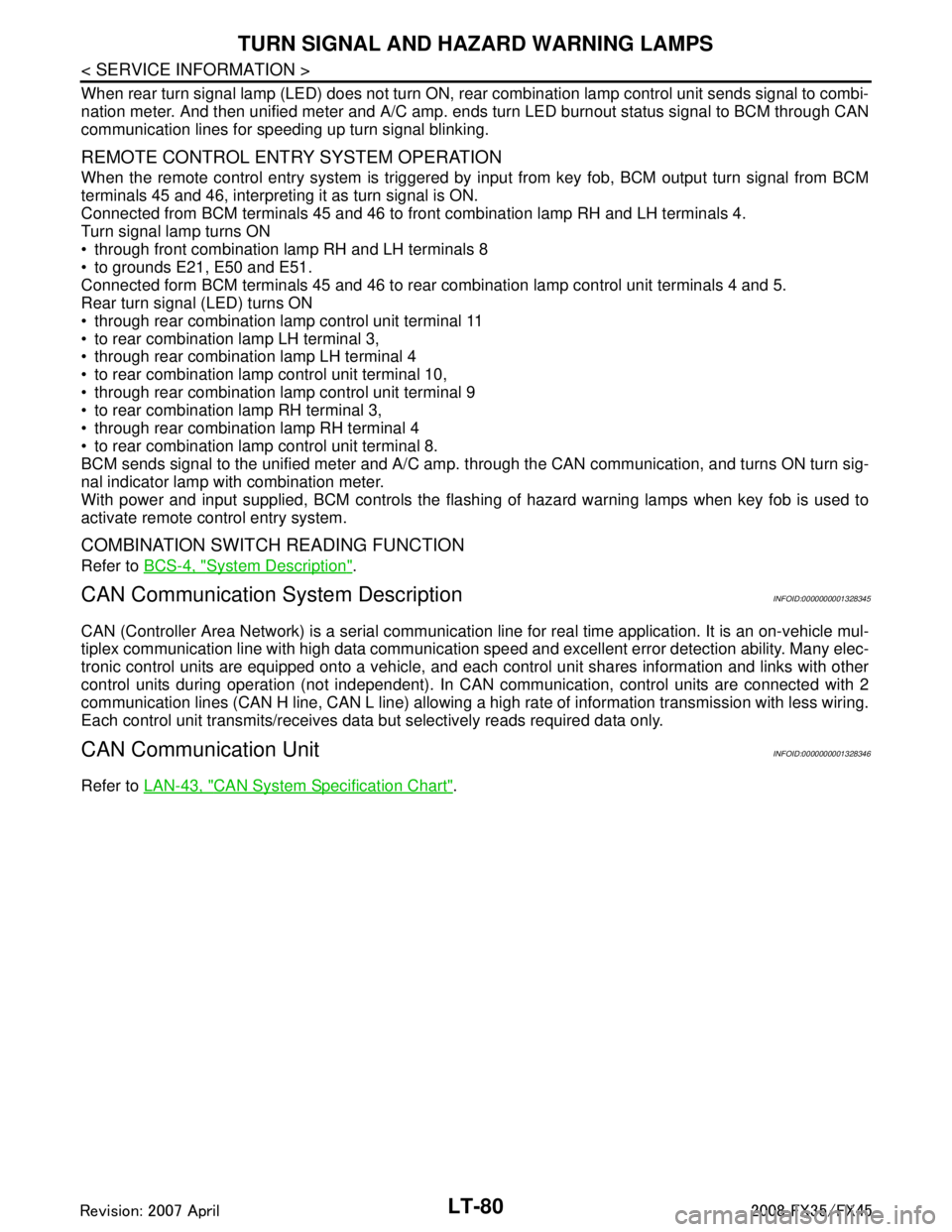
When rear turn signal lamp (LED) does not turn ON, rear combination lamp control unit sends s\
ignal to combi-
nation meter. And then unified meter and A/C amp. ends turn LED burnout status signal to BCM through CAN
communication lines for speeding up turn signal blinking.
REMOTE CONTROL ENTRY SYSTEM OPERATION
When the remote control entry system is triggered by i nput from key fob, BCM output turn signal from BCM
terminals 45 and 46, interpreting it as turn signal is ON.
Connected from BCM terminals 45 and 46 to front combination lamp RH and LH terminals 4.
Turn signal lamp turns ON
through front combination lamp RH and LH terminals 8
to grounds E21, E50 and E51.
Connected form BCM terminals 45 and 46 to rear combination lamp control unit terminals 4 and 5.
Rear turn signal (LED) turns ON
through rear combination lamp control unit terminal 11
to rear combination lamp LH terminal 3,
through rear combination lamp LH terminal 4
to rear combination lamp control unit terminal 10,
through rear combination lamp control unit terminal 9
to rear combination lamp RH terminal 3,
through rear combination lamp RH terminal 4
to rear combination lamp control unit terminal 8.
BCM sends signal to the unified meter and A/C amp. through the CAN communication, and turns ON turn sig-
nal indicator lamp with combination meter.
With power and input supplied, BCM controls the flashing of hazard warning lamps when key fob is used to
activate remote control entry system.
COMBINATION SWITCH READING FUNCTION
Refer to BCS-4, "System Description".
CAN Communication System DescriptionINFOID:0000000001328345
CAN (Controller Area Network) is a serial communication line for real time application. It is an on-vehicle mul-
tiplex communication line with high data communication s peed and excellent error detection ability. Many elec-
tronic control units are equipped onto a vehicle, and each control unit shares information and links with other
control units during operation (not independent). In CA N communication, control units are connected with 2
communication lines (CAN H line, CAN L line) allowing a high rate of information transmission with less wiring.
Each control unit transmits/receives data but selectively reads required data only.
CAN Communication UnitINFOID:0000000001328346
Refer to LAN-43, "CAN System Specification Chart".
3AA93ABC3ACD3AC03ACA3AC03AC63AC53A913A773A893A873A873A8E3A773A983AC73AC93AC03AC3
3A893A873A873A8F3A773A9D3AAF3A8A3A8C3A863A9D3AAF3A8B3A8C
Page 3183 of 3924
TURN SIGNAL AND HAZARD WARNING LAMPSLT-81
< SERVICE INFORMATION >
C
DE
F
G H
I
J
L
M A
B
LT
N
O P
SchematicINFOID:0000000001328347
TKWM4305E
3AA93ABC3ACD3AC03ACA3AC03AC63AC53A913A773A893A873A873A8E3A773A983AC73AC93AC03AC3
3A893A873A873A8F3A773A9D3AAF3A8A3A8C3A863A9D3AAF3A8B3A8C
Page 3184 of 3924
LT-82
< SERVICE INFORMATION >
TURN SIGNAL AND HAZARD WARNING LAMPS
Wiring Diagram - TURN -
INFOID:0000000001328348
TKWM4306E
3AA93ABC3ACD3AC03ACA3AC03AC63AC53A913A773A893A873A873A8E3A773A983AC73AC93AC03AC3
3A893A873A873A8F3A773A9D3AAF3A8A3A8C3A863A9D3AAF3A8B3A8C
Page 3185 of 3924
TURN SIGNAL AND HAZARD WARNING LAMPSLT-83
< SERVICE INFORMATION >
C
DE
F
G H
I
J
L
M A
B
LT
N
O P
TKWM4307E
3AA93ABC3ACD3AC03ACA3AC03AC63AC53A913A773A893A873A873A8E3A773A983AC73AC93AC03AC3
3A893A873A873A8F3A773A9D3AAF3A8A3A8C3A863A9D3AAF3A8B3A8C
Page 3186 of 3924
LT-84
< SERVICE INFORMATION >
TURN SIGNAL AND HAZARD WARNING LAMPS
Terminal and Reference Value for BCM
INFOID:0000000001328349
CAUTION:
Check combination switch system terminal waveform under the loaded condition with lighting
switch, turn signal switch and wiper switch OFF not to be fluctuated by overloaded.
Turn wiper intermittent dial posi tion to 4 except when checking wavef orm or voltage of wiper inter-
mittent dial position. Wiper intermittent dial position can be confirmed on CONSULT-III. Refer to LT-
103, "CONSULT-III Functions (BCM)".
TKWM4308E
3AA93ABC3ACD3AC03ACA3AC03AC63AC53A913A773A893A873A873A8E3A773A983AC73AC93AC03AC3
3A893A873A873A8F3A773A9D3AAF3A8A3A8C3A863A9D3AAF3A8B3A8C
Page 3187 of 3924

TURN SIGNAL AND HAZARD WARNING LAMPSLT-85
< SERVICE INFORMATION >
C
DE
F
G H
I
J
L
M A
B
LT
N
O P
Te r m i n a l No. Wire
color Signal name Measuring condition
Reference value
Ignition
switch Operation or condition
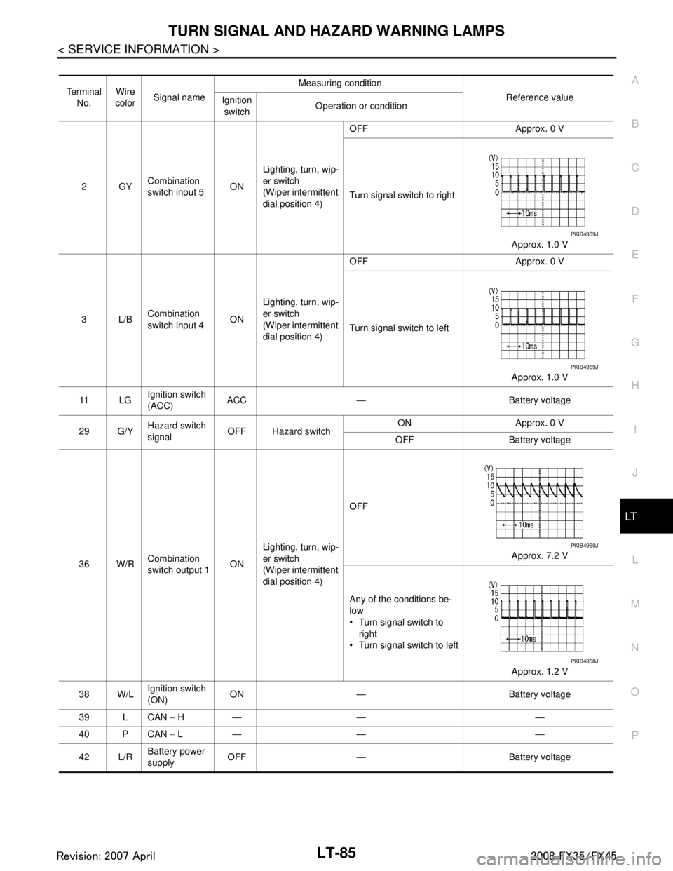
2GY Combination
switch input 5
ONLighting, turn, wip-
er switch
(Wiper intermittent
dial position 4) OFF Approx. 0 V
Turn signal switch to right
Approx. 1.0 V
3L/B Combination
switch input 4 ONLighting, turn, wip-
er switch
(Wiper intermittent
dial position 4) OFF Approx. 0 V
Turn signal switch to left
Approx. 1.0 V
11 L G Ignition switch
(ACC) ACC — Battery voltage
29 G/Y Hazard switch
signal OFF Hazard switch ON Approx. 0 V
OFF Battery voltage
36 W/R Combination
switch output 1 ONLighting, turn, wip-
er switch
(Wiper intermittent
dial position 4) OFF
Approx. 7.2 V
Any of the conditions be-
low
Turn signal switch to right
Turn signal switch to left
Approx. 1.2 V
38 W/L Ignition switch
(ON)
ON — Battery voltage
39 L CAN − H— — —
40 P CAN − L— — —
42 L/R Battery power
supply
OFF — Battery voltage
PKIB4959J
PKIB4959J
PKIB4960J
PKIB4958J
3AA93ABC3ACD3AC03ACA3AC03AC63AC53A913A773A893A873A873A8E3A773A983AC73AC93AC03AC3
3A893A873A873A8F3A773A9D3AAF3A8A3A8C3A863A9D3AAF3A8B3A8C
Page 3188 of 3924

LT-86
< SERVICE INFORMATION >
TURN SIGNAL AND HAZARD WARNING LAMPS
Terminal and Reference Value for Re ar Combination Lamp Control Unit
INFOID:0000000001328350
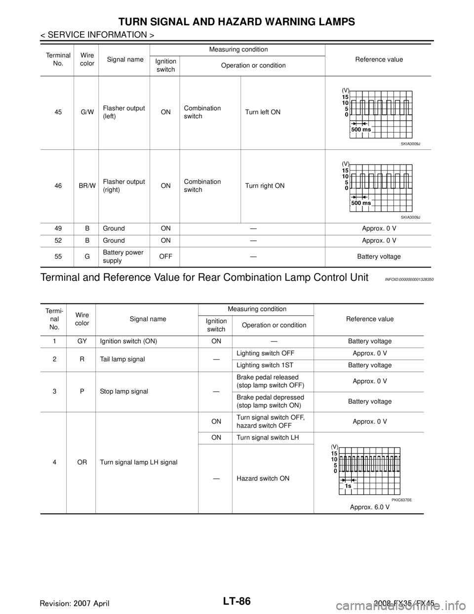
45 G/WFlasher output
(left) ON
Combination
switch Turn left ON
46 BR/W Flasher output
(right) ONCombination
switch Turn right ON
49 B Ground ON — Approx. 0 V
52 B Ground ON — Approx. 0 V
55 G Battery power
supply OFF — Battery voltage
Te r m i n a l
No. Wire
color Signal name Measuring condition
Reference value
Ignition
switch Operation or condition
SKIA3009J
SKIA3009J
Te r m i -
nal
No. Wire
color Signal name Measuring condition
Reference value
Ignition
switch Operation or condition
1 GY Ignition switch (ON) ON — Battery voltage
2 R Tail lamp signal — Lighting switch OFF Approx. 0 V
Lighting switch 1ST Battery voltage
3 P Stop lamp signal — Brake pedal released
(stop lamp switch OFF)
Approx. 0 V
Brake pedal depressed
(stop lamp switch ON) Battery voltage
4 OR Turn signal lamp LH signal ON
Turn signal switch OFF,
hazard switch OFF
Approx. 0 V
ON Turn signal switch LH
Approx. 6.0 V
— Hazard switch ON
PKIC6370E
3AA93ABC3ACD3AC03ACA3AC03AC63AC53A913A773A893A873A873A8E3A773A983AC73AC93AC03AC3
3A893A873A873A8F3A773A9D3AAF3A8A3A8C3A863A9D3AAF3A8B3A8C
Page 3189 of 3924

TURN SIGNAL AND HAZARD WARNING LAMPSLT-87
< SERVICE INFORMATION >
C
DE
F
G H
I
J
L
M A
B
LT
N
O P
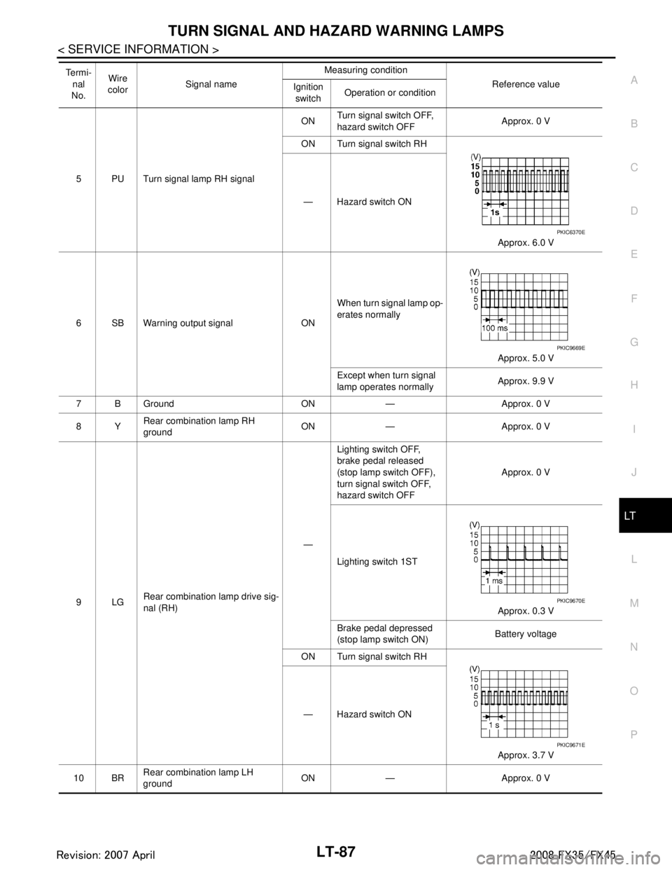
5 PU Turn signal lamp RH signal ON
Turn signal switch OFF,
hazard switch OFF
Approx. 0 V
ON Turn signal switch RH
Approx. 6.0 V
— Hazard switch ON
6 SB Warning output signal ON When turn signal lamp op-
erates normally
Approx. 5.0 V
Except when turn signal
lamp operates normally Approx. 9.9 V
7 B Ground ON — Approx. 0 V
8Y Rear combination lamp RH
ground ON — Approx. 0 V
9LG Rear combination lamp drive sig-
nal (RH) —Lighting switch OFF,
brake pedal released
(stop lamp switch OFF),
turn signal switch OFF,
hazard switch OFF
Approx. 0 V
Lighting switch 1ST Approx. 0.3 V
Brake pedal depressed
(stop lamp switch ON) Battery voltage
ON Turn signal switch RH
Approx. 3.7 V
— Hazard switch ON
10 BR Rear combination lamp LH
ground
ON — Approx. 0 V
Te r m i -
nal
No. Wire
color Signal name Measuring condition
Reference value
Ignition
switch Operation or condition
PKIC6370E
PKIC9669E
PKIC9670E
PKIC9671E
3AA93ABC3ACD3AC03ACA3AC03AC63AC53A913A773A893A873A873A8E3A773A983AC73AC93AC03AC3
3A893A873A873A8F3A773A9D3AAF3A8A3A8C3A863A9D3AAF3A8B3A8C