Page 3150 of 3924

LT-48
< SERVICE INFORMATION >
AUTO LIGHT SYSTEM
The headlamps will then illuminate. For a description of headlamp operation, Refer to LT- 5 , "System Descrip-
tion".
COMBINATION SWITCH READING FUNCTION
Refer to BCS-4, "System Description".
DELAY TIMER FUNCTION
Delay timer function carries out a function that BCM ac tivates the timer and controls lights out of headlamps by
door switch signal and lightning switch signal when turn ing the Ignition switch OFF while it is ON and head-
lamps are ON by the auto light function.
Timer types are a 5 minute timer and a 45 second timer
When opening any door (door switch is ON), the 5 mi nute timer starts and then headlamps go out 5 minutes
later
When all the doors are closed (from door switch ON to OFF), the 45 second timer starts and then headlamps go out 45 seconds later. If any door is opened (door switch ON) while the 45 second timer is in operation, the
5 minute timer starts again
The timer stops when turning on the ignition switch or turning off the auto light switch under the above condi-
tions.
Delay timer control mode can be changed by the f unction setting of CONSULT-III or display.
CAN Communication System DescriptionINFOID:0000000001328308
CAN (Controller Area Network) is a serial communication line for real time application. It is an on-vehicle mul-
tiplex communication line with high data communication s peed and excellent error detection ability. Many elec-
tronic control units are equipped onto a vehicle, and each control unit shares information and links with other
control units during operation (not independent). In CA N communication, control units are connected with 2
communication lines (CAN H line, CAN L line) allowing a high rate of information transmission with less wiring.
Each control unit transmits/receives data but selectively reads required data only.
CAN Communication UnitINFOID:0000000001328309
Refer to LAN-43, "CAN System Specification Chart".
Major Component and FunctionsINFOID:0000000001328310
Components Functions
BCM Turns on/off circuits of tail light and headlamp according to signals from light sensor, lighting switch (AUTO),
driver door switch, passenger door switch, rear door switch, and ignition switch (ON, OFF).
Optical sensor Converts outside brightness (lux) to voltage, and sends it to BCM. (Detects brightness of 800 to 2,500 lux)
3AA93ABC3ACD3AC03ACA3AC03AC63AC53A913A773A893A873A873A8E3A773A983AC73AC93AC03AC3
3A893A873A873A8F3A773A9D3AAF3A8A3A8C3A863A9D3AAF3A8B3A8C
Page 3151 of 3924
AUTO LIGHT SYSTEMLT-49
< SERVICE INFORMATION >
C
DE
F
G H
I
J
L
M A
B
LT
N
O P
SchematicINFOID:0000000001328311
TKWM0611E
3AA93ABC3ACD3AC03ACA3AC03AC63AC53A913A773A893A873A873A8E3A773A983AC73AC93AC03AC3
3A893A873A873A8F3A773A9D3AAF3A8A3A8C3A863A9D3AAF3A8B3A8C
Page 3152 of 3924
LT-50
< SERVICE INFORMATION >
AUTO LIGHT SYSTEM
Wiring Diagram - AUTO/L -
INFOID:0000000001328312
TKWM4297E
3AA93ABC3ACD3AC03ACA3AC03AC63AC53A913A773A893A873A873A8E3A773A983AC73AC93AC03AC3
3A893A873A873A8F3A773A9D3AAF3A8A3A8C3A863A9D3AAF3A8B3A8C
Page 3153 of 3924
AUTO LIGHT SYSTEMLT-51
< SERVICE INFORMATION >
C
DE
F
G H
I
J
L
M A
B
LT
N
O P
TKWM4298E
3AA93ABC3ACD3AC03ACA3AC03AC63AC53A913A773A893A873A873A8E3A773A983AC73AC93AC03AC3
3A893A873A873A8F3A773A9D3AAF3A8A3A8C3A863A9D3AAF3A8B3A8C
Page 3154 of 3924
LT-52
< SERVICE INFORMATION >
AUTO LIGHT SYSTEM
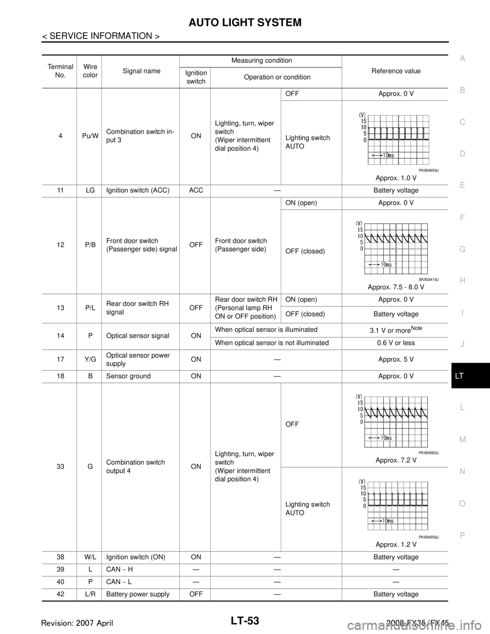
Terminal and Reference Value for BCM
INFOID:0000000001328313
CAUTION:
Check combination switch system terminal waveform under the loaded condition with lighting
switch, turn signal switch and wiper switch OFF not to be fluctuated by overloaded.
Turn wiper intermittent dial posi tion to 4 except when checking wavef orm or voltage of wiper inter-
mittent dial position. Wiper intermittent dial position can be confirmed on CONSULT-III. Refer to LT-
103, "CONSULT-III Functions (BCM)".
TKWM4299E
3AA93ABC3ACD3AC03ACA3AC03AC63AC53A913A773A893A873A873A8E3A773A983AC73AC93AC03AC3
3A893A873A873A8F3A773A9D3AAF3A8A3A8C3A863A9D3AAF3A8B3A8C
Page 3155 of 3924

AUTO LIGHT SYSTEMLT-53
< SERVICE INFORMATION >
C
DE
F
G H
I
J
L
M A
B
LT
N
O P
Te r m i n a l No. Wire
color Signal name Measuring condition
Reference value
Ignition
switch Operation or condition
4Pu/W Combination switch in-
put 3
ONLighting, turn, wiper
switch
(Wiper intermittent
dial position 4) OFF Approx. 0 V
Lighting switch
AUTO
Approx. 1.0 V
11 LG Ignition switch (ACC) ACC — Battery voltage
12 P/B Front door switch
(Passenger side) signal OFFFront door switch
(Passenger side) ON (open) Approx. 0 V
OFF (closed)
Approx. 7.5 - 8.0 V
13 P/L Rear door switch RH
signal OFFRear door switch RH
(Personal lamp RH
ON or OFF position) ON (open) Approx. 0 V
OFF (closed) Battery voltage
14 P Optical sensor signal ON When optical sensor is illuminated
3.1 V or more
Note
When optical sensor is not illuminated 0.6 V or less
17 Y/G Optical sensor power
supply ON — Approx. 5 V
18 B Sensor ground ON — Approx. 0 V
33 G Combination switch
output 4 ONLighting, turn, wiper
switch
(Wiper intermittent
dial position 4) OFF
Approx. 7.2 V
Lighting switch
AUTO Approx. 1.2 V
38 W/L Ignition switch (ON) ON — Battery voltage
39 L CAN − H— — —
40 P CAN − L— — —
42 L/R Battery power supply OFF — Battery voltage
PKIB4959J
SKIB3419J
PKIB4960J
PKIB4958J
3AA93ABC3ACD3AC03ACA3AC03AC63AC53A913A773A893A873A873A8E3A773A983AC73AC93AC03AC3
3A893A873A873A8F3A773A9D3AAF3A8A3A8C3A863A9D3AAF3A8B3A8C
Page 3156 of 3924

LT-54
< SERVICE INFORMATION >
AUTO LIGHT SYSTEM
NOTE:
Optical sensor must be securely subjected to work lamp light. If optical sensor is insufficiently illuminated, the measured value may not
satisfy standard.
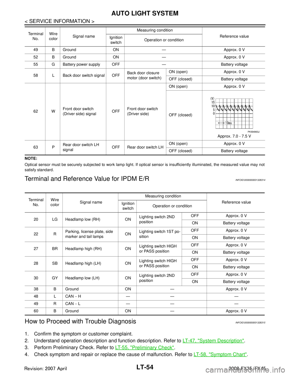
Terminal and Reference Value for IPDM E/RINFOID:0000000001328314
How to Proceed with Trouble DiagnosisINFOID:0000000001328315
1. Confirm the symptom or customer complaint.
2. Understand operation description and function description. Refer to LT-47, "
System Description".
3. Perform Preliminary Check. Refer to LT-55, "
Preliminary Check".
4. Check symptom and repair or replace the cause of malfunction. Refer to LT-58, "
Symptom Chart".
49 B Ground ON — Approx. 0 V
52 B Ground ON — Approx. 0 V
55 G Battery power supply OFF — Battery voltage
58 L Back door switch signal OFF Back door closure
motor (door switch)ON (open) Approx. 0 V
OFF (closed) Battery voltage
62 W Front door switch
(Driver side) signal OFFFront door switch
(Driver side) ON (open) Approx. 0 V
OFF (closed)
Approx. 7.0 - 7.5 V
63 P Rear door switch LH
signal OFF Rear door switch LH ON (open) Approx. 0 V
OFF (closed) Battery voltage
Te r m i n a l
No. Wire
color Signal name Measuring condition
Reference value
Ignition
switch Operation or condition
PKIB4960J
Te r m i n a l
No. Wire
color Signal name Measuring condition
Reference value
Ignition
switch Operation or condition
20 LG Headlamp low (RH) ON Lighting switch 2ND
positionOFF Approx. 0 V
ON Battery voltage
22 R Parking, license plate, side
marker and tail lamps ON
Lighting switch 1ST po-
sition OFF Approx. 0 V
ON Battery voltage
27 BR Headlamp high (RH) ON Lighting switch HIGH
or PASS positionOFF Approx. 0 V
ON Battery voltage
28 SB Headlamp high (LH) ON Lighting switch HIGH
or PASS positionOFF Approx. 0 V
ON Battery voltage
30 GY Headlamp low (LH) ON Lighting switch 2ND
positionOFF Approx. 0 V
ON Battery voltage
38 B Ground ON — Approx. 0 V
48 L CAN − H—— —
49 R CAN − L—— —
60 B Ground ON — Approx. 0 V
3AA93ABC3ACD3AC03ACA3AC03AC63AC53A913A773A893A873A873A8E3A773A983AC73AC93AC03AC3
3A893A873A873A8F3A773A9D3AAF3A8A3A8C3A863A9D3AAF3A8B3A8C
Page 3157 of 3924

AUTO LIGHT SYSTEMLT-55
< SERVICE INFORMATION >
C
DE
F
G H
I
J
L
M A
B
LT
N
O P
5. Does auto light system operate normally? If YES, GO TO 6. If NO, GO TO 4.
6. INSPECTION END
Preliminary CheckINFOID:0000000001328316
SETTING CHANGE FUNCTIONS
Sensitivity of auto light system can be adjusted using CONSULT-III. Refer to LT-56, "CONSULT-III Functions
(BCM)".
CHECK POWER SUPPLY AND GROUND CIRCUIT
1.CHECK FUSES
Check for blown fuses.
Refer to LT- 5 0 , "Wiring Diagram - AUTO/L -".
OK or NG
OK >> GO TO 2.
NG >> If fuse is blown, be sure to eliminate caus e of malfunction before installing new fuse. Refer to PG-
3.
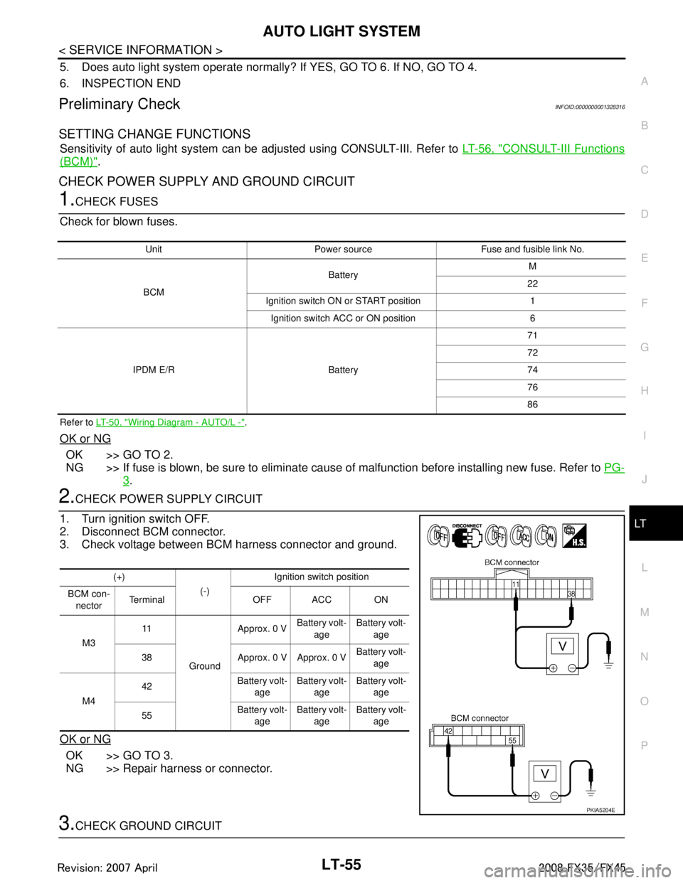
2.CHECK POWER SUPPLY CIRCUIT
1. Turn ignition switch OFF.
2. Disconnect BCM connector.
3. Check voltage between BCM harness connector and ground.
OK or NG
OK >> GO TO 3.
NG >> Repair harness or connector.
3.CHECK GROUND CIRCUIT
Unit Power source Fuse and fusible link No.
BCM Battery
M
22
Ignition switch ON or START position 1 Ignition switch ACC or ON position 6
IPDM E/R Battery 71
72
74
76
86
(+)
(-)Ignition switch position
BCM con- nector Te r m i n a l O F F A C C O N
M3 11
Ground Approx. 0 V
Battery volt-
age Battery volt-
age
38 Approx. 0 V Approx. 0 V Battery volt-
age
M4 42
Battery volt-
age Battery volt-
age Battery volt-
age
55 Battery volt-
age Battery volt-
age Battery volt-
age
PKIA5204E
3AA93ABC3ACD3AC03ACA3AC03AC63AC53A913A773A893A873A873A8E3A773A983AC73AC93AC03AC3
3A893A873A873A8F3A773A9D3AAF3A8A3A8C3A863A9D3AAF3A8B3A8C