Page 3206 of 3924

LT-104
< SERVICE INFORMATION >
COMBINATION SWITCH
CONSULT-III BASIC OPERATION
Refer to GI-34, "Description".
DATA MONITOR
Display Item List
NOTE:
This item is displayed, but cannot be monitored
Combination Switch InspectionINFOID:0000000001381755
1.SYSTEM CHECK
Referring to table below, check which sy stem malfunctioning switch belongs to.
>> Check the system to which malfunctioning switch belongs, and then GO TO 2.
2.SYSTEM CHECK
CONSULT-III DATA MONITOR
1. Select “COMBI SW” of BCM data monitor item.
2. Confirm that other switches in malfunctioning system operate normally.
Monitor item Contents
TURN SIGNAL R “ON/OFF” Displays “Turn Ri ght (ON)/Other (OFF)” status, determined from lighting switch signal.
TURN SIGNAL L “ON/OFF” Displays “Turn Le ft (ON)/Other (OFF)” status, determined from lighting switch signal.
HI BEAM SW “ON/OFF” Displays status (high beam switch: ON/Others: OFF) of high beam switch judged from lighting switch
signal.
HEAD LAMP SW 1 “ON/OFF” Displays status (headlamp switch 2: ON/Others:
OFF) of headlamp switch 1 judged from lighting
switch signal.
HEAD LAMP SW 2 “ON/OFF” Displays status (headlamp switch 2: ON/Others:
OFF) of headlamp switch 2 judged from lighting
switch signal.
LIGHT SW 1ST “ON/OFF” Displays status (lighting switch 1ST or 2ND position: ON/Others: OFF) of lighting switch judged from
lighting switch signal.
PASSING SW “ON/OFF” Displays status (flash-to-pass switch: ON/Others: OFF) of flash-to-pass switch judged from lighting
switch signal.
AUTO LIGHT SW “ON/OFF” Displays “Auto light switch (ON)/Other (OFF)” status, determined from lighting switch signal.
FR FOG SW “ON/OFF” Displays “Fro nt fog lamp switch (ON)/Other (OFF)” status, determined from lighting switch signal.
RR FOG SW
NOTE“OFF” —
FR WIPER HI “ON/OFF” Disp lays “Front Wiper HI (ON)/Other (OFF)” stat us, determined from wiper switch signal.
FR WIPER LOW “ON/OFF” Displays “Front Wiper LOW (ON)/Oth er (OFF)” status, determined from wiper switch signal.
FR WIPER INT “ON/OFF” Displays “Front Wiper INT (ON)/Other (OFF)” status, determined from wiper switch signal.
FR WASHER SW “ON/OFF” Displays “Front Washer Switch (ON)/Other (OFF)” status, determined from wiper switch signal.
INT VOLUME “1 – 7” Displays intermittent operation knob setting (1 – 7), determined from wiper switch signal.
RR WIPER ON “ON/OFF” Displays “rear Wiper (ON)/Other (OFF)” status as judged from wiper switch signal.
RR WIPER INT “ON/OFF” Displays “rear Wiper INT (ON)/Other (OFF)” status as judged from wiper switch signal.
RR WASHER SW “ON/OFF” Displays “rear Washer Switch (ON)/Other (OFF)” status as judged from wiper switch signal.
System 1 System 2 System 3 System 4 System 5 — FR WASHER FR WIPER LO TURN LH TURN RH
FR WIPER HI — FR WIPER INT PASSING HEAD LAMP 1
INT VOLUME 1 RR WASHER — HEAD LAMP HI BEAM RR WIPER INT INT VOLUME 3 AUTO LIGHT — LIGHT SW 1
INT VOLUME 2 RR WIPER ON — FR FOG —
3AA93ABC3ACD3AC03ACA3AC03AC63AC53A913A773A893A873A873A8E3A773A983AC73AC93AC03AC3
3A893A873A873A8F3A773A9D3AAF3A8A3A8C3A863A9D3AAF3A8B3A8C
Page 3207 of 3924

COMBINATION SWITCHLT-105
< SERVICE INFORMATION >
C
DE
F
G H
I
J
L
M A
B
LT
N
O P
Example: When the HI BEAM switch is malfuncti oning, confirm that “TURN RH”, “HEAD LAMP 1” and
“LIGHT SW 1 ST” in System 5, to which the HI BEAM switch belongs, turn ON-OFF normally.
Without CONSULT-III
Operating combination switch, and confirm that other switches in malfunctioning system operate normally.
Example: When the HI BEAM switch is malfunctioni ng, confirm that “TURN RH”, “HEAD LAMP 1” and “LIGHT
SW 1 ST” in System 5, to which HI BE AM switch belongs, turn ON-OFF normally.
Check results
Other switches in malfunctioning system operate normally.>>Replace light ing switch or wiper switch.
Other switches in malfunctioning syst em do not operate normally.>>GO TO 3.
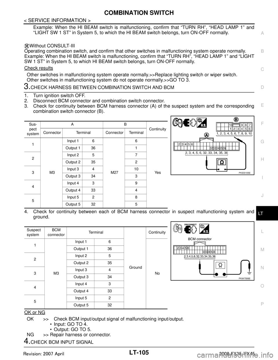
3.CHECK HARNESS BETWEEN COMB INATION SWITCH AND BCM
1. Turn ignition switch OFF.
2. Disconnect BCM connector and combination switch connector.
3. Check for continuity between BCM harness connecto r (A) of the suspect system and the corresponding
combination switch connector (B).
4. Check for continuity between each of BCM harne ss connector in suspect malfunctioning system and
ground.
OK or NG
OK >> Check BCM input/output signal of malfunctioning input/output.
Input: GO TO 4.
Output: GO TO 5.
NG >> Repair harness or connector.
4.CHECK BCM INPUT SIGNAL
Sus-
pect
system AB
Continuity
Connector Terminal Connector Terminal
1
M3 Input 1 6
M276
Ye s
Output 1 36 1
2 Input 2 5 7
Output 2 35 2
3 Input 3 4 10
Output 3 34 3
4 Input 4 3 9
Output 4 33 4
5 Input 5 2 8
Output 5 32 5
Suspect
system BCM
connector Te r m i n a l
GroundContinuity
1
M3 Input 1 6
No
Output 1 36
2 Input 2 5
Output 2 35
3 Input 3 4
Output 3 34
4 Input 4 3
Output 4 33
5 Input 5 2
Output 5 32
PKID0105E
PKIA7506E
3AA93ABC3ACD3AC03ACA3AC03AC63AC53A913A773A893A873A873A8E3A773A983AC73AC93AC03AC3
3A893A873A873A8F3A773A9D3AAF3A8A3A8C3A863A9D3AAF3A8B3A8C
Page 3208 of 3924

LT-106
< SERVICE INFORMATION >
COMBINATION SWITCH
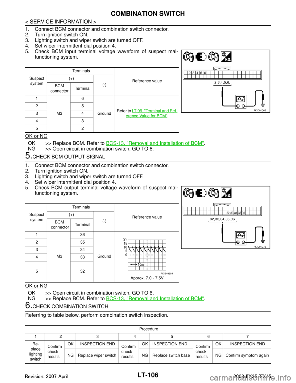
1. Connect BCM connector and combination switch connector.
2. Turn ignition switch ON.
3. Lighting switch and wiper switch are turned OFF.
4. Set wiper intermittent dial position 4.
5. Check BCM input terminal voltage waveform of suspect mal-functioning system.
OK or NG
OK >> Replace BCM. Refer to BCS-13, "Removal and Installation of BCM".
NG >> Open circuit in combination switch, GO TO 6.
5.CHECK BCM OUTPUT SIGNAL
1. Connect BCM connector and combination switch connector.
2. Turn ignition switch ON.
3. Lighting switch and wiper switch are turned OFF.
4. Set wiper intermittent dial position 4.
5. Check BCM output terminal voltage waveform of suspect mal- functioning system.
OK or NG
OK >> Open circuit in combination switch, GO TO 6.
NG >> Replace BCM. Refer to BCS-13, "
Removal and Installation of BCM".
6.CHECK COMBINATION SWITCH
Referring to table below, perform combination switch inspection.
Suspect system Te r m i n a l s
Reference value
(+)
(-)
BCM
connector Te r m i n a l
1
M3 6
Ground Refer to
LT- 9 9 , "
Terminal and Ref-
erence Value for BCM".
25
34
43
52
PKID0106E
Suspect
system Te r m i n a l s
Reference value
(+)
(-)
BCM
connector Te r m i n a l
1
M3 36
Ground Approx. 7.0 - 7.5V
235
334
433
532
PKID0107E
PKIB4960J
Procedure
12 3 4 5 6 7
Re-
place
lighting switch Confirm
check
results
OK INSPECTION END
Confirm
check
resultsOK INSPECTION END
Confirm
check
resultsOK INSPECTION END
NG Replace wiper switch NG Replace switch base NG Confirm symptom again
3AA93ABC3ACD3AC03ACA3AC03AC63AC53A913A773A893A873A873A8E3A773A983AC73AC93AC03AC3
3A893A873A873A8F3A773A9D3AAF3A8A3A8C3A863A9D3AAF3A8B3A8C
Page 3209 of 3924
COMBINATION SWITCHLT-107
< SERVICE INFORMATION >
C
DE
F
G H
I
J
L
M A
B
LT
N
O P
>> INSPECTION END
Removal and InstallationINFOID:0000000001328369
Refer to LT- 9 6 and WW-28, "Removal and Installation of Front Wiper and Washer Switch".
3AA93ABC3ACD3AC03ACA3AC03AC63AC53A913A773A893A873A873A8E3A773A983AC73AC93AC03AC3
3A893A873A873A8F3A773A9D3AAF3A8A3A8C3A863A9D3AAF3A8B3A8C
Page 3210 of 3924
LT-108
< SERVICE INFORMATION >
STOP LAMP
STOP LAMP
Component Parts and Harness Connector LocationINFOID:0000000001328370
System DescriptionINFOID:0000000001328371
The current that flows by Rear combination lamp cont rol unit is controlled, and a stop lamp (LED) is made to
turn on.
PKIC9693E
3AA93ABC3ACD3AC03ACA3AC03AC63AC53A913A773A893A873A873A8E3A773A983AC73AC93AC03AC3
3A893A873A873A8F3A773A9D3AAF3A8A3A8C3A863A9D3AAF3A8B3A8C
Page 3211 of 3924
STOP LAMPLT-109
< SERVICE INFORMATION >
C
DE
F
G H
I
J
L
M A
B
LT
N
O P
SchematicINFOID:0000000001328372
TKWM0625E
3AA93ABC3ACD3AC03ACA3AC03AC63AC53A913A773A893A873A873A8E3A773A983AC73AC93AC03AC3
3A893A873A873A8F3A773A9D3AAF3A8A3A8C3A863A9D3AAF3A8B3A8C
Page 3212 of 3924
LT-110
< SERVICE INFORMATION >
STOP LAMP
Wiring Diagram - STOP/L -
INFOID:0000000001328373
TKWM4310E
3AA93ABC3ACD3AC03ACA3AC03AC63AC53A913A773A893A873A873A8E3A773A983AC73AC93AC03AC3
3A893A873A873A8F3A773A9D3AAF3A8A3A8C3A863A9D3AAF3A8B3A8C
Page 3213 of 3924
STOP LAMPLT-111
< SERVICE INFORMATION >
C
DE
F
G H
I
J
L
M A
B
LT
N
O P
TKWM4311E
3AA93ABC3ACD3AC03ACA3AC03AC63AC53A913A773A893A873A873A8E3A773A983AC73AC93AC03AC3
3A893A873A873A8F3A773A9D3AAF3A8A3A8C3A863A9D3AAF3A8B3A8C