2008 INFINITI FX35 light
[x] Cancel search: lightPage 2966 of 3924
![INFINITI FX35 2008 Service Manual
FRONT DOOR GLASS AND REGULATORGW-53
< SERVICE INFORMATION >
C
DE
F
G H
J
K L
M A
B
GW
N
O P
Lower the glass slightly [approx. 10 to 20 mm (0.39 to 0.79 in)] and make sure the clearance to the sash INFINITI FX35 2008 Service Manual
FRONT DOOR GLASS AND REGULATORGW-53
< SERVICE INFORMATION >
C
DE
F
G H
J
K L
M A
B
GW
N
O P
Lower the glass slightly [approx. 10 to 20 mm (0.39 to 0.79 in)] and make sure the clearance to the sash](/manual-img/42/57017/w960_57017-2965.png)
FRONT DOOR GLASS AND REGULATORGW-53
< SERVICE INFORMATION >
C
DE
F
G H
J
K L
M A
B
GW
N
O P
Lower the glass slightly [approx. 10 to 20 mm (0.39 to 0.79 in)] and make sure the clearance to the sash is parallel. If the clearance between the glass and sash is not parallel, loosen the regulator mounting bolts,
guide rail mounting bolts, and glass and guide rail mounting bolts to correct the glass position.
3AA93ABC3ACD3AC03ACA3AC03AC63AC53A913A773A893A873A873A8E3A773A983AC73AC93AC03AC3
3A893A873A873A8F3A773A9D3AAF3A8A3A8C3A863A9D3AAF3A8B3A8C
Page 2969 of 3924
GW-56
< SERVICE INFORMATION >
REAR DOOR GLASS AND REGULATOR
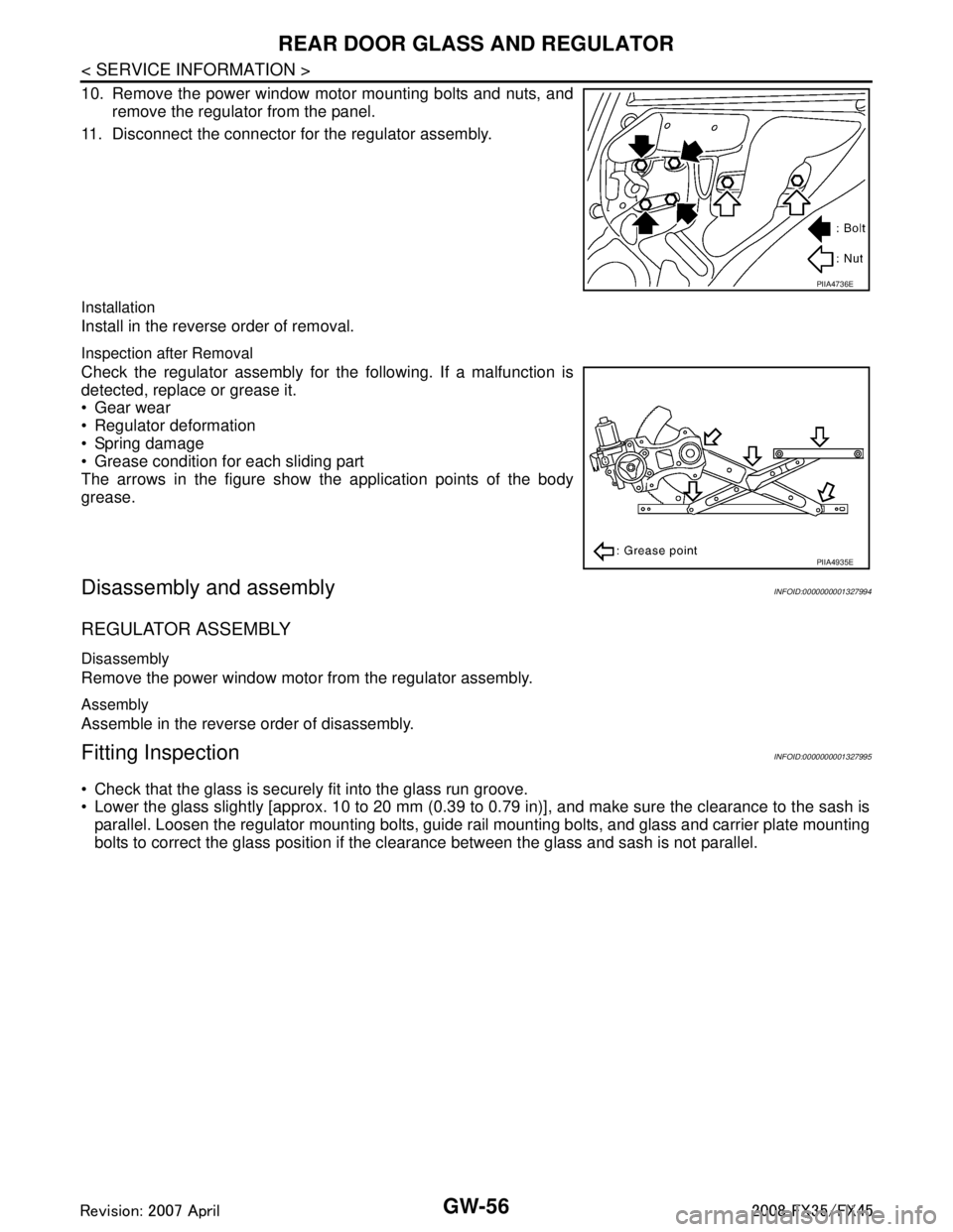
10. Remove the power window motor mounting bolts and nuts, andremove the regulator from the panel.
11. Disconnect the connector for the regulator assembly.
Installation
Install in the reverse order of removal.
Inspection after Removal
Check the regulator assembly for the following. If a malfunction is
detected, replace or grease it.
Gear wear
Regulator deformation
Spring damage
Grease condition for each sliding part
The arrows in the figure show the application points of the body
grease.
Disassembly and assemblyINFOID:0000000001327994
REGULATOR ASSEMBLY
Disassembly
Remove the power window motor from the regulator assembly.
Assembly
Assemble in the reverse order of disassembly.
Fitting InspectionINFOID:0000000001327995
Check that the glass is securely fit into the glass run groove.
Lower the glass slightly [approx. 10 to 20 mm (0.39 to 0.79 in)], and make sure the clearance to the sash is
parallel. Loosen the regulator mounting bolts, guide rail mounting bolts, and glass and carrier plate mounting
bolts to correct the glass position if the clearance between the glass and sash is not parallel.
PIIA4736E
PIIA4935E
3AA93ABC3ACD3AC03ACA3AC03AC63AC53A913A773A893A873A873A8E3A773A983AC73AC93AC03AC3
3A893A873A873A8F3A773A9D3AAF3A8A3A8C3A863A9D3AAF3A8B3A8C
Page 2981 of 3924
GW-68
< SERVICE INFORMATION >
REAR WINDOW DEFOGGER
CONSULT-III Function (IPDM E/R)
INFOID:0000000001328007
DATA MONITOR
ACTIVE TEST
Work FlowINFOID:0000000001328008
1. Check the symptom and customer's requests.
2. Understand the outline of system. Refer to GW-60, "
System Description".
3. According to the trouble diagnosis chart, repair or replace the cause of the malfunction. Refer to GW-68,
"Trouble Diagnosis Symptom Chart".
4. Does rear window defogger operate no rmally? YES: GO TO 5, NO: GO TO 3.
5. INSPECTION END.
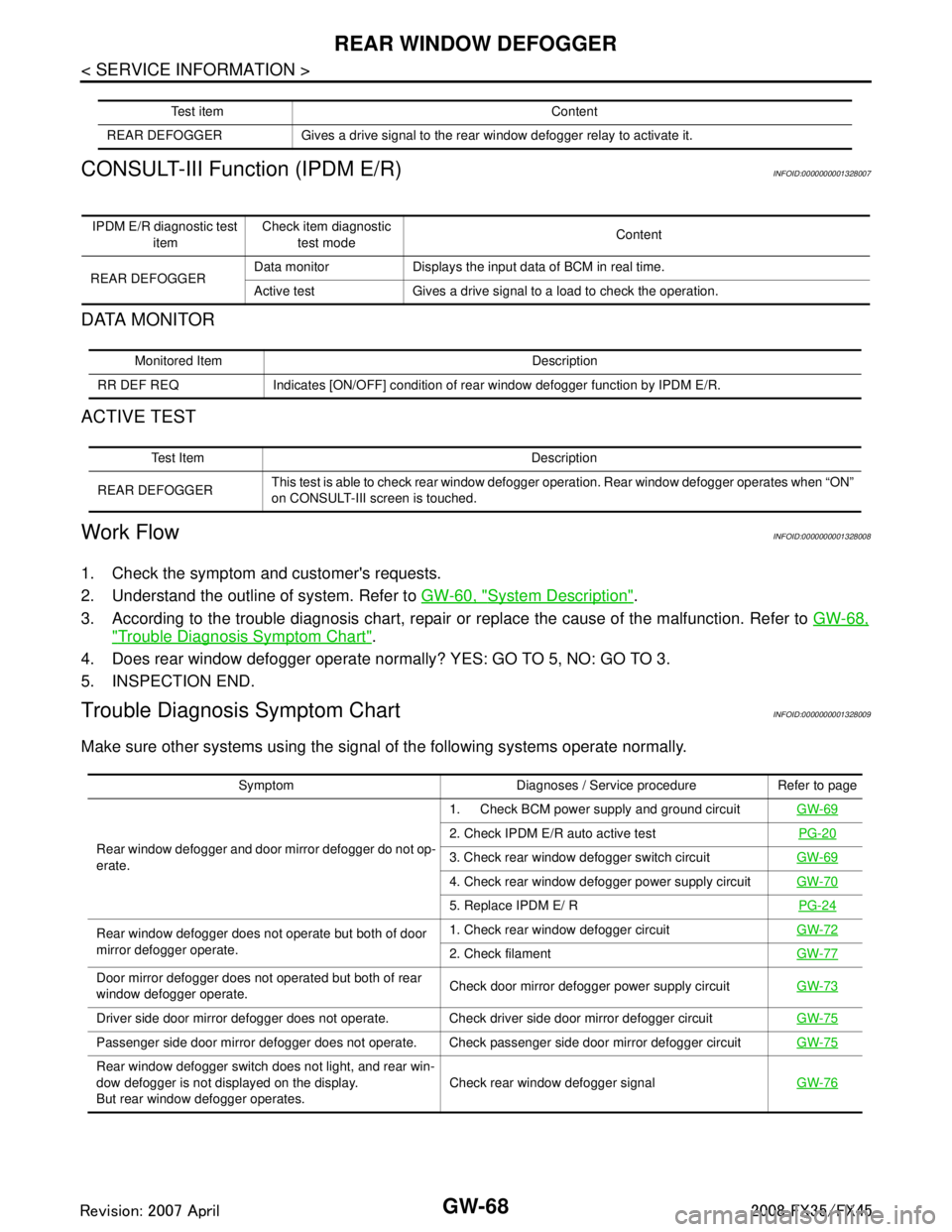
Trouble Diagnosis Symptom ChartINFOID:0000000001328009
Make sure other systems us ing the signal of the following systems operate normally.
Test item Content
REAR DEFOGGER Gives a drive sign al to the rear window defogger rela y to activate it.
IPDM E/R diagnostic test
item Check item diagnostic
test mode Content
REAR DEFOGGER Data monitor Displays the input data of BCM in real time.
Active test Gives a drive signal to a load to check the operation.
Monitored Item Description
RR DEF REQ Indicates [ON/OFF] condition of rear window defogger function by IPDM E/R.
Test Item Description
REAR DEFOGGER This test is able to check rear window defogger operation. Rear window defogger operates when “ON”
on CONSULT-III screen is touched.
Symptom Diagnoses / Service procedure Refer to page
Rear window defogger and door mirror defogger do not op-
erate. 1. Check BCM power supply and ground circuit
GW-69
2. Check IPDM E/R auto active test PG-20
3. Check rear window defogger switch circuit GW-69
4. Check rear window defogger power supply circuit GW-70
5. Replace IPDM E/ R PG-24
Rear window defogger does not operate but both of door
mirror defogger operate. 1. Check rear window defogger circuit
GW-72
2. Check filament GW-77
Door mirror defogger does not operated but both of rear
window defogger operate. Check door mirror defogger power supply circuit
GW-73
Driver side door mirror defogger does not operate. Check driver side door mirror defogger circuit GW-75
Passenger side door mirror defogger does not operate. Check passenger side door mirror defogger circuit GW-75
Rear window defogger switch does not light, and rear win-
dow defogger is not displayed on the display.
But rear window defogger operates. Check rear window defogger signal
GW-76
3AA93ABC3ACD3AC03ACA3AC03AC63AC53A913A773A893A873A873A8E3A773A983AC73AC93AC03AC3
3A893A873A873A8F3A773A9D3AAF3A8A3A8C3A863A9D3AAF3A8B3A8C
Page 2989 of 3924

GW-76
< SERVICE INFORMATION >
REAR WINDOW DEFOGGER
4. Check voltage between door mirror (passenger side) connectorand ground.
OK or NG
OK >> GO TO 2.
NG >> Repair or replace harness.
2.CHECK GROUND CIRCUIT
1. Turn ignition switch OFF.
2. Check continuity between door mirror (passenger side) connec- tor and ground.
OK or NG
OK >> GO TO 3.
NG >> Repair or replace harness.
3.CHECK DOOR MIRROR DEFOGGER
1. Connector door mirror connector.
2. Check continuity between each door mirror connector.
OK or NG
OK >> Check condition of harness and connector.
NG >> Replace door mirror (passenger side).
Check Rear Windo w Defogger SignalINFOID:0000000001328017
1.CHECK REAR WINDOW DEFOGGER SWITCH LAMP
A/C and AV switch self-diagnosis is performed. Refer to AV-34, "
A/C and AV Switch Self-Diagnosis Function"
Does rear window defogger switch light?
YES >> GO TO 2.
NO >> Replace A/C and AV switch.
2.CHECK AV COMMUNICATION LINE
AV communication line check is performed. Refer to AV-79, "
Unable to Operate System with A/C and AV
Switch"
Is rear window defogger displayed on the display?
YES >> GO TO 3.
NO >> Replace display control unit.
3.CHECK CAN COMMUNICATION LINE
ConnectorTerminal (Wire color)
ConditionVoltage (V)
(Approx.)
(+) (–)
D32 4 (L) Ground Rear window defogger
switch ON
Battery voltage
Rear window defogger
switch OFF 0
PIIB8572E
Door mirror
connector terminal
GroundContinuity
D2 (driver side)
D32 (passenger side) 3(B) Yes
PIIB8570E
Door mirror
connector terminal Terminal Continuity
D2 (driver side)
D32 (passenger side) 3(B) 4(L) Yes
PIIB8571E
3AA93ABC3ACD3AC03ACA3AC03AC63AC53A913A773A893A873A873A8E3A773A983AC73AC93AC03AC3
3A893A873A873A8F3A773A9D3AAF3A8A3A8C3A863A9D3AAF3A8B3A8C
Page 2991 of 3924
GW-78
< SERVICE INFORMATION >
REAR WINDOW DEFOGGER
Conductive silver composition (Dupont No. 4817 or equivalent)
Ruler 30 cm (11.8 in) long
Drawing pen
Heat gun
Alcohol
Cloth
REPAIRING PROCEDURE
1. Wipe broken heat wire and its surrounding area clean with acloth dampened in alcohol.
2. Apply a small amount of conductive silver composition to tip of
drawing pen.
Shake silver composition container before use.
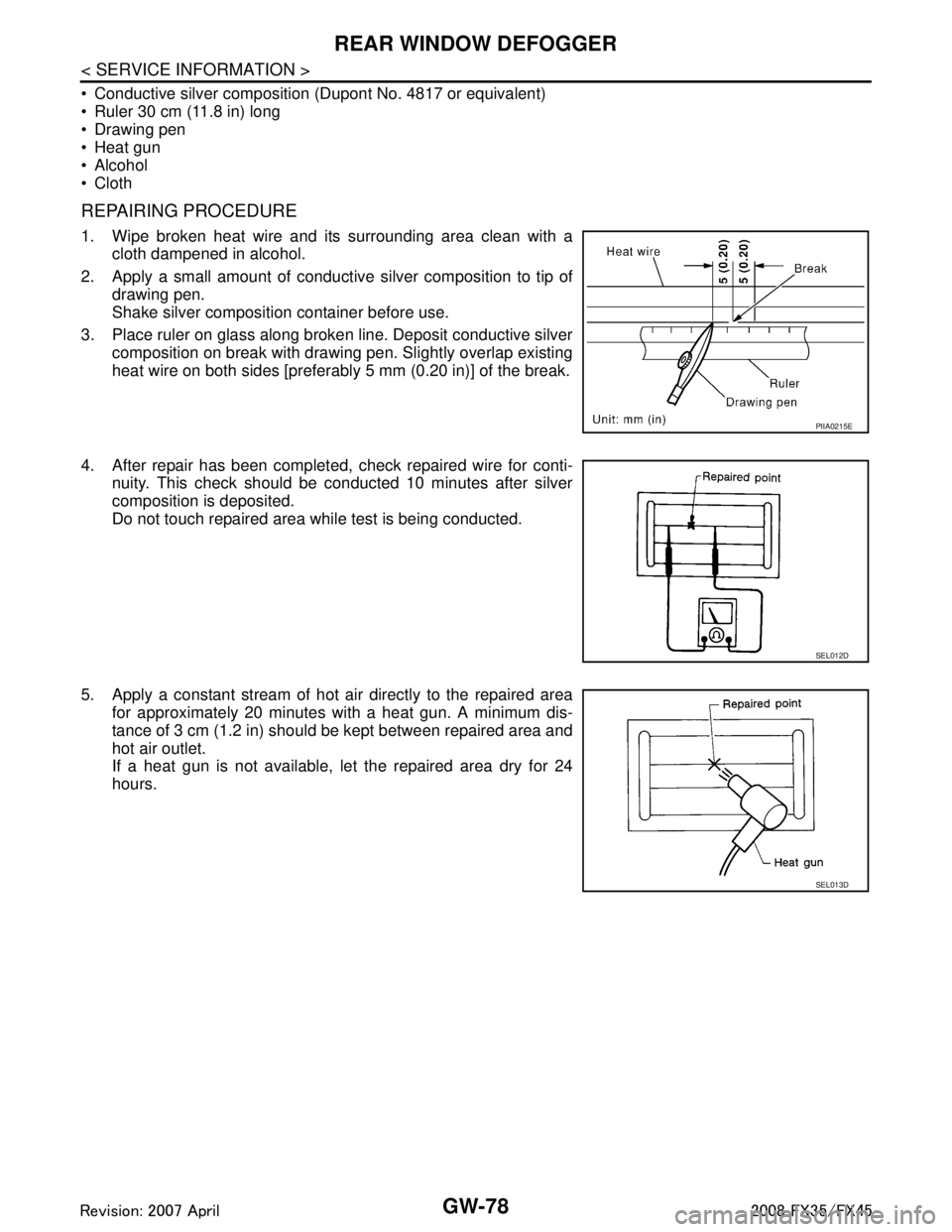
3. Place ruler on glass along broken line. Deposit conductive silver composition on break with drawing pen. Slightly overlap existing
heat wire on both sides [preferably 5 mm (0.20 in)] of the break.
4. After repair has been completed, check repaired wire for conti- nuity. This check should be conducted 10 minutes after silver
composition is deposited.
Do not touch repaired area while test is being conducted.
5. Apply a constant stream of hot air directly to the repaired area for approximately 20 minutes with a heat gun. A minimum dis-
tance of 3 cm (1.2 in) should be kept between repaired area and
hot air outlet.
If a heat gun is not available, let the repaired area dry for 24
hours.
PIIA0215E
SEL012D
SEL013D
3AA93ABC3ACD3AC03ACA3AC03AC63AC53A913A773A893A873A873A8E3A773A983AC73AC93AC03AC3
3A893A873A873A8F3A773A9D3AAF3A8A3A8C3A863A9D3AAF3A8B3A8C
Page 3001 of 3924
GW-88
< SERVICE INFORMATION >
DOOR MIRROR
5. Lightly lift up lower side of mirror surface, and detach pawls of upper side from bracket as if pulling it out.
Remove mirror surface from mirror body.
NOTE:
Be certain not to allow grease on sealing agent in cent er of mirror body assembly (actuator) or back side of
mirror surface (mirror holder).
ASSEMBLY
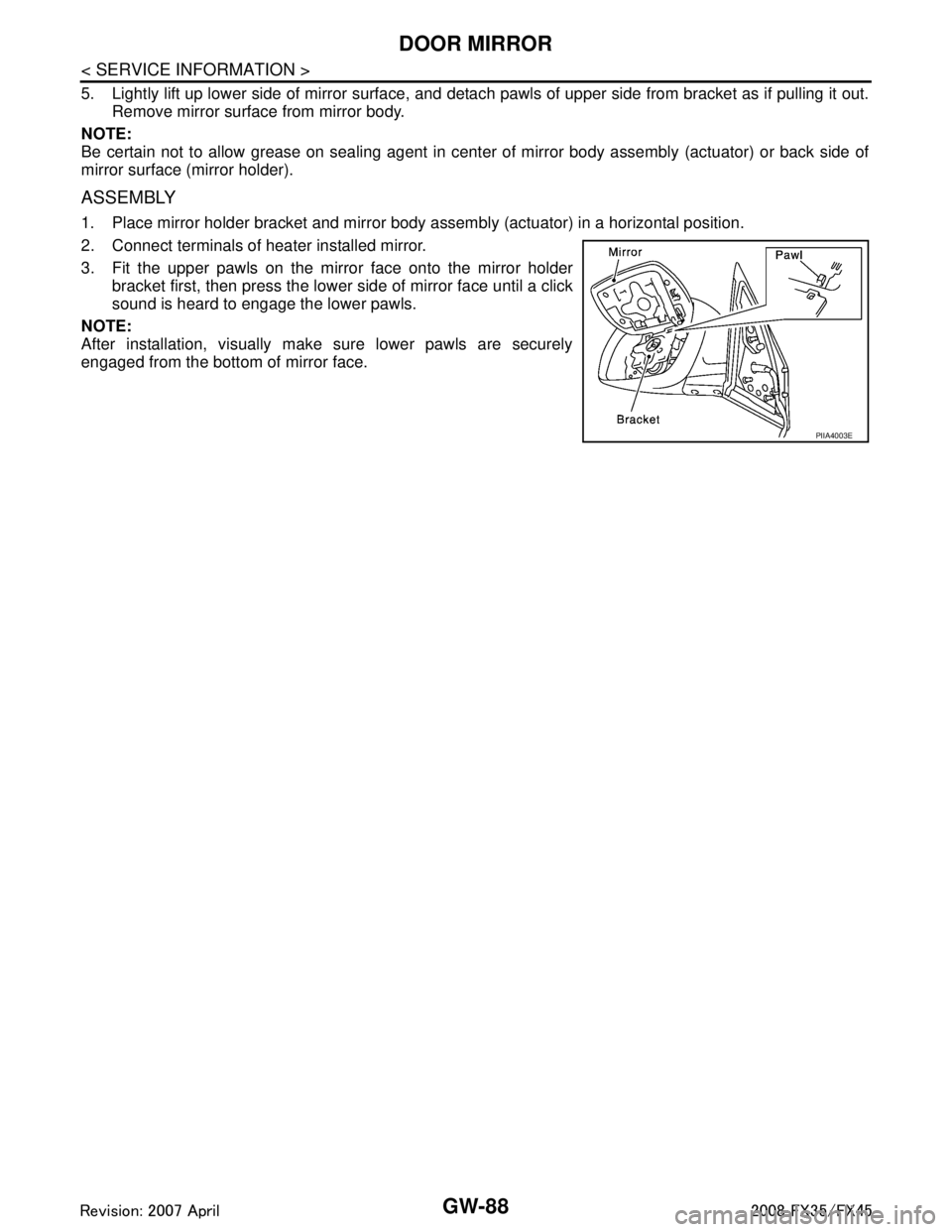
1. Place mirror holder bracket and mirror body assembly (actuator) in a horizontal position.
2. Connect terminals of heater installed mirror.
3. Fit the upper pawls on the mirror face onto the mirror holder bracket first, then press the lower side of mirror face until a click
sound is heard to engage the lower pawls.
NOTE:
After installation, visually make sure lower pawls are securely
engaged from the bottom of mirror face.
PIIA4003E
3AA93ABC3ACD3AC03ACA3AC03AC63AC53A913A773A893A873A873A8E3A773A983AC73AC93AC03AC3
3A893A873A873A8F3A773A9D3AAF3A8A3A8C3A863A9D3AAF3A8B3A8C
Page 3005 of 3924
IP-4
< SERVICE INFORMATION >
SQUEAK AND RATTLE TROUBLE DIAGNOSES
SQUEAK AND RATTLE TROUBLE DIAGNOSES
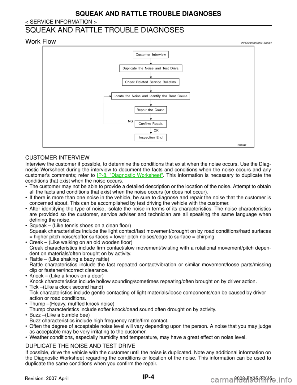
Work FlowINFOID:0000000001328084
CUSTOMER INTERVIEW
Interview the customer if possible, to determine the c onditions that exist when the noise occurs. Use the Diag-
nostic Worksheet during the interview to document the facts and conditions when the noise occurs and any
customer's comments; refer to IP-8, "
Diagnostic Worksheet". This information is necessary to duplicate the
conditions that exist when the noise occurs.
The customer may not be able to provide a detailed description or the location of the noise. Attempt to obtain all the facts and conditions that exist w hen the noise occurs (or does not occur).
If there is more than one noise in the vehicle, be sure to diagnose and repair the noise that the customer is
concerned about. This can be accomplished by te st driving the vehicle with the customer.
After identifying the type of noise, isolate the noise in terms of its characteristics. The noise characteristics
are provided so the customer, service adviser and technician are all speaking the same language when
defining the noise.
Squeak – (Like tennis shoes on a clean floor)
Squeak characteristics include the light contact/fast movement/brought on by road conditions/hard surfaces
= higher pitch noise/softer surfaces = lower pitch noises/edge to surface = chirping
Creak – (Like walking on an old wooden floor)
Creak characteristics include firm contact/slow mo vement/twisting with a rotational movement/pitch depen-
dent on materials/often brought on by activity.
Rattle – (Like shaking a baby rattle)
Rattle characteristics include the fast repeated contac t/vibration or similar movement/loose parts/missing
clip or fastener/incorrect clearance.
Knock – (Like a knock on a door)
Knock characteristics include hollow sounding/someti mes repeating/often brought on by driver action.
Tick –(Like a clock second hand) Tick characteristics include gentle contacting of light materials/loose components/can be caused by driver
action or road conditions.
Thump –(Heavy, muffled knock noise) Thump characteristics include softer k nock/dead sound often drought on by activity.
Buzz –(Like a bumble bee)
Buzz characteristics include hi gh frequency rattle/firm contact.
Often the degree of acceptable noise level will vary depending upon the person. A noise that you may judge as acceptable may be very irritating to the customer.
Weather conditions, especially humidity and temperat ure, may have a great effect on noise level.
DUPLICATE THE NOISE AND TEST DRIVE
If possible, drive the vehicle with the customer until the noise is duplicated. Note any additional information on
the Diagnostic Worksheet regarding the conditions or lo cation of the noise. This information can be used to
duplicate the same conditions when you confirm the repair.
SBT842
3AA93ABC3ACD3AC03ACA3AC03AC63AC53A913A773A893A873A873A8E3A773A983AC73AC93AC03AC3
3A893A873A873A8F3A773A9D3AAF3A8A3A8C3A863A9D3AAF3A8B3A8C
Page 3006 of 3924
SQUEAK AND RATTLE TROUBLE DIAGNOSESIP-5
< SERVICE INFORMATION >
C
DE
F
G H
J
K L
M A
B
IP
N
O P
If the noise can be duplicated easily during the test drive, to help identify the source of the noise, try to dupli-
cate the noise with the vehicle stopped by doing one or all of the following:
1) Close a door.
2) Tap or push/pull around the area where the noise appears to be coming from.
3) Rev the engine.
4) Use a floor jack to recreate vehicle “twist”.
5) At idle, apply engine load (electrical load, half- clutch on M/T model, drive position on A/T model).
6) Raise the vehicle on a hoist and hit a tire with a rubber hammer.
Drive the vehicle and attempt to duplicate the conditions the customer states exist when the noise occurs.
If it is difficult to duplicate the noise, drive the vehicle slowly on an undulating or rough road to stress the vehicle body.
CHECK RELATED SERVICE BULLETINS
After verifying the customer concern or symptom, che ck ASIST for Technical Service Bulletins (TSBs) related
to that concern or symptom.
If a TSB relates to the symptom, follow the procedure to repair the noise.
LOCATE THE NOISE AND IDENTIFY THE ROOT CAUSE
1. Narrow down the noise to a general area. To help pinpoint the source of the noise, use a listening tool (Chassis Ear: J39570, Engine Ea r and mechanics stethoscope).
2. Narrow down the noise to a more specific area and identify the cause of the noise by:
Removing the components in the area that you suspect the noise is coming from.
Do not use too much force when removing clips and fasteners, otherwise clips and fastener can be broken
or lost during the repair, resulting in the creation of new noise.
Tapping or pushing/pulling the component that you suspect is causing the noise.
Do not tap or push/pull the component with excessive force, otherwise the noise will be eliminated only tem-
porarily.
Feeling for a vibration with your hand by touching t he component(s) that you suspect is (are) causing the
noise.
Placing a piece of paper between components that you suspect are causing the noise.
Looking for loose components and contact marks. Refer to IP-6, "
Generic Squeak and Rattle Troubleshooting".
REPAIR THE CAUSE
If the cause is a loose component, tighten the component securely.
If the cause is insufficient clearance between components:
- Separate components by repositioning or loosening and retightening the component, if possible.
- Insulate components with a suitable insulator such as urethane pads, foam blocks, felt cloth tape or ure-
thane tape. A NISSAN Squeak and Rattle Kit (J43980) is available through your authorized NISSAN Parts
Department.
CAUTION:
Do not use excessive force as many components are constructed of plastic and may be damaged.
NOTE:
Always check with the Parts Department for the latest parts information.
The following materials are contained in the NISS AN Squeak and Rattle Kit (J43980). Each item can be
ordered separately as needed.
URETHANE PADS [1.5 mm (0.059 in) thick]
Insulates connectors, harness, etc.
76268-9E005: 100 × 135 mm (3.94 × 5.31 in)/ 76884-71L01: 60 × 85 mm (2.36 × 3.35 in)/76884-71L02: 15 ×
25 mm (0.59 × 0.98 in)
INSULATOR (Foam blocks)
Insulates components from contact. Can be used to fill space behind a panel.
73982-9E000: 45 mm (1.77 in) thick, 50 × 50 mm (1.97 × 1.97 in)/73982-50Y00: 10 mm (0.39 in) think, 50
× 50 mm (1.97 × 1.97 in)
INSULATOR (Light foam block)
80845 - 71L00: 30 mm (1.18 in) thick, 30 × 50 mm (1.18 × 1.97 in)
FELT CLOTH TAPE
Used to insulate where movement does not oc cur.Ideal for instrument panel applications.
68370 - 4B000: 15 × 25 mm (0.59 × 0.98 in) pad / 68239-13E00: 5 mm (0.20 in) wide tape roll The following
materials, not found in the kit, can also be used to repair squeaks and rattles.
UHMW (TEFLON) TAPE
3AA93ABC3ACD3AC03ACA3AC03AC63AC53A913A773A893A873A873A8E3A773A983AC73AC93AC03AC3
3A893A873A873A8F3A773A9D3AAF3A8A3A8C3A863A9D3AAF3A8B3A8C