2008 INFINITI FX35 check oil
[x] Cancel search: check oilPage 3586 of 3924
REAR SUSPENSION ASSEMBLYRSU-5
< SERVICE INFORMATION >
C
DF
G H
I
J
K L
M A
B
RSU
N
O P
REAR SUSPENSION ASSEMBLY
On-Vehicle Inspection and ServiceINFOID:0000000001327552
Make sure the mounting conditions (looseness, ba ck lash) of each component and component status (wear,
damage) are normal.
INSPECTION OF BALL JOINT END PLAY
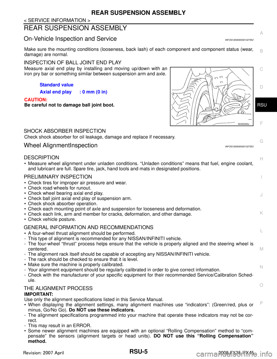
Measure axial end play by installing and moving up/down with an
iron pry bar or something similar between suspension arm and axle.
CAUTION:
Be careful not to damage ball joint boot.
SHOCK ABSORBER INSPECTION
Check shock absorber for oil leakage, damage and replace if necessary.
Wheel AlignmentInspectionINFOID:0000000001327553
DESCRIPTION
Measure wheel alignment under unladen conditions. “U nladen conditions” means that fuel, engine coolant,
and lubricant are full. Spare tire, jack, hand tools and mats in designated positions.
PRELIMINARY INSPECTION
Check tires for improper air pressure and wear.
Check road wheels for runout.
Check wheel bearing axial end play.
Check ball joint axial end play of suspension arm.
Check shock absorber operation.
Check each mounting point of axle and suspension for looseness and deformation.
Check each link, arm and member for cracks, deformation, and other damage.
Check vehicle posture.
GENERAL INFORMATION AND RECOMMENDATIONS
A four-wheel thrust alignment should be performed.
- This type of alignment is recomm ended for any NISSAN/INFINITI vehicle.
- The four-wheel “thrust” process helps ensure that t he vehicle is properly aligned and the steering wheel is
centered.
- The alignment rack itself should be capable of accepting any NISSAN/INFINITI vehicle.
- The rack should be checked to ensure that it is level.
Make sure the machine is properly calibrated.
- Your alignment equipment should be regularly ca librated in order to give correct information.
- Check with the manufacturer of your specific equi pment for their recommended Service/Calibration Sched-
ule.
THE ALIGNMENT PROCESS
IMPORTANT:
Use only the alignment specificati ons listed in this Service Manual.
When displaying the alignment settings, many alignment machines use “indicators”: (Green/red, plus or
minus, Go/No Go). Do NOT use these indicators.
- The alignment specifications programmed into your machine that operate these indicators may not be cor-
rect.
- This may result in an ERROR.
Some newer alignment machines are equipped with an optional “Rolling Compensation” method to “com-
pensate” the sensors (alignment targets or head units). DO NOT use this “Rolling Compensation”
method. Standard value
Axial end play : 0 mm (0 in)
SEIA0245J
3AA93ABC3ACD3AC03ACA3AC03AC63AC53A913A773A893A873A873A8E3A773A983AC73AC93AC03AC3
3A893A873A873A8F3A773A9D3AAF3A8A3A8C3A863A9D3AAF3A8B3A8C
Page 3589 of 3924
RSU-8
< SERVICE INFORMATION >
REAR SUSPENSION ASSEMBLY
REMOVAL
1. Remove tires from vehicle with power tool.
2. Remove brake caliper with power tool. Hang it in a place where it will not interfere with work. Refer to BR-
24.
NOTE:
Avoid depressing brake pedal while brake caliper is removed.
3. Remove wheel sensor from rear final drive, t hen remove wheel sensor harness from rear suspension
member.
4. Remove height sensor harness from rear suspension member (if equipped).
5. Remove center muffler and main muffler. Refer to EX-3, "
Component".
6. Remove stabilizer bar. Refer to RSU-16, "
Removal and Installation".
7. Remove rear propeller shaft. Refer to PR-9, "
Removal and Installation".
8. Separate attachments between parking brake cable and vehicle and rear suspension member.
9. Remove rear lower link and coil spring. Refer to RSU-14, "
Removal and Installation".
10. Remove fixing bolt in lower side of shock absorber with power tool.
11. Set jack under rear final drive.
12. Remove fixing bolts and nuts of tunnel stay and mem ber stay with power tool, then remove those parts
from vehicle.
13. Remove fixing bolts and nuts of rear pin stay with pow er tool and then remove rear pin stay from vehicle.
14. Gradually lowering jack, remove rear suspension assembly.
INSTALLATION
Refer to "Removal and installation" for tightening torque. Install in the reverse order of removal.
NOTE:
Refer to component parts location and do not reuse non-reusable parts.
Perform final tightening of installation position of links (rubber bushing) under unladen conditions with tires on level ground. Check wheel alignment. Refer to RSU-5, "
Wheel AlignmentInspection".
After adjusting wheel alignment, adjust neutral position of steering angle sensor. Refer to BRC-8, "
Adjust-
ment of Steering Angle Sensor Neutral Position".
19. Suspension arm 20. Stabilizer connecting rod mounting
bracket21. Stabilizer connecting rod
22. Rear pin stay 23. Rear suspension member 24. Stabilizer bar
25. Stabilizer bushing 26. Stabilizer clamp 27. Member stay
28. Tunnel stay A: With height sensor B: Without height sensor
Refer to GI-8, "
Component", for the symbols in the figure.
3AA93ABC3ACD3AC03ACA3AC03AC63AC53A913A773A893A873A873A8E3A773A983AC73AC93AC03AC3
3A893A873A873A8F3A773A9D3AAF3A8A3A8C3A863A9D3AAF3A8B3A8C
Page 3590 of 3924
SHOCK ABSORBERRSU-9
< SERVICE INFORMATION >
C
DF
G H
I
J
K L
M A
B
RSU
N
O P
SHOCK ABSORBER
Removal and InstallationINFOID:0000000001327555
REMOVAL
1. Remove tires from vehicle with power tool.
2. Set jack under rear lower link.
3. Remove fixing bolt in lower side of shock absorber assembly with power tool.
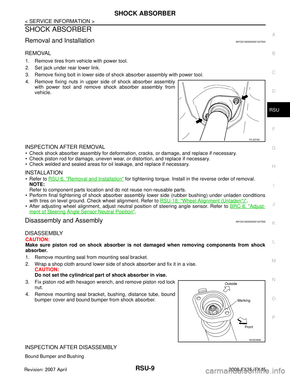
4. Remove fixing nuts in upper side of shock absorber assembly with power tool and remove shock absorber assembly from
vehicle.
INSPECTION AFTER REMOVAL
Check shock absorber assembly for deformation, cracks, or damage, and replace if necessary.
Check piston rod for damage, uneven wear, or distortion, and replace if necessary.
Check welded and sealed areas for oil leakage, and replace if necessary.
INSTALLATION
Refer to RSU-6, "Removal and Installation" for tightening torque. Install in the reverse order of removal.
NOTE:
Refer to component parts location and do not reuse non-reusable parts.
Perform final tightening of shock absorber assembly lower side (rubber b\
ushing) under unladen conditions
with tires on level ground. Check wheel alignment. Refer to RSU-18, "
Wheel Alignment (Unladen*)".
After adjusting wheel alignment, adjust neutral position of steering angle sensor. Refer to BRC-8, "
Adjust-
ment of Steering Angle Sensor Neutral Position".
Disassembly and AssemblyINFOID:0000000001327556
DISASSEMBLY
CAUTION:
Make sure piston rod on shock absorber is not damaged when removing components from shock
absorber.
1. Remove mounting seal fr om mounting seal bracket.
2. Wrap a shop cloth around lower side of shock absorber and fix it in a vise. CAUTION:
Do not set the cylindrical part of shock absorber in vise.
3. Fix piston rod with hexagon wrench, and remove piston rod lock nut.
4. Remove mounting seal bracke t, bushing, distance tube, bound
bumper cover and bound bumper from shock absorber.
INSPECTION AFTER DISASSEMBLY
Bound Bumper and Bushing
FA-0274D
SEIA0366E
3AA93ABC3ACD3AC03ACA3AC03AC63AC53A913A773A893A873A873A8E3A773A983AC73AC93AC03AC3
3A893A873A873A8F3A773A9D3AAF3A8A3A8C3A863A9D3AAF3A8B3A8C
Page 3596 of 3924
REAR LOWER LINK & COIL SPRINGRSU-15
< SERVICE INFORMATION >
C
DF
G H
I
J
K L
M A
B
RSU
N
O P
REAR LOWER LINK & COIL SPRING
Removal and InstallationINFOID:0000000001327560
REMOVAL
1. Remove tire with power tool.
2. Set jack under rear lower link.
3. Loosen fixing bolt and nut between rear lower link and suspension member, and then remove fixing bolt and nut between rear axle and rear lower link with power tool.
4. Slowly lower jack, then remove upper seat, co il spring and rubber seat from rear lower link.
5. Remove fixing bolt and nut between rear suspensi on member and rear lower link with power tool.
INSPECTION AFTER REMOVAL
Check rear lower link, bushing and coil spring for deformation, cracks, and damage. Replace rear lower link
and coil spring if necessary.
INSTALLATION
Refer to RSU-6, "Removal and Installation"for tightening torque. Install in the reverse order of removal.
CAUTION:
Refer to component parts location an d do not reuse non-reusable parts.
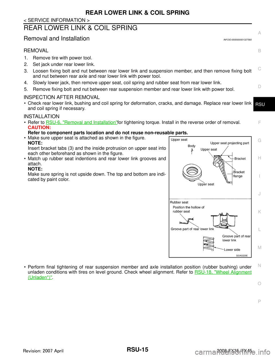
Make sure upper seat is attached as shown in the figure.
NOTE:
Insert bracket tabs (3) and the inside protrusion on upper seat into
each other beforehand as shown in the figure.
Match up rubber seat indentions and rear lower link grooves and
attach.
NOTE:
Make sure spring is not upside down. The top and bottom are indi-
cated by paint color.
Perform final tightening of rear suspension mem ber and axle installation position (rubber bushing) under
unladen conditions with tires on level ground. Check wheel alignment. Refer to RSU-18, "
Wheel Alignment
(Unladen*)".
SEIA0229E
3AA93ABC3ACD3AC03ACA3AC03AC63AC53A913A773A893A873A873A8E3A773A983AC73AC93AC03AC3
3A893A873A873A8F3A773A9D3AAF3A8A3A8C3A863A9D3AAF3A8B3A8C
Page 3598 of 3924
REAR SUSPENSION MEMBERRSU-17
< SERVICE INFORMATION >
C
DF
G H
I
J
K L
M A
B
RSU
N
O P
REAR SUSPENSION MEMBER
Removal and InstallationINFOID:0000000001327562
REMOVAL
1. Remove tires from vehicle with power tool.
2. Remove brake caliper with power tool. Hang it in a place where it will not interfere with work. Refer to BR-
24.
NOTE:
Avoid depressing brake pedal while brake caliper is removed.
3. Remove wheel sensor from rear final drive, t hen remove wheel sensor harness from rear suspension
member. Refer to BRC-52
.
4. Remove height sensor harness from rear suspension member (if equipped).
5. Remove center muffler and main muffler. Refer to EX-3
.
6. Remove stabilizer bar. Refer to RSU-16, "
Removal and Installation".
7. Remove rear drive shaft. Refer to RAX-10
.
8. Remove propeller shaft. Refer to PR-7
.
9. Remove rear final drive. Refer to RFD-16, "
Removal and Installation".
10. Separate attachments between parking brake cable and vehicle and rear suspension member. Refer to PB-4
.
11. Remove rear lower link and coil spring. Refer to RSU-14, "
Removal and Installation".
12. Remove fixing bolt in lower side of shock absorber with power tool.
13. Set jack under rear suspension member.
14. Remove fixing bolts and nuts of tunnel stay and member stay with power tool, then remove those parts from vehicle and rear suspension member.
15. Remove fixing bolts and nuts of rear pin stay with pow er tool and then remove rear pin stay from vehicle
and rear suspension member.
16. Slowly lowering jack, then remove rear suspension me mber, suspension arm, radius rod, front lower link
and axle from vehicle as a unit.
17. Remove fixing bolts and nuts with power tool, then re move suspension arm, front lower link, and radius
rod from rear suspension member.
INSPECTION AFTER REMOVAL
Check rear suspension member for deformation, cracks, and other damage and replace if necessary.
INSTALLATION
Refer to RSU-6, "Removal and Installation", for tightening torque. Install in the reverse order of removal.
NOTE:
Refer to component parts location and do not reuse non-reusable parts.
Perform final tightening of installation position of links (rubber bushing) under unladen conditions with tires
on level ground. Check wheel alignment. Refer to RSU-5, "
Wheel AlignmentInspection".
After adjusting wheel alignment, adjust neutral position of steering angle sensor. Refer to BRC-8, "
Adjust-
ment of Steering Angle Sensor Neutral Position".
3AA93ABC3ACD3AC03ACA3AC03AC63AC53A913A773A893A873A873A8E3A773A983AC73AC93AC03AC3
3A893A873A873A8F3A773A9D3AAF3A8A3A8C3A863A9D3AAF3A8B3A8C
Page 3601 of 3924
SB-2
< SERVICE INFORMATION >
PRECAUTIONS
SERVICE INFORMATION
PRECAUTIONS
Precaution for Supplemental Restraint System (SRS) "AIR BAG" and "SEAT BELT
PRE-TENSIONER"
INFOID:0000000001612908
The Supplemental Restraint System such as “A IR BAG” and “SEAT BELT PRE-TENSIONER”, used along
with a front seat belt, helps to reduce the risk or severi ty of injury to the driver and front passenger for certain
types of collision. This system includes seat belt switch inputs and dual stage front air bag modules. The SRS
system uses the seat belt switches to determine the front air bag deployment, and may only deploy one front
air bag, depending on the severity of a collision and w hether the front occupants are belted or unbelted.
Information necessary to service the system safely is included in the “SUPPLEMENTAL RESTRAINT SYS-
TEM” and “SEAT BELTS” of this Service Manual.
WARNING:
• To avoid rendering the SRS inopera tive, which could increase the risk of personal injury or death in
the event of a collision which would result in air bag inflation, all maintenance must be performed by
an authorized NISS AN/INFINITI dealer.
Improper maintenance, including in correct removal and installation of the SRS, can lead to personal
injury caused by unintent ional activation of the system. For re moval of Spiral Cable and Air Bag
Module, see the “SUPPLEMEN TAL RESTRAINT SYSTEM”.
Do not use electrical test equipmen t on any circuit related to the SRS unless instructed to in this
Service Manual. SRS wiring harnesses can be identi fied by yellow and/or orange harnesses or har-
ness connectors.
Precaution for Seat Belt ServiceINFOID:0000000001327733
CAUTION:
Before removing the front seat belt pre-tensione r assembly, turn the ignition switch off, disconnect
the both battery cables and wait at least 3 minutes.
Do not use electrical test equipment for front seat belt pre-tensioner connector.
After replacing or reinstalling front seat belt pr e-tensioner assembly, or reconnecting front seat belt
pre-tensioner connector, check the system function. Refer to SRS-23, "
SRS Operation Check".
Do not use disassemble buckle or seat belt assembly.
Replace anchor bolts if they are deformed or worn out.
Never oil tongue and buckle.
If any component of seat belt assembly is questionable, do not re pair. Replace the whole seat belt
assembly.
If webbing is cut, frayed, or damaged, replace seat belt assembly.
When replacing seat belt assembly, use a genuine NISSAN seat belt assembly.
Disposal, recycling, and transportation of air ba g modules and seat belt pre-tensioners should be
performed in compliance with applicable fede ral, state and local laws and regulations.
AFTER A COLLISION
WARNING:
Inspect all seat belt assemblies including retractors and attaching hardware after any collision.
NISSAN recommends that all seat belt assemblies in use during a collision be replaced unless the col-
lision was minor and the belts show no damage and continue to operate properly. Failure to do so
could result in serious personal injury in an acci dent. Seat belt assemblies not in use during a colli-
sion should also be replaced if either damage or im proper operation is noted. Seat belt pre-tensioner
should be replaced even if the seat belts are not in use during a frontal collision in which the air bags
are deployed.
Replace any seat belt assembly (including anchor bolts) if:
The seat belt was in use at the time of a collision (except for minor collisions and the belts, retractors and
buckles show no damage and continue to operate properly).
The seat belt was damaged in an accident. (i.e. torn webbing, bent retractor or guide).
The seat belt attaching point was damaged in an acci dent. Inspect the seat belt attaching area for damage
or distortion and repair as necessary before installing a new seat belt assembly.
Anchor bolts are deformed or worn out.
The front seat belt pre-tensioner should be replaced even if the seat belts are not in use during the collision
in which the air bags are deployed.
3AA93ABC3ACD3AC03ACA3AC03AC63AC53A913A773A893A873A873A8E3A773A983AC73AC93AC03AC3
3A893A873A873A8F3A773A9D3AAF3A8A3A8C3A863A9D3AAF3A8B3A8C
Page 3772 of 3924
DRIVER AIR BAG MODULESRS-35
< SERVICE INFORMATION >
C
DE
F
G
I
J
K L
M A
B
SRS
N
O P
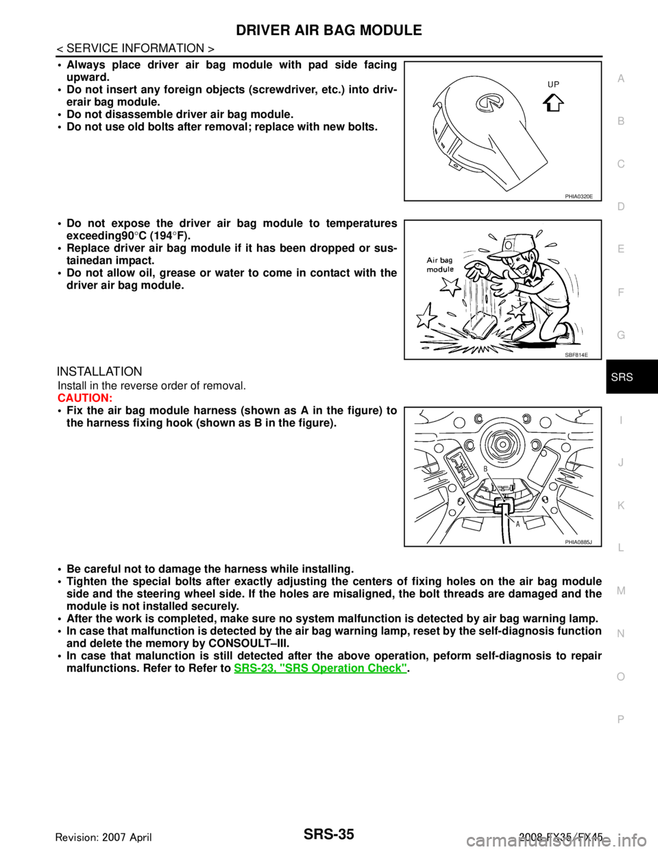
Always place driver air bag module with pad side facing upward.
Do not insert any foreign objects (screwdriver, etc.) into driv-
erair bag module.
Do not disassemble driver air bag module.
Do not use old bolts after removal; replace with new bolts.
Do not expose the driver air bag module to temperatures exceeding90 °C (194 °F).
Replace driver air bag module if it has been dropped or sus-
tainedan impact.
Do not allow oil, grease or water to come in contact with the
driver air bag module.
INSTALLATION
Install in the reverse order of removal.
CAUTION:
Fix the air bag module harness (shown as A in the figure) to
the harness fixing hook (s hown as B in the figure).
Be careful not to damage the harness while installing.
Tighten the special bolts after exactly adjusting the centers of fi xing holes on the air bag module
side and the steering wheel side. If the holes are misaligned, the bolt threads are damaged and the
module is not installed securely.
After the work is completed, make sure no system malfunction is detected by air bag warning lamp.
In case that malfunction is detected by the air ba g warning lamp, reset by the self-diagnosis function
and delete the memory by CONSOULT–III.
In case that malunction is still detected after th e above operation, peform self-diagnosis to repair
malfunctions. Refer to Refer to SRS-23, "
SRS Operation Check".
PHIA0320E
SBF814E
PHIA0885J
3AA93ABC3ACD3AC03ACA3AC03AC63AC53A913A773A893A873A873A8E3A773A983AC73AC93AC03AC3
3A893A873A873A8F3A773A9D3AAF3A8A3A8C3A863A9D3AAF3A8B3A8C
Page 3776 of 3924
FRONT PASSENGER AIR BAG MODULESRS-39
< SERVICE INFORMATION >
C
DE
F
G
I
J
K L
M A
B
SRS
N
O P
Replace front passenger air bag module if it has been dropped or sustained an impact.
Do not expose the front passenger air bag module to tempera-
tures exceeding 90 °C (194 °F).
Do not allow oil, grease or water to come in contact with the
front passenger air bag module.
After front passenger air bag module inflates, the instrument
panel assembly should be replaced.
INSTALLATION
Install in the reverse order of removal.
CAUTION:
Be careful not to damage the harness while installing.
After the work is completed, make sure no system malfunction is detected by air bag warning lamp.
In case that malfunction is detected by the air ba g warning lamp, reset by the self-diagnosis function
and delete the memory by CONSULT −III.
In case that malfunction is still detected after th e above operation, perform self-diagnosis to repair
malfunctions. Refer to Refer to SRS-23, "
SRS Operation Check".
SBF814E
3AA93ABC3ACD3AC03ACA3AC03AC63AC53A913A773A893A873A873A8E3A773A983AC73AC93AC03AC3
3A893A873A873A8F3A773A9D3AAF3A8A3A8C3A863A9D3AAF3A8B3A8C