2008 INFINITI FX35 lock
[x] Cancel search: lockPage 1222 of 3924
DI-96
< SERVICE INFORMATION >
COMPASS
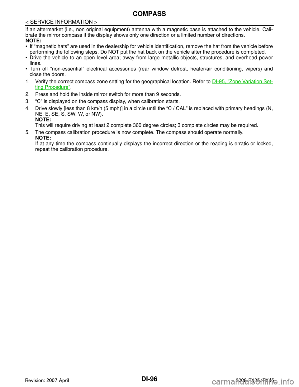
if an aftermarket (i.e., non original equipment) antenna with a magnetic base is attached to the vehicle. Cali-
brate the mirror compass if the display shows onl y one direction or a limited number of directions.
NOTE:
If “magnetic hats” are used in the dealership for vehicle identification, remove the hat from the vehicle before
performing the following steps. Do NOT put the hat back on the vehicle after the procedure is completed.
Drive the vehicle to an open level area; away from large metallic objects, structures, and overhead power
lines.
Turn off “non-essential” electrical accessories (r ear window defrost, heater/air conditioning, wipers) and
close the doors.
1. Verify the correct compass zone setting for the geographical location. Refer to DI-95, "
Zone Variation Set-
ting Procedure".
2. Press and hold the inside mirror switch for more than 9 seconds.
3. “C” is displayed on the compass display, when calibration starts.
4. Drive slowly [less than 8 km/h (5 mph)] in a circle until the “C / CAL” is replaced with primary headings (N,
NE, E, SE, S, SW, W, or NW).
NOTE:
This will require driving at least 2 complete 360 degree circles; 3 complete circles may be required.
5. The compass calibration procedure is now complete. The compass should operate normally. NOTE:
If at any time the compass continually displays the in correct direction or the reading is erratic or locked,
repeat the calibration procedure.
3AA93ABC3ACD3AC03ACA3AC03AC63AC53A913A773A893A873A873A8E3A773A983AC73AC93AC03AC3
3A893A873A873A8F3A773A9D3AAF3A8A3A8C3A863A9D3AAF3A8B3A8C
Page 1224 of 3924
DI-98
< SERVICE INFORMATION >
CLOCK
CLOCK
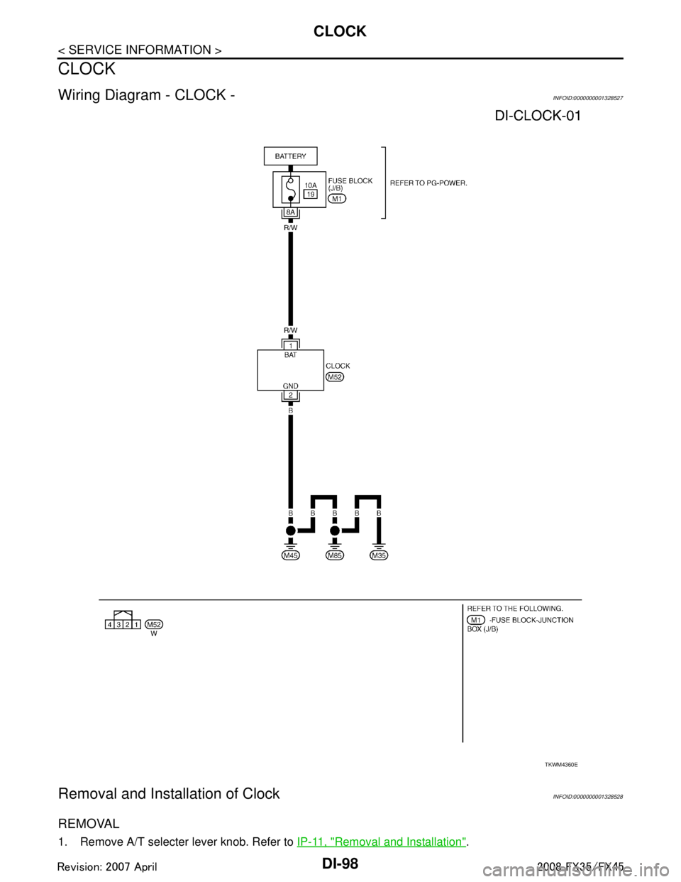
Wiring Diagram - CLOCK -INFOID:0000000001328527
Removal and Installation of ClockINFOID:0000000001328528
REMOVAL
1. Remove A/T selecter lever knob. Refer to IP-11, "Removal and Installation".
TKWM4360E
3AA93ABC3ACD3AC03ACA3AC03AC63AC53A913A773A893A873A873A8E3A773A983AC73AC93AC03AC3
3A893A873A873A8F3A773A9D3AAF3A8A3A8C3A863A9D3AAF3A8B3A8C
Page 1225 of 3924
CLOCKDI-99
< SERVICE INFORMATION >
C
DE
F
G H
I
J
L
M A
B
DI
N
O P
2. Remove A/T console finisher. Refer to IP-11, "Removal and Installation".
3. Remove instrument clock finisher. Refer to IP-11, "
Removal and Installation".
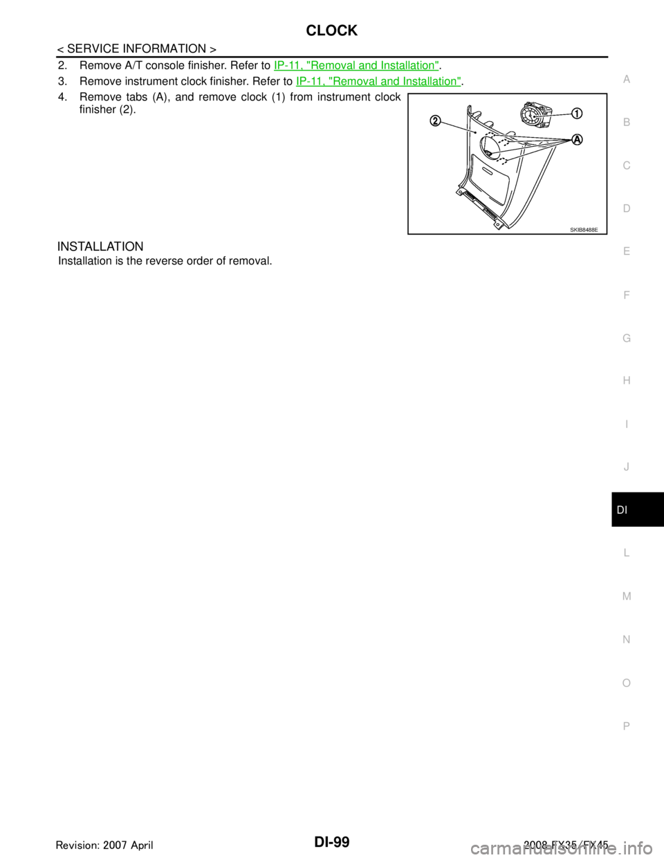
4. Remove tabs (A), and remove clock (1) from instrument clock finisher (2).
INSTALLATION
Installation is the reverse order of removal.
SKIB8488E
3AA93ABC3ACD3AC03ACA3AC03AC63AC53A913A773A893A873A873A8E3A773A983AC73AC93AC03AC3
3A893A873A873A8F3A773A9D3AAF3A8A3A8C3A863A9D3AAF3A8B3A8C
Page 1226 of 3924
DI-100
< SERVICE INFORMATION >
REAR VIEW MONITOR
REAR VIEW MONITOR
System DescriptionINFOID:0000000001328529
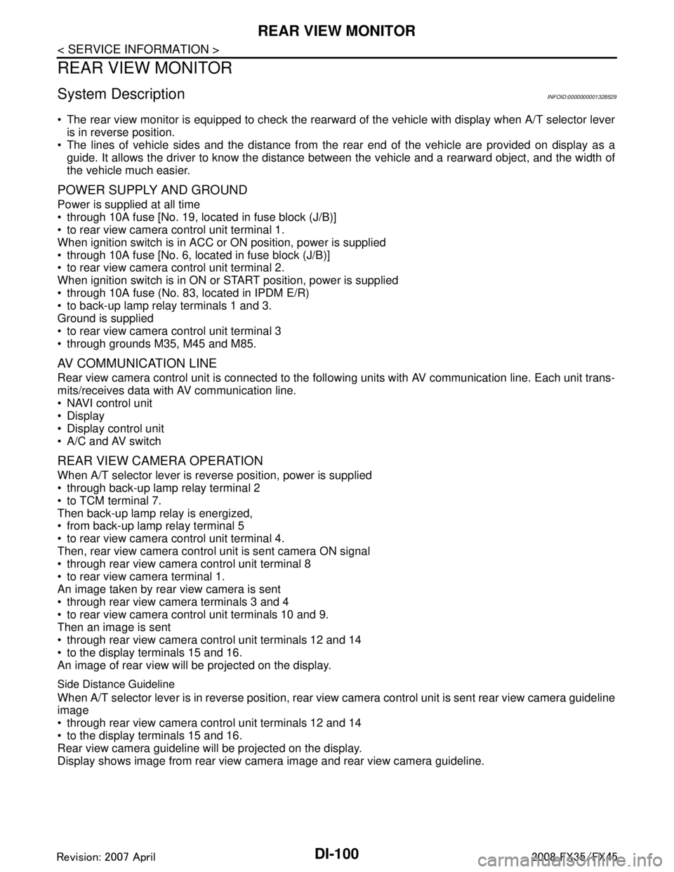
The rear view monitor is equipped to check the rearward of the vehicle with display when A/T selector leveris in reverse position.
The lines of vehicle sides and the distance from the rear end of the vehicle are provided on display as a
guide. It allows the driver to know the distance bet ween the vehicle and a rearward object, and the width of
the vehicle much easier.
POWER SUPPLY AND GROUND
Power is supplied at all time
through 10A fuse [No. 19, located in fuse block (J/B)]
to rear view camera control unit terminal 1.
When ignition switch is in ACC or ON position, power is supplied
through 10A fuse [No. 6, located in fuse block (J/B)]
to rear view camera control unit terminal 2.
When ignition switch is in ON or START position, power is supplied
through 10A fuse (No. 83, located in IPDM E/R)
to back-up lamp relay terminals 1 and 3.
Ground is supplied
to rear view camera control unit terminal 3
through grounds M35, M45 and M85.
AV COMMUNICATION LINE
Rear view camera control unit is connected to the foll owing units with AV communication line. Each unit trans-
mits/receives data with AV communication line.
NAVI control unit
Display
Display control unit
A/C and AV switch
REAR VIEW CAMERA OPERATION
When A/T selector lever is reverse position, power is supplied
through back-up lamp relay terminal 2
to TCM terminal 7.
Then back-up lamp relay is energized,
from back-up lamp relay terminal 5
to rear view camera control unit terminal 4.
Then, rear view camera control unit is sent camera ON signal
through rear view camera control unit terminal 8
to rear view camera terminal 1.
An image taken by rear view camera is sent
through rear view camera terminals 3 and 4
to rear view camera control unit terminals 10 and 9.
Then an image is sent
through rear view camera control unit terminals 12 and 14
to the display terminals 15 and 16.
An image of rear view will be projected on the display.
Side Distance Guideline
When A/T selector lever is in reverse position, rear view camera control unit is sent rear view camera guideline
image
through rear view camera control unit terminals 12 and 14
to the display terminals 15 and 16.
Rear view camera guideline will be projected on the display.
Display shows image from rear view camera image and rear view camera guideline.
3AA93ABC3ACD3AC03ACA3AC03AC63AC53A913A773A893A873A873A8E3A773A983AC73AC93AC03AC3
3A893A873A873A8F3A773A9D3AAF3A8A3A8C3A863A9D3AAF3A8B3A8C
Page 1239 of 3924
REAR VIEW MONITORDI-113
< SERVICE INFORMATION >
C
DE
F
G H
I
J
L
M A
B
DI
N
O P
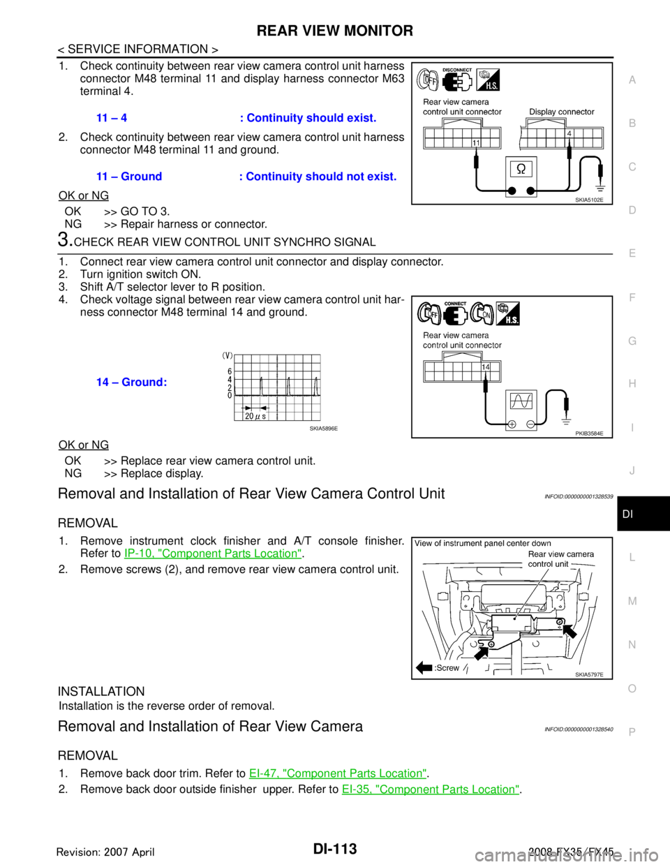
1. Check continuity between rear view camera control unit harness connector M48 terminal 11 and display harness connector M63
terminal 4.
2. Check continuity between rear view camera control unit harness connector M48 terminal 11 and ground.
OK or NG
OK >> GO TO 3.
NG >> Repair harness or connector.
3.CHECK REAR VIEW CONTROL UNIT SYNCHRO SIGNAL
1. Connect rear view camera control unit connector and display connector.
2. Turn ignition switch ON.
3. Shift A/T selector lever to R position.
4. Check voltage signal between rear view camera control unit har- ness connector M48 terminal 14 and ground.
OK or NG
OK >> Replace rear view camera control unit.
NG >> Replace display.
Removal and Installation of R ear View Camera Control UnitINFOID:0000000001328539
REMOVAL
1. Remove instrument clock finisher and A/T console finisher.
Refer to IP-10, "
Component Parts Location".
2. Remove screws (2), and remove rear view camera control unit.
INSTALLATION
Installation is the reverse order of removal.
Removal and Installation of Rear View CameraINFOID:0000000001328540
REMOVAL
1. Remove back door trim. Refer to EI-47, "Component Parts Location".
2. Remove back door outside finisher upper. Refer to EI-35, "
Component Parts Location".
11 – 4 : Continuity should exist.
11 – Ground : Continuity should not exist.
SKIA5102E
14 – Ground:
PKIB3584ESKIA5896E
SKIA5797E
3AA93ABC3ACD3AC03ACA3AC03AC63AC53A913A773A893A873A873A8E3A773A983AC73AC93AC03AC3
3A893A873A873A8F3A773A9D3AAF3A8A3A8C3A863A9D3AAF3A8B3A8C
Page 1259 of 3924
![INFINITI FX35 2008 Service Manual
INDEX FOR DTCEC-19
< SERVICE INFORMATION > [VQ35DE]
C
D
E
F
G H
I
J
K L
M A
EC
NP
OP0460 0460 FUEL LEV SEN SLOSH
EC-401
P0461 0461 FUEL LEVEL SENSOREC-403
P0462 0462 FUEL LEVL SEN/CIRCEC-405
P0463 04 INFINITI FX35 2008 Service Manual
INDEX FOR DTCEC-19
< SERVICE INFORMATION > [VQ35DE]
C
D
E
F
G H
I
J
K L
M A
EC
NP
OP0460 0460 FUEL LEV SEN SLOSH
EC-401
P0461 0461 FUEL LEVEL SENSOREC-403
P0462 0462 FUEL LEVL SEN/CIRCEC-405
P0463 04](/manual-img/42/57017/w960_57017-1258.png)
INDEX FOR DTCEC-19
< SERVICE INFORMATION > [VQ35DE]
C
D
E
F
G H
I
J
K L
M A
EC
NP
OP0460 0460 FUEL LEV SEN SLOSH
EC-401
P0461 0461 FUEL LEVEL SENSOREC-403
P0462 0462 FUEL LEVL SEN/CIRCEC-405
P0463 0463 FUEL LEVL SEN/CIRCEC-405
P0500 0500
VEH SPEED SEN/CIRC*5EC-407
P0506 0506 ISC SYSTEM EC-409
P0507 0507 ISC SYSTEM EC-411
P0550 0550 PW ST P SEN/CIRCEC-413
P0603 0603 ECM BACK UP/CIRCUITEC-418
P0605 0605 ECMEC-422
P0643 0643 SENSOR POWER/CIRCEC-424
P0700 0700 TCM AT- 1 0 1
P0705 0705 PNP SW/CIRCAT- 1 0 2
P0710 0710 ATF TEMP SEN/CIRCAT- 1 3 2
P0717 0717 TURBINE SENSORAT- 1 0 6
P0720 0720
VEH SPD SEN/CIR AT*5AT- 1 0 8
P0731 0731 A/T 1ST GR FNCTN AT- 11 4
P0732 0732 A/T 2ND GR FNCTNAT- 11 6
P0733 0733 A/T 3RD GR FNCTNAT- 11 8
P0734 0734 A/T 4TH GR FNCTNAT- 1 2 0
P0735 0735 A/T 5TH GR FNCTNAT- 1 2 2
P0740 0740 TCC SOLENOID/CIRCAT- 1 2 4
P0744 0744 A/T TCC S/V FNCTNAT- 1 2 6
P0745 0745 L/PRESS SOL/CIRCAT- 1 2 8
P0850 0850 P-N POS SW/CIRCUITEC-429
P1148 1148 CLOSED LOOP-B1EC-434
P1168 1168 CLOSED LOOP-B2EC-434
P1211 1211 TCS C/U FUNCTNEC-435
P1212 1212 TCS/CIRC EC-436
P1217 1217 ENG OVER TEMPEC-437
P1225 1225 CTP LEARNING-B1EC-447
P1226 1226 CTP LEARNING-B1EC-449
P1421 1421 COLD START CONTROLEC-451
P1564 1564 ASCD SWEC-453 (Models with ICC),
EC-459
(Models with ASCD)
P1568 1568 ICC COMMAND VALUE*
6EC-464
P1572 1572 ASCD BRAKE SW EC-465 (Models with ICC),
EC-474
(Models with ASCD)
P1574 1574 ASCD VHL SPD SEN EC-481
(Models with ICC),
EC-483
(Models with ASCD)
P1610 1610 LOCK MODE BL-4
P1611 1611 ID DISCARD IMM-ECMBL-4
P1612 1612 CHAIN OF ECM-IMMU BL-4
DTC*1
Items
(CONSULT-III screen terms) Reference page
CONSULT-III
GST*
2ECM*3
3AA93ABC3ACD3AC03ACA3AC03AC63AC53A913A773A893A873A873A8E3A773A983AC73AC93AC03AC3
3A893A873A873A8F3A773A9D3AAF3A8A3A8C3A863A9D3AAF3A8B3A8C
Page 1260 of 3924
![INFINITI FX35 2008 Service Manual
EC-20
< SERVICE INFORMATION >[VQ35DE]
INDEX FOR DTC
*1: 1st trip DTC No. is
the same as DTC No.
*2: This number is prescribed by SAE J2012.
*3: In Diagnostic Test Mode II (Self-diagnostic results) INFINITI FX35 2008 Service Manual
EC-20
< SERVICE INFORMATION >[VQ35DE]
INDEX FOR DTC
*1: 1st trip DTC No. is
the same as DTC No.
*2: This number is prescribed by SAE J2012.
*3: In Diagnostic Test Mode II (Self-diagnostic results)](/manual-img/42/57017/w960_57017-1259.png)
EC-20
< SERVICE INFORMATION >[VQ35DE]
INDEX FOR DTC
*1: 1st trip DTC No. is
the same as DTC No.
*2: This number is prescribed by SAE J2012.
*3: In Diagnostic Test Mode II (Self-diagnostic results), this number is controlled by NISSAN.
*4: The troubleshooting for this DTC needs CONSULT-III.
*5: When the fail-safe operations for both self-diagnoses occur, the MIL illuminates.
*6: For models with ICC system.
Alphabetical IndexINFOID:0000000001325888
P1614 1614 CHAIN OF IMMU-KEY BL-4
P1615 1615 DIFFERENCE OF KEYBL-4
P1715 1715 IN PULY SPEEDEC-485
P1730 1730 A/T INTERLOCK AT- 1 3 9
P1752 1752 I/C SOLENOID/CIRCAT- 1 4 3
P1757 1757 FR/B SOLENOID/CIRCAT- 1 4 5
P1762 1762 D/C SOLENOID/CIRCAT- 1 4 7
P1767 1767 HLR/C SOL/CIRCAT- 1 4 9
P1772 1772 LC/B SOLENOID/CIRCAT- 1 5 1
P1774 1774 LC/B SOLENOID FNCTAT- 1 5 3
P1805 1805 BRAKE SW/CIRCUITEC-486
P2100 2100 ETC MOT PWR-B1EC-490
P2101 2101 ETC FNCTN/CIRC-B1EC-494
P2103 2103 ETC MOT PWREC-490
P 2 11 8 2 11 8 E T C M O T- B 1EC-500
P 2 11 9 2 11 9 E T C A C T R - B 1EC-504
P2122 2122 APP SEN 1/CIRC EC-506
P2123 2123 APP SEN 1/CIRCEC-506
P2127 2127 APP SEN 2/CIRCEC-512
P2128 2128 APP SEN 2/CIRCEC-512
P2135 2135 TP SENSOR-B1EC-518
P2138 2138 APP SENSOREC-524
P2A00 2A00 A/F SENSOR1 (B1) EC-532
P2A03 2A03 A/F SENSOR1 (B2)EC-532
DTC*1
Items
(CONSULT-III screen terms) Reference page
CONSULT-III
GST*
2ECM*3
Items
(CONSULT-III screen terms) DTC*
1
Reference page
CONSULT-III
GST*
2ECM*3
A/F SEN1 HTR (B1) P0031 0031 EC-153
A/F SEN1 HTR (B1) P0032 0032EC-153
A/F SEN1 HTR (B2) P0051 0051EC-153
A/F SEN1 HTR (B2) P0052 0052EC-153
A/F SENSOR1 (B1) P0130 0130EC-212
A/F SENSOR1 (B1) P0131 0131EC-220
A/F SENSOR1 (B1) P0132 0132EC-228
A/F SENSOR1 (B1) P0133 0133EC-236
3AA93ABC3ACD3AC03ACA3AC03AC63AC53A913A773A893A873A873A8E3A773A983AC73AC93AC03AC3
3A893A873A873A8F3A773A9D3AAF3A8A3A8C3A863A9D3AAF3A8B3A8C
Page 1261 of 3924
![INFINITI FX35 2008 Service Manual
INDEX FOR DTCEC-21
< SERVICE INFORMATION > [VQ35DE]
C
D
E
F
G H
I
J
K L
M A
EC
NP
OA/F SENSOR1 (B1) P2A00 2A00
EC-532
A/F SENSOR1 (B2) P0150 0150EC-212
A/F SENSOR1 (B2) P0151 0151EC-220
A/F SENSOR1 ( INFINITI FX35 2008 Service Manual
INDEX FOR DTCEC-21
< SERVICE INFORMATION > [VQ35DE]
C
D
E
F
G H
I
J
K L
M A
EC
NP
OA/F SENSOR1 (B1) P2A00 2A00
EC-532
A/F SENSOR1 (B2) P0150 0150EC-212
A/F SENSOR1 (B2) P0151 0151EC-220
A/F SENSOR1 (](/manual-img/42/57017/w960_57017-1260.png)
INDEX FOR DTCEC-21
< SERVICE INFORMATION > [VQ35DE]
C
D
E
F
G H
I
J
K L
M A
EC
NP
OA/F SENSOR1 (B1) P2A00 2A00
EC-532
A/F SENSOR1 (B2) P0150 0150EC-212
A/F SENSOR1 (B2) P0151 0151EC-220
A/F SENSOR1 (B2) P0152 0152EC-228
A/F SENSOR1 (B2) P0153 0153EC-236
A/F SENSOR1 (B2) P2A03 2A03EC-532
A/T 1ST GR FNCTN P0731 0731 AT- 11 4
A/T 2ND GR FNCTN P0732 0732AT- 11 6
A/T 3RD GR FNCTN P0733 0733AT- 11 8
A/T 4TH GR FNCTN P0734 0734AT-120
A/T 5TH GR FNCTN P0735 0735AT-122
A/T INTERLOCK P1730 1730AT-139
A/T TCC S/V FNCTN P0744 0744AT-126
APP SEN 1/CIRC P2122 2122EC-506
APP SEN 1/CIRC P2123 2123EC-506
APP SEN 2/CIRC P2127 2127EC-512
APP SEN 2/CIRC P2128 2128EC-512
APP SENSOR P2138 2138EC-524
ASCD BRAKE SW P1572 1572EC-465 (Models with ICC),
EC-474
(Models with ASCD)
ASCD SW P1564 1564 EC-453
(Models with ICC),
EC-459
(Models with ASCD)
ASCD VHL SPD SEN P1574 1574 EC-481
(Models with ICC),
EC-483
(Models with ASCD)
ATF TEMP SEN/CIRC P0710 0710 AT-132
BRAKE SW/CIRCUIT P1805 1805EC-486
CAN COMM CIRCUIT U1000
1000*4EC-146
CAN COMM CIRCUIT U10011001*4EC-146
CHAIN OF ECM-IMMU P1612 1612 BL-4
CHAIN OF IMMU-KEY P1614 1614BL-4
CKP SEN/CIRCUIT P0335 0335EC-319
C L O S E D L O O P - B 1 P 11 4 8 11 4 8EC-434
C L O S E D L O O P - B 2 P 11 6 8 11 6 8EC-434
CMP SEN/CIRC-B1 P0340 0340EC-324
CMP SEN/CIRC-B2 P0345 0345EC-324
COLD START CONTROL P1421 1421EC-451
CONTROL UNIT(CAN) U1010 1010EC-148
CTP LEARNING-B1 P1225 1225EC-447
CTP LEARNING-B1 P1226 1226EC-449
CYL 1 MISFIRE P0301 0301EC-308
CYL 2 MISFIRE P0302 0302EC-308
CYL 3 MISFIRE P0303 0303EC-308
CYL 4 MISFIRE P0304 0304EC-308
Items
(CONSULT-III screen terms) DTC*
1
Reference page
CONSULT-III
GST*
2ECM*3
3AA93ABC3ACD3AC03ACA3AC03AC63AC53A913A773A893A873A873A8E3A773A983AC73AC93AC03AC3
3A893A873A873A8F3A773A9D3AAF3A8A3A8C3A863A9D3AAF3A8B3A8C