2008 INFINITI FX35 lock
[x] Cancel search: lockPage 1124 of 3924
![INFINITI FX35 2008 Service Manual
THERMOSTAT AND WATER CONTROL VALVECO-53
< SERVICE INFORMATION > [VK45DE]
C
D
E
F
G H
I
J
K L
M A
CO
NP
O
Refer to
GI-8, "Component" for symbols in the figure.
Removal and InstallationINFOID:000000 INFINITI FX35 2008 Service Manual
THERMOSTAT AND WATER CONTROL VALVECO-53
< SERVICE INFORMATION > [VK45DE]
C
D
E
F
G H
I
J
K L
M A
CO
NP
O
Refer to
GI-8, "Component" for symbols in the figure.
Removal and InstallationINFOID:000000](/manual-img/42/57017/w960_57017-1123.png)
THERMOSTAT AND WATER CONTROL VALVECO-53
< SERVICE INFORMATION > [VK45DE]
C
D
E
F
G H
I
J
K L
M A
CO
NP
O
Refer to
GI-8, "Component" for symbols in the figure.
Removal and InstallationINFOID:0000000001325885
REMOVAL
1. Drain engine coolant from drain plugs on radiat or and both side of cylinder block. Refer to CO-37, "Chang-
ing Engine Coolant" and EM-242, "Disassembly and Assembly".
CAUTION:
Perform this step when engine is cold.
Do not spill engine coolant on drive belts.
2. Remove engine cover with power tool. Refer to EM-169, "
Component".
3. Remove air duct (inlet). Refer to EM-173, "
Component".
4. Disconnect water suction hose from water inlet.
5. Remove water inlet and thermostat. CAUTION:
Do not disassemble thermostat.
6. Remove intake manifolds (upper and lower). Refer to EM-175, "
Component".
7. Disconnect radiator hose (upper) and wa ter hoses from thermostat housing.
8. Disconnect heater hoses from water outlet and heater pipe.
9. Remove thermostat housing, water outlet pipe, water connector, water control valve, water outlet and heater pipe.
CAUTION:
Do not disassemble water control valve.
INSPECTION AFTER REMOVAL
Make sure that valves both in thermostat and water c ontrol valve are completely closing at normal tempera-
ture.
Place a thread so that it is caught in the valves of the thermostat
and water control valve. Immerse fully in a container filled with
water. Heat while stirring. (The example in the figure shows ther-
mostat.)
The valve opening temperature is the temperature at which the valve opens and falls from the thread.
Continue heating. Check the maximum valve lift. NOTE:
The maximum valve lift standard temperature for water control
valve is the reference value.
After checking the maximum valve lift, lower the water tempera-
ture and check the valve closing temperature.
Standard values:
If the malfunctioning condition, when closing valve at nor mal temperature, or measured values are out of the
standard, replace thermostat and/or water control valve.
INSTALLATION
Note the following, and install in the reverse order of removal.
CAUTION:
Be careful not to spill engine coolant over en gine room. Use rag to absorb engine coolant.
Thermostat and Water Control Valve
D. To heater core E. To cylinder head (left bank) F. To cylinder head (right bank)
G. To intake manifold adapter
SLC252B
Thermostat Water control valve
Valve opening temperature 80 - 84 °C (176 - 183 °F) 93.5 - 96.5 °C (200 - 206 °F)
Maximum valve lift More than 10 mm/95
°C
(0.39 in/203 °F) More than 8 mm/108
°C
(0.315 in/226 °F)
Valve closing temperature 77 °C (171 °F) 90 °C (194 °F)
3AA93ABC3ACD3AC03ACA3AC03AC63AC53A913A773A893A873A873A8E3A773A983AC73AC93AC03AC3
3A893A873A873A8F3A773A9D3AAF3A8A3A8C3A863A9D3AAF3A8B3A8C
Page 1128 of 3924

DI-2
CONSULT-III Function (BCM) ................................60
Trouble Diagnosis ...................................................61
Symptom Chart .......................................................61
Power Supply and Ground Circuit Inspection .........61
Combination Meter Buzzer Circuit Inspection .........62
Front Door Switch (Driver Side) Signal Inspection ...63
Key Switch Signal Inspection (Without Intelligent
Key) ..................................................................... ...
64
Key Switch and Ignition Knob Switch Signal In-
spection (With Intelligent Key, When Mechanical
Key Is Used) ........................................................ ...
65
Lighting Switch Signal Inspection ...........................66
Seat Belt Buckle Switch (Driver Side) Signal In-
spection ............................................................... ...
66
Component Inspection ............................................67
LANE DEPARTURE WARNING SYSTEM ........69
Precaution for Lane Departure Warning (LDW)
system ................................................................. ...
69
System Description .................................................69
Action Test ..............................................................71
Camera Aiming Adjustment ....................................71
Component Parts and Harness Connector Loca-
tion ..........................................................................
76
Schematic ...............................................................77
Wiring Diagram - LDW - .........................................78
Terminal and Reference Value for LDW Camera
Unit .........................................................................
81
CONSULT-III Function (LDW) ................................81
Trouble Diagnosis ...................................................83
Preliminary Check ..................................................84
Power Supply and Ground Circuit Inspection .........84
DTC [C1B00] CAMERA UNIT MALF ......................85
DTC [C1B01] CAM AIMING INCMP .......................85
DTC [C1B02] VHCL SPD DATA MALF ..................85
DTC [C1B03] ABNRML TEMP DETECT ................86
DTC [U1000] CAN COMM CIRCUIT ......................86
DTC [U1010] CONTROL UNIT (CAN) ....................86
LDW Chime Circuit Inspection ................................86
LDW Switch Circuit Inspection ...............................88
LDW Indicator Lamp Circuit Inspection ..................90
Turn Signal Input Inspection ................................ ...91
Electrical Component Inspection ............................91
Removal and Installation for LDW Camera Unit .....91
Removal and Installation for LDW Chime ............ ...91
Removal and Installation for LDW Switch ...............92
CAN COMMUNICATION ...................................93
System Description .............................................. ...93
CAN Communication Unit .......................................93
COMPASS .........................................................94
Precaution for Compass ...................................... ...94
System Description .................................................94
Troubleshooting ......................................................94
Zone Variation Setting Procedure ...........................95
Calibration Procedure .............................................95
Wiring Diagram - COMPAS - ..................................97
Removal and Installation of Compass ....................97
CLOCK ..............................................................98
Wiring Diagram - CLOCK - .................................. ...98
Removal and Installation of Clock ...........................98
REAR VIEW MONITOR ....................................100
System Description .............................................. .100
Component Parts and Harness Connector Loca-
tion ........................................................................
101
Schematic .............................................................102
Wiring Diagram - R/VIEW - ...................................103
Terminal and Reference Value for Rear View
Camera Control Unit .............................................
106
CONSULT-III Function (REARVIEW CAMERA) ...106
Side Distance Guideline Correction ......................107
Power Supply and Ground Circuit Inspection .......108
Rear View Is Not Displayed with the A/T Selector
Lever in R-Position ................................................
108
The Rear View Image Is Distorted ........................112
Removal and Installation of Rear View Camera
Control Unit .......................................................... .
113
Removal and Installation of Rear View Camera ...113
3AA93ABC3ACD3AC03ACA3AC03AC63AC53A913A773A893A873A873A8E3A773A983AC73AC93AC03AC3
3A893A873A873A8F3A773A9D3AAF3A8A3A8C3A863A9D3AAF3A8B3A8C
Page 1131 of 3924
COMBINATION METERSDI-5
< SERVICE INFORMATION >
C
DE
F
G H
I
J
L
M A
B
DI
N
O P
COMBINATION METERS
System DescriptionINFOID:0000000001328433
UNIFIED METER CONTROL UNIT
Speedometer, odo/trip meter, tachometer, fuel gauge and water temperature gauge are controlled by the
unified meter control unit, which is built into the comb ination meter. Unified meter control unit receives sig-
nals from unified meter and A/C amp.
Warning lamp and indicator lamp of combination meter are controlled by signals drawn from the unified meter and A/C amp.
Odo/trip meter, A/T indicator and ICC system disp lay segments can be checked in self-diagnosis mode.
Meters/gauges can be checked in self-diagnosis mode.
UNIFIED METER AND A/C AMP.
Refer to DI-26, "System Description" in “UNIFIED METER AND A/C AMP”.
POWER SUPPLY AND GROUND CIRCUIT
Power is supplied at all times
through 10A fuse [No. 19, located in the fuse block (J/B)]
to combination meter terminal 8, and
to unified meter and A/C amp. terminal 21.
With the ignition switch in the ON or START position, power is supplied
through 10A fuse [No. 14, located in the fuse block (J/B)]
to combination meter terminal 7,
through 10A fuse [No. 12, located in the fuse block (J/B)]
to unified meter and A/C amp. terminal 22.
With the ignition switch in the ACC or ON position, power is supplied
through 10A fuse [No. 6, located in the fuse block (J/B)]
to combination meter terminal 4,
through 15A fuse [No. 10, located in the fuse block (J/B)], and
through 15A fuse [No. 11, located in the fuse block (J/B)]
to unified meter and A/C amp. terminal 46.
Ground is supplied
to combination meter terminals 5, 6 and 15
through grounds M35, M45 and M85,
to unified meter and A/C amp. terminals 29 and 30
through grounds M35, M45 and M85.
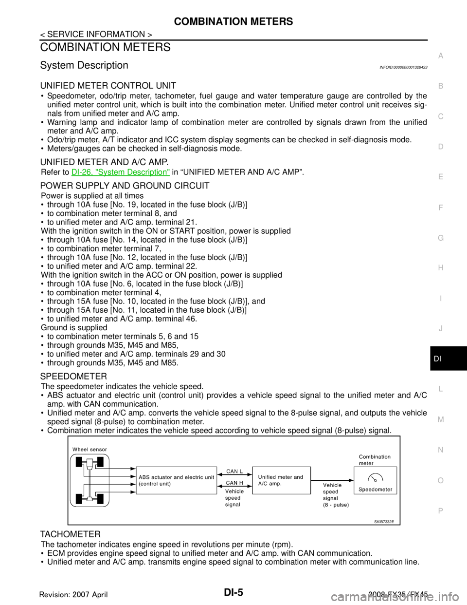
SPEEDOMETER
The speedometer indicates the vehicle speed.
ABS actuator and electric unit (control unit) provides a vehicle speed signal to the unified meter and A/C amp. with CAN communication.
Unified meter and A/C amp. converts the vehicle s peed signal to the 8-pulse signal, and outputs the vehicle
speed signal (8-pulse) to combination meter.
Combination meter indicates the vehicle speed according to vehicle speed signal (8-pulse) signal.
TACHOMETER
The tachometer indicates engine speed in revolutions per minute (rpm).
ECM provides engine speed signal to unified meter and A/C amp. with CAN communication.
Unified meter and A/C amp. transmits engine speed signal to combination meter with communication line.
SKIB7332E
3AA93ABC3ACD3AC03ACA3AC03AC63AC53A913A773A893A873A873A8E3A773A983AC73AC93AC03AC3
3A893A873A873A8F3A773A9D3AAF3A8A3A8C3A863A9D3AAF3A8B3A8C
Page 1155 of 3924
UNIFIED METER AND A/C AMPDI-29
< SERVICE INFORMATION >
C
DE
F
G H
I
J
L
M A
B
DI
N
O P
NOTE:
Monitored item that does not match the vehicle is deleted from the display automatically.
*1: It dose not change when fastening or unfastening the passenger seat belt.
*2: Monitor keeps indicating “off” when brake warning lamp is on by the parking brake operation or low brake fluid level.
Power Supply and Gro und Circuit InspectionINFOID:0000000001328459
1.CHECK FUSE
Check for blown unified meter and A/C amp. fuses.
OK or NG
OK >> GO TO 2.
NG >> Be sure to eliminate cause of malfunction before installing new fuse. Refer to PG-3, "
Schematic".
2.CHECK POWER SUPPLY CIRCUIT
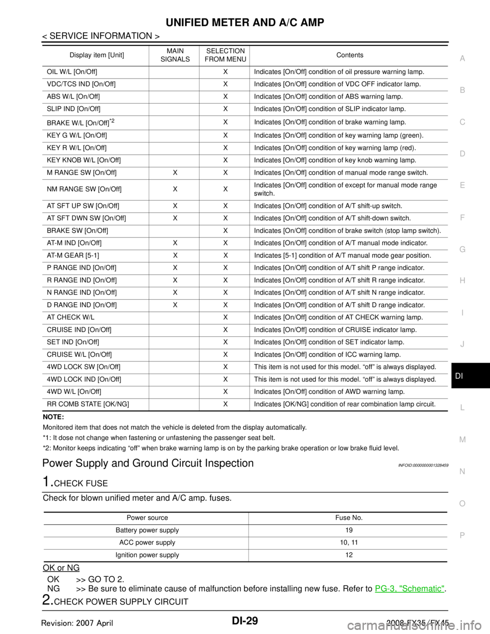
OIL W/L [On/Off] X Indicates [On/Off] condition of oil pressure warning lamp.
VDC/TCS IND [On/Off] X Indicates [On/Off] condition of VDC OFF indicator lamp.
ABS W/L [On/Off] X Indicates [On/Off] condition of ABS warning lamp.
SLIP IND [On/Off] X Indicates [On/Off] condition of SLIP indicator lamp.
BRAKE W/L [On/Off]
*2X Indicates [On/Off] condition of brake warning lamp.
KEY G W/L [On/Off] X Indicates [On/Off] condition of key warning lamp (green).
KEY R W/L [On/Off] X Indicates [On/Off] condition of key warning lamp (red).
KEY KNOB W/L [On/Off] X Indicates [On/Off] condition of key knob warning lamp.
M RANGE SW [On/Off] X X Indicates [On/Off] condition of manual mode range switch.
NM RANGE SW [On/Off] X X Indicates [On/Off] condition of except for manual mode range
switch.
AT SFT UP SW [On/Off] X X Indicates [On/Off] condition of A/T shift-up switch.
AT SFT DWN SW [On/Off] X X Indicates [On/Off] condition of A/T shift-down switch.
BRAKE SW [On/Off] X Indicates [On/Off] condition of brake switch (stop lamp switch).
AT-M IND [On/Off] X X Indicates [On/Off] condition of A/T manual mode indicator.
AT-M GEAR [5-1] X X Indicates [5-1] condition of A/T manual mode gear position.
P RANGE IND [On/Off] X X Indicates [On/Off] condition of A/T shift P range indicator.
R RANGE IND [On/Off] X X Indicates [On/Off] condition of A/T shift R range indicator.
N RANGE IND [On/Off] X X Indicates [On/Off] condition of A/T shift N range indicator.
D RANGE IND [On/Off] X X Indicates [On/Off] condition of A/T shift D range indicator.
AT CHECK W/L X Indicates [On/Off] cond ition of AT CHECK warning lamp.
CRUISE IND [On/Off] X Indicates [On/Off] condition of CRUISE indicator lamp.
SET IND [On/Off] X Indicates [On/Off] condition of SET indicator lamp.
CRUISE W/L [On/Off] X Indicates [On/Of f] condition of ICC warning lamp.
4WD LOCK SW [On/Off] X This item is not used for this model. “off” is always displayed.
4WD LOCK IND [On/Off] X This item is not used for this model. “off” is always displayed.
4WD W/L [On/Off] X Indicates [On/Off] condition of AWD warning lamp.
RR COMB STATE [OK/NG] X Indicates [OK/NG] condition of rear combination lamp circuit. Display item [Unit]
MAIN
SIGNALS SELECTION
FROM MENU Contents
Power source Fuse No.
Battery power supply 19 ACC power supply 10, 11
Ignition power supply 12
3AA93ABC3ACD3AC03ACA3AC03AC63AC53A913A773A893A873A873A8E3A773A983AC73AC93AC03AC3
3A893A873A873A8F3A773A9D3AAF3A8A3A8C3A863A9D3AAF3A8B3A8C
Page 1177 of 3924
WARNING CHIMEDI-51
< SERVICE INFORMATION >
C
DE
F
G H
I
J
L
M A
B
DI
N
O P
WARNING CHIME
System DescriptionINFOID:0000000001328473
Buzzer for warning chime system is installed in the combination meter.
The buzzer sounds when the combination meter receives buzzer output signal from each unit through uni- fied meter and A/C amp.
POWER SUPPLY AND CIRCUIT
Power is supplied at all times
through 50A fusible link (letter M, located in the fuse and fusible link block)
to BCM terminal 55,
through 15A fuse [No. 22, located in the fuse block (J/B)]
to key switch and ignition knob switch terminal 3 (with Intelligent Key), and
to key switch terminal 2 (without Intelligent Key), and
to BCM terminal 42,
through 10A fuse [No. 38, located in the fuse and fusible link block (with Intelligent Key)]
to key switch and ignition knob switch terminal 1,
through 10A fuse [No. 19, located in the fuse block (J/B)]
to unified meter and A/C amp. terminal 21, and
to combination meter terminal 8.
When ignition switch is in ON or START position, power is supplied
through 15A fuse [No. 1, located in the fuse block (J/B)]
to BCM terminal 38,
through 10A fuse [No. 12, located in the fuse block (J/B)]
to unified meter and A/C amp. terminal 22,
through 10A fuse [No. 14, located in the fuse block (J/B)]
to combination meter terminal 7.
Ground is supplied
to BCM terminals 49 and 52,
to unified meter and A/C amp. terminals 29 and 30, and
to combination meter terminals 5, 6 and 15
through grounds M35, M45 and M85.
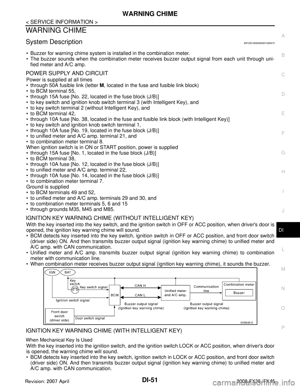
IGNITION KEY WARNING CHIME (WITHOUT INTELLIGENT KEY)
With the key inserted into the key switch, and the igniti on switch in OFF or ACC position, when driver's door is
opened, the ignition key warning chime will sound.
BCM detects key inserted into the key switch, igniti on switch in OFF or ACC position, and front door switch
(driver side) ON. And then transmits buzzer output signal (ignition key warning chime) to unified meter and
A/C amp. with CAN communication.
Unified meter and A/C amp. transmits buzzer output signal (ignition key warning chime) to combination
meter with communication line.
When combination meter receives buzzer output signal (ignition key warning chime), it sounds the buzzer.
IGNITION KEY WARNING CHIME (WITH INTELLIGENT KEY)
When Mechanical Key Is Used
With the key inserted into the ignition switch, and the i gnition switch LOCK or ACC position, when driver's door
is opened, the warning chime will sound.
BCM detects key inserted into the key switch, ignition switch in LOCK or ACC position, and front door switch
(driver side) ON. And then transmits buzzer output signal (ignition key warning chime) to unified meter and
A/C amp. with CAN communication.
SKIB6481E
3AA93ABC3ACD3AC03ACA3AC03AC63AC53A913A773A893A873A873A8E3A773A983AC73AC93AC03AC3
3A893A873A873A8F3A773A9D3AAF3A8A3A8C3A863A9D3AAF3A8B3A8C
Page 1178 of 3924
DI-52
< SERVICE INFORMATION >
WARNING CHIME
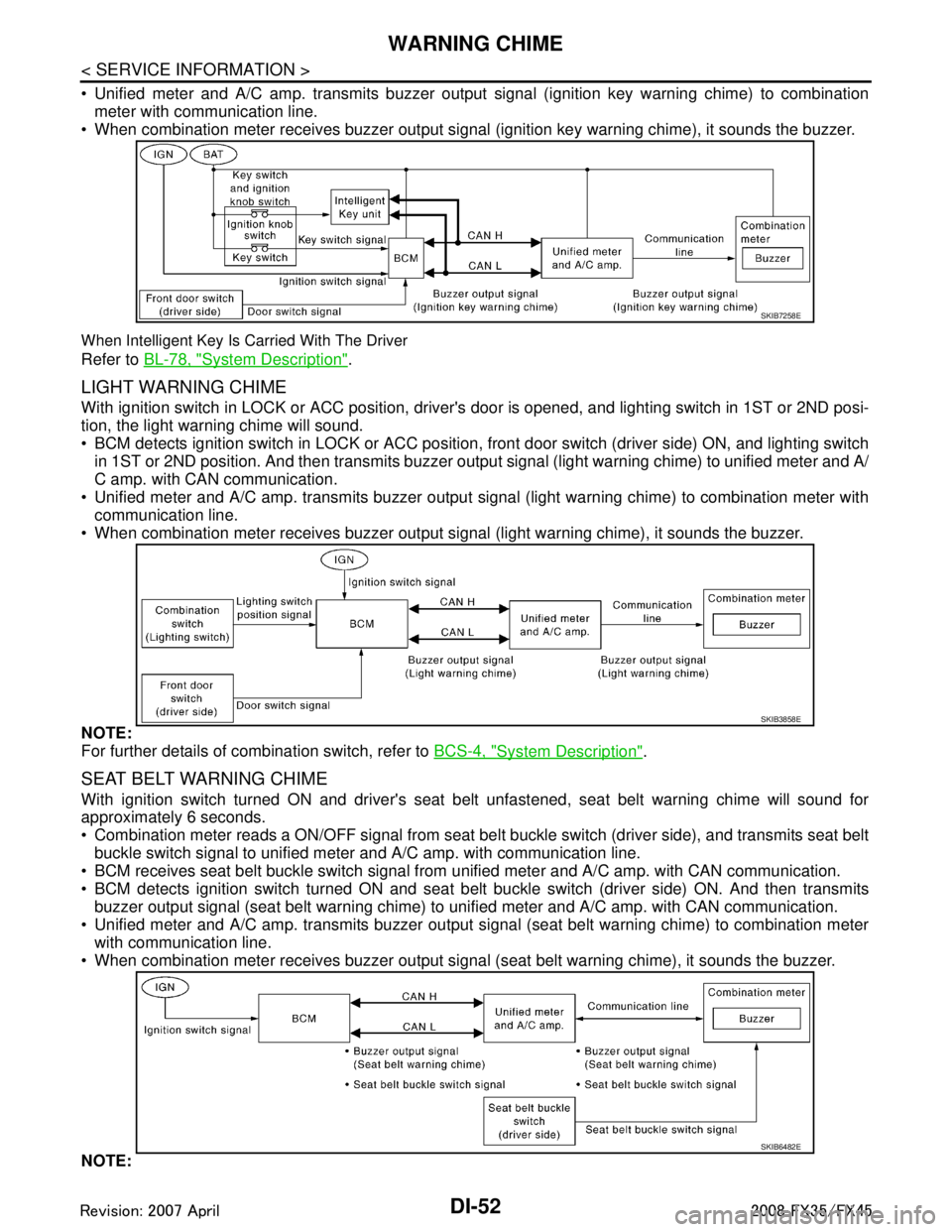
Unified meter and A/C amp. transmits buzzer output signal (ignition key warning chime) to combinationmeter with communication line.
When combination meter receives buzzer output signal (ignition key warning chime), it sounds the buzzer.
When Intelligent Key Is Carried With The Driver
Refer to BL-78, "System Description".
LIGHT WARNING CHIME
With ignition switch in LOCK or ACC position, driver 's door is opened, and lighting switch in 1ST or 2ND posi-
tion, the light warning chime will sound.
BCM detects ignition switch in LOCK or ACC position, front door switch (driver side) ON, and lighting switch
in 1ST or 2ND position. And then transmits buzzer output signal (light warning chime) to unified meter and A/
C amp. with CAN communication.
Unified meter and A/C amp. transmits buzzer output signal (light warning chime) to combination meter with
communication line.
When combination meter receives buzzer output signal (light warning chime), it sounds the buzzer.
NOTE:
For further details of combination switch, refer to BCS-4, "
System Description".
SEAT BELT WARNING CHIME
With ignition switch turned ON and driver's seat belt unfastened, seat belt warning chime will sound for
approximately 6 seconds.
Combination meter reads a ON/OFF signal from seat bel t buckle switch (driver side), and transmits seat belt
buckle switch signal to unified meter and A/C amp. with communication line.
BCM receives seat belt buckle switch signal from unified meter and A/C amp. with CAN communication.
BCM detects ignition switch turned ON and seat bel t buckle switch (driver side) ON. And then transmits
buzzer output signal (seat belt warning chime) to unified meter and A/C amp. with CAN communication.
Unified meter and A/C amp. transmits buzzer output signal (seat belt warning chime) to combination meter with communication line.
When combination meter receives buzzer output signal (seat belt warning chime), it sounds the buzzer.
NOTE:
SKIB7258E
SKIB3858E
SKIB6482E
3AA93ABC3ACD3AC03ACA3AC03AC63AC53A913A773A893A873A873A8E3A773A983AC73AC93AC03AC3
3A893A873A873A8F3A773A9D3AAF3A8A3A8C3A863A9D3AAF3A8B3A8C
Page 1197 of 3924
LANE DEPARTURE WARNING SYSTEMDI-71
< SERVICE INFORMATION >
C
DE
F
G H
I
J
L
M A
B
DI
N
O P
NOTE:
*: This indicates in a few seconds for the system check during ignition switch ON.
POWER SUPPLY AND GROUND CIRCUIT
With the ignition switch in the ON or START position, power is supplied
through 10A fuse [No. 12, located in the fuse block (J/B)]
to LDW camera unit terminal 1.
Ground is supplied
to LDW camera unit terminals 6 and 12
through grounds M45, M85 and M35.
Action TestINFOID:0000000001328494
LDW SYSTEM RUNNING TEST
WARNING:
Be careful when performing road test.
Understand “Precautions” and “System Description” well before the road test. Refer to DI-69, "
Pre-
caution for Lane Departure Warning (LDW) system" and DI-69, "System Description".
Function Check
Check the LDW system operation according to the c ondition that the warning function works. Refer to DI-69,
"System Description".
Camera Aiming AdjustmentINFOID:0000000001328495
OUTLINE
Adjust the camera aiming every time the LDW camera unit is removed or installed.
CAUTION:
Place the vehicle on the level ground when the camera aiming adjustment is operated.
Follow the CONSULT-III when ad justing the camera aiming. (Camera aiming adjustment cannot be
operated without CONSULT-III.)
PREPARATION
Keep all tires inflated to correct pressures. Adjust the tire pressure to the specified pressure value.
There is no-load in vehicle. Check if coolant, engine oil are filled up to correct level and fuel tank is full.
Shift the gear into “P” position and release the parking brake.
Clean the windshield.
NOTE:
Do not place anything reflective on t he upper surface of instrument panel.
TARGET SETTING
Preparation Aiming Adjustment Jig
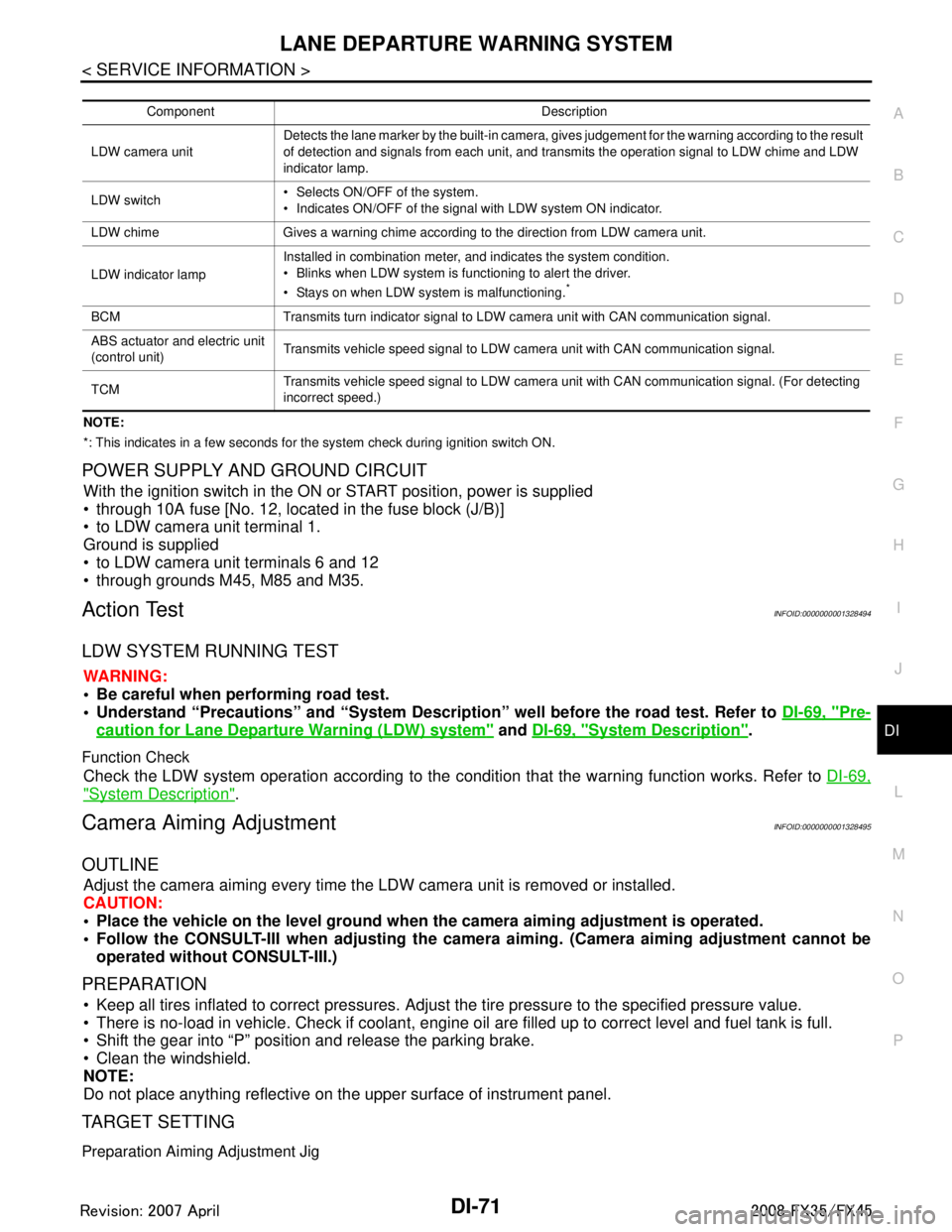
Component Description
LDW camera unit Detects the lane marker by the built-in camera, gives judgement for the warning according to the result
of detection and signals from each unit, and transmits the operation signal to LDW chime and LDW
indicator lamp.
LDW switch Selects ON/OFF of the system.
Indicates ON/OFF of the signal with LDW system ON indicator.
LDW chime Gives a warning chime according to the direction from LDW camera unit.
LDW indicator lamp Installed in combination meter, and indicates the system condition.
Blinks when LDW system is functioning to alert the driver.
Stays on when LDW system is malfunctioning.
*
BCM Transmits turn indicator signal to LDW camera unit with CAN communication signal.
ABS actuator and electric unit
(control unit)
Transmits vehicle speed signal to LDW camera unit with CAN communication signal.
TCM Transmits vehicle speed signal to LDW camera unit with CAN communication signal. (For detecting
incorrect speed.)
3AA93ABC3ACD3AC03ACA3AC03AC63AC53A913A773A893A873A873A8E3A773A983AC73AC93AC03AC3
3A893A873A873A8F3A773A9D3AAF3A8A3A8C3A863A9D3AAF3A8B3A8C
Page 1221 of 3924
COMPASSDI-95
< SERVICE INFORMATION >
C
DE
F
G H
I
J
L
M A
B
DI
N
O P
During normal operation, the Compass Mirror will cont inuously update the compass calibration to adjust for
gradual changes in the vehicle's magnetic “remnant” field. If the vehicle is subjected to high magnetic influ-
ences, the compass may appear to indicate false headings , become locked, or appear that it is unable to be
calibrated. If this occurs, perform the calibration procedure.
If at any time the compass continually displays the inco rrect direction or the reading is erratic or locked, ver-
ify the correct zone variance.
Troubleshooting Chart
Zone Variation Setting ProcedureINFOID:0000000001328523
NOTE:
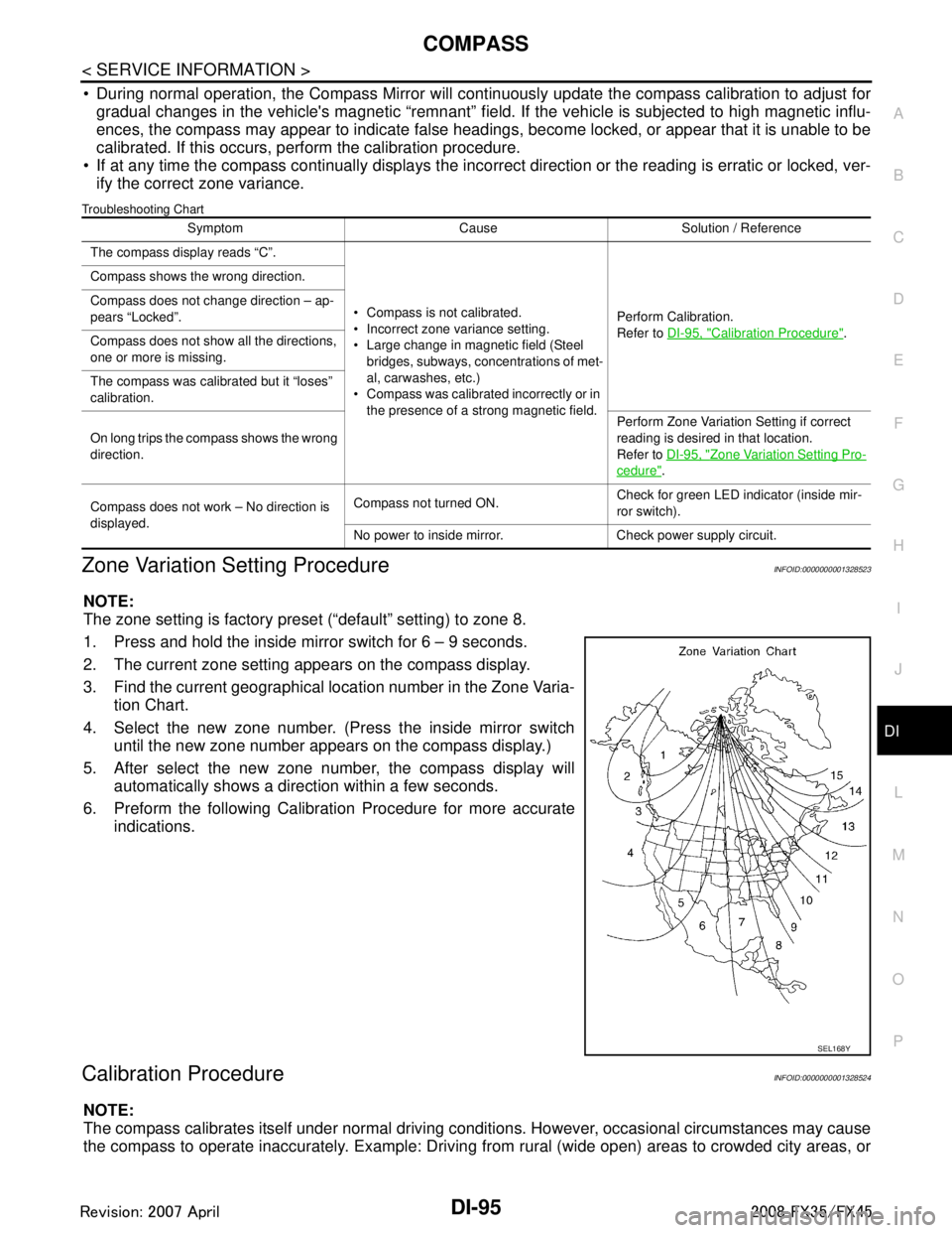
The zone setting is factory preset (“default” setting) to zone 8.
1. Press and hold the inside mirror switch for 6 – 9 seconds.
2. The current zone setting appears on the compass display.
3. Find the current geographical location number in the Zone Varia-
tion Chart.
4. Select the new zone number. (Press the inside mirror switch until the new zone number appears on the compass display.)
5. After select the new zone number, the compass display will automatically shows a direction within a few seconds.
6. Preform the following Calibration Procedure for more accurate indications.
Calibration ProcedureINFOID:0000000001328524
NOTE:
The compass calibrates itself under normal driving conditions. However, occasional circumstances may cause
the compass to operate inaccurately. Example: Driving from rural (wide open) areas to crowded city areas, or
Symptom Cause Solution / Reference
The compass display reads “C”.
Compass is not calibrated.
Incorrect zone variance setting.
Large change in magnetic field (Steel bridges, subways, concentrations of met-
al, carwashes, etc.)
Compass was calibrated incorrectly or in
the presence of a strong magnetic field. Perform Calibration.
Refer to
DI-95, "
Calibration Procedure".
Compass shows the wrong direction.
Compass does not change direction – ap-
pears “Locked”.
Compass does not show all the directions,
one or more is missing.
The compass was calibrated but it “loses”
calibration.
On long trips the compass shows the wrong
direction.
Perform Zone Variatio
n Setting if correct
reading is desired in that location.
Refer to DI-95, "
Zone Variation Setting Pro-
cedure".
Compass does not work – No direction is
displayed. Compass not turned ON.
Check for green LED indicator (inside mir-
ror switch).
No power to inside mirror. Check power supply circuit.
SEL168Y
3AA93ABC3ACD3AC03ACA3AC03AC63AC53A913A773A893A873A873A8E3A773A983AC73AC93AC03AC3
3A893A873A873A8F3A773A9D3AAF3A8A3A8C3A863A9D3AAF3A8B3A8C