2008 INFINITI FX35 oil capacity
[x] Cancel search: oil capacityPage 3340 of 3924
ENGINE MAINTENANCE (VK45DE ENGINE)MA-23
< SERVICE INFORMATION >
C
DE
F
G H
I
J
K
M A
B
MA
N
O P
The refill capacity depends on the engine oi l temperature and drain time. Use these specifica-
tions for reference only.
Always use oil level gauge to determine the pr oper amount of engine oil in the engine.
8. Warm up engine and check area around drain plug and oil filter for oil leakage.
9. Stop engine and wait for 15 minutes.
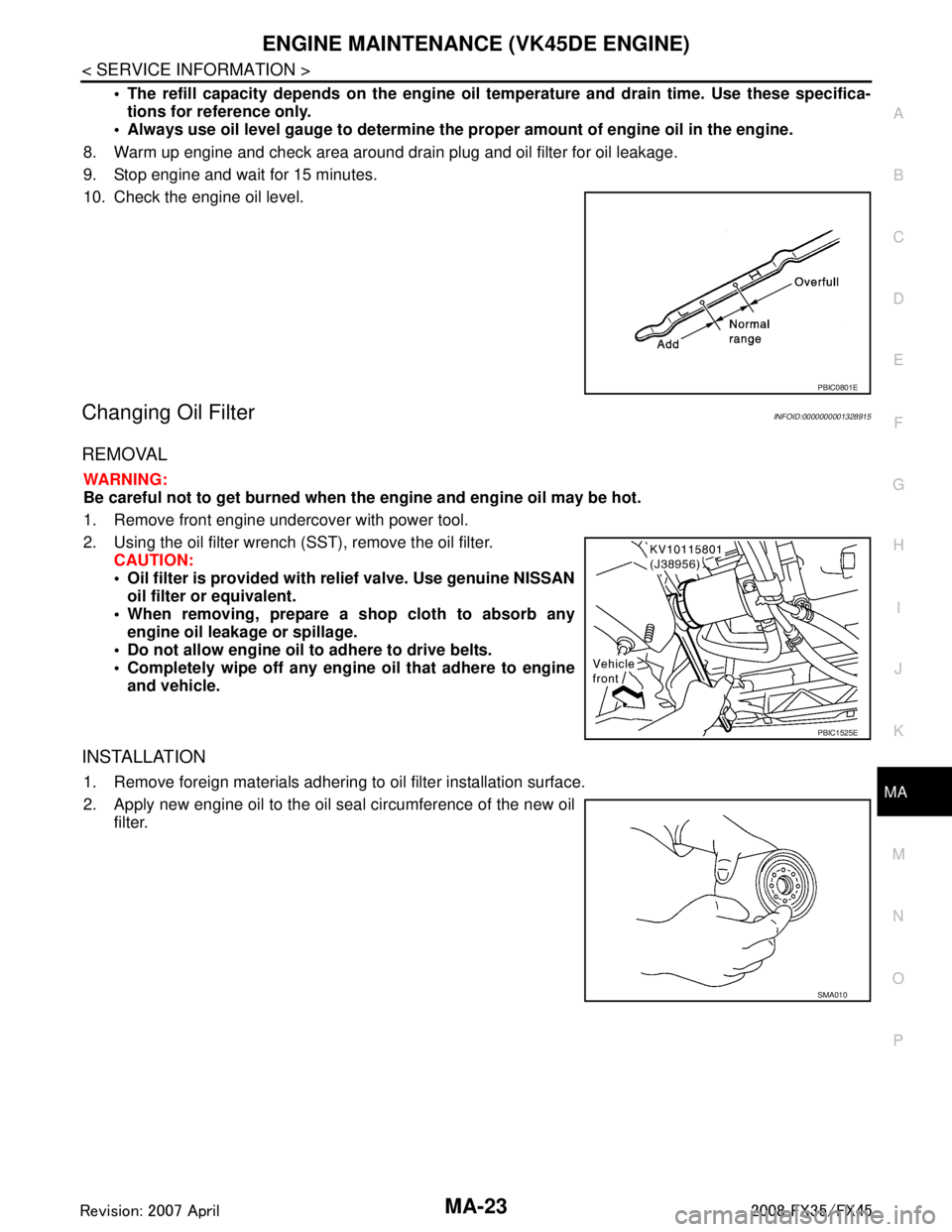
10. Check the engine oil level.
Changing Oil FilterINFOID:0000000001328915
REMOVAL
WARNING:
Be careful not to get burned when th e engine and engine oil may be hot.
1. Remove front engine undercover with power tool.
2. Using the oil filter wrench (SST), remove the oil filter. CAUTION:
Oil filter is provided with relief valve. Use genuine NISSAN
oil filter or equivalent.
When removing, prepare a s hop cloth to absorb any
engine oil leakage or spillage.
Do not allow engine oil to adhere to drive belts.
Completely wipe off any engine oil that adhere to engine
and vehicle.
INSTALLATION
1. Remove foreign materials adhering to oil filter installation surface.
2. Apply new engine oil to the oil seal circumference of the new oil filter.
PBIC0801E
PBIC1525E
SMA010
3AA93ABC3ACD3AC03ACA3AC03AC63AC53A913A773A893A873A873A8E3A773A983AC73AC93AC03AC3
3A893A873A873A8F3A773A9D3AAF3A8A3A8C3A863A9D3AAF3A8B3A8C
Page 3346 of 3924
CHASSIS AND BODY MAINTENANCEMA-29
< SERVICE INFORMATION >
C
DE
F
G H
I
J
K
M A
B
MA
N
O P
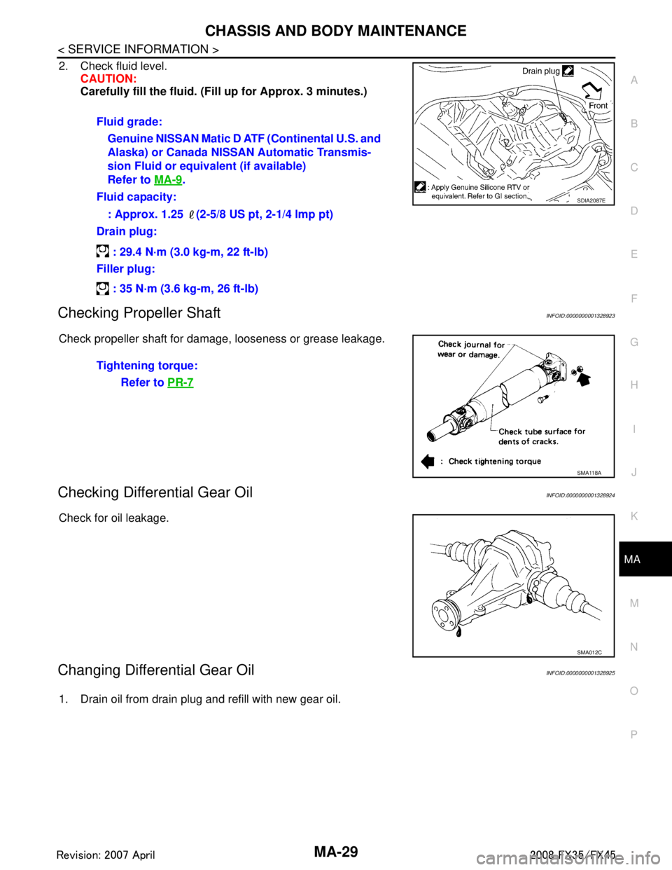
2. Check fluid level. CAUTION:
Carefully fill the fluid. (Fil l up for Approx. 3 minutes.)
Checking Propeller ShaftINFOID:0000000001328923
Check propeller shaft for damage, looseness or grease leakage.
Checking Differential Gear OilINFOID:0000000001328924
Check for oil leakage.
Changing Differential Gear OilINFOID:0000000001328925
1. Drain oil from drain plug and refill with new gear oil.Fluid grade:
Genuine NISSAN Matic D ATF (Continental U.S. and
Alaska) or Canada NISSAN Automatic Transmis-
sion Fluid or equivalent (if available)
Refer to MA-9
.
Fluid capacity:
: Approx. 1.25 (2-5/8 US pt, 2-1/4 lmp pt)
Drain plug:
: 29.4 N·m (3.0 kg-m, 22 ft-lb)
Filler plug:
: 35 N·m (3.6 kg-m, 26 ft-lb)
SDIA2087E
Tightening torque: Refer to PR-7
SMA118A
SMA012C
3AA93ABC3ACD3AC03ACA3AC03AC63AC53A913A773A893A873A873A8E3A773A983AC73AC93AC03AC3
3A893A873A873A8F3A773A9D3AAF3A8A3A8C3A863A9D3AAF3A8B3A8C
Page 3347 of 3924
MA-30
< SERVICE INFORMATION >
CHASSIS AND BODY MAINTENANCE
2. Check oil level.
Balancing Wheels (Bonding Weight Type)INFOID:0000000001328926
REMOVAL
Using releasing agent, remove double-faced adhesive tape from the road wheel.
CAUTION:
Be careful not to scratch th e road wheel during removal.
After removing double-faced adhesive tape, wi pe clean traces of releasing agent from the road
wheel.
WHEEL BALANCE ADJUSTMENT
If a tire balance machine has adhesion balance weight mode settings and drive-in weight mode setting,
select and adjust a drive-in weight mode suitable for road wheels.
1. Set road wheel on tire balance machine using the center hole as a guide. Start the tire balance machine.
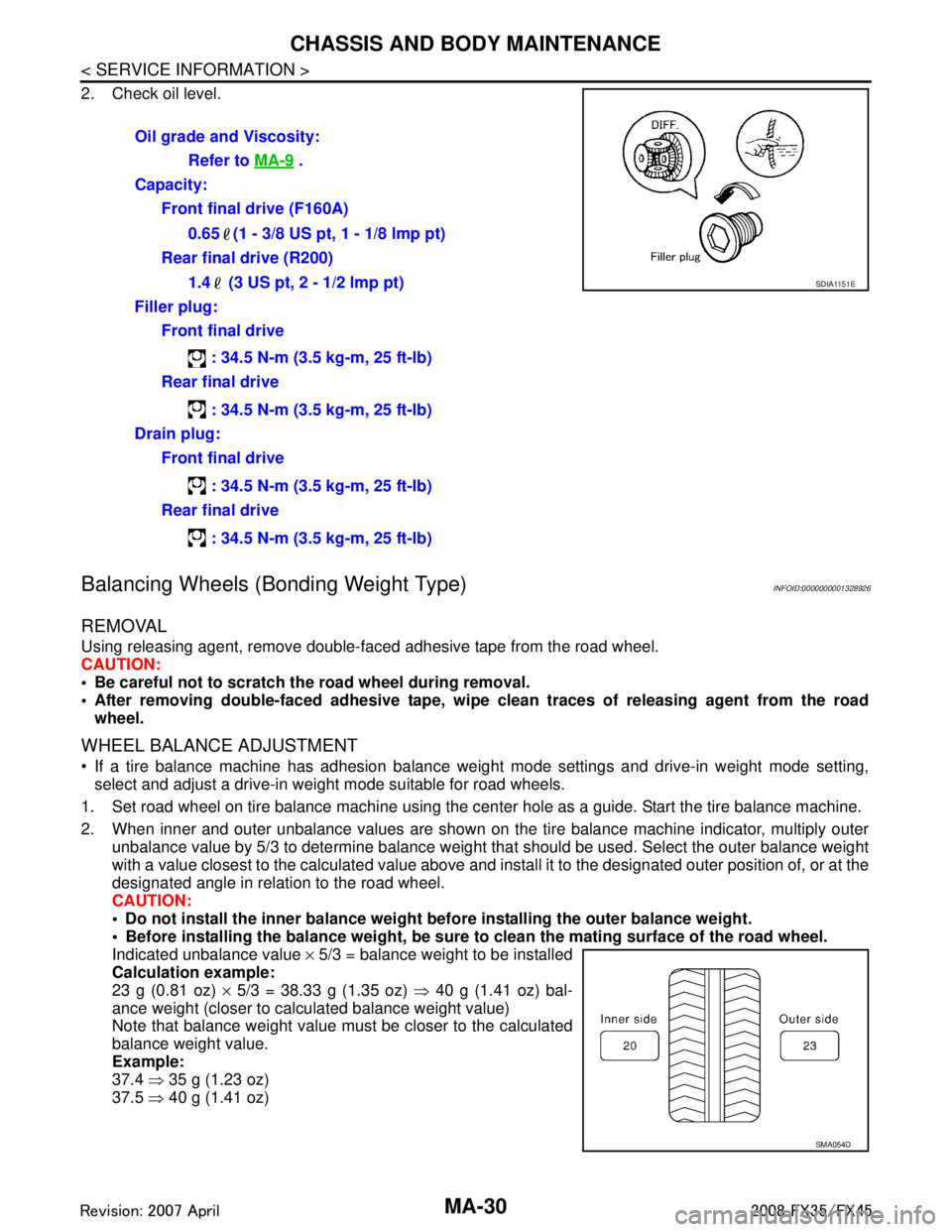
2. When inner and outer unbalance values are shown on the tire balance machine indicator, multiply outer unbalance value by 5/3 to determine balance weight t hat should be used. Select the outer balance weight
with a value closest to the calculated value above and inst all it to the designated outer position of, or at the
designated angle in relation to the road wheel.
CAUTION:
Do not install the inner balance weight before installing the outer balance weight.
Before installing the balance weight, be sure to clean the mating surface of the road wheel.
Indicated unbalance value × 5/3 = balance weight to be installed
Calculation example:
23 g (0.81 oz) × 5/3 = 38.33 g (1.35 oz) ⇒ 40 g (1.41 oz) bal-
ance weight (closer to calculated balance weight value)
Note that balance weight value must be closer to the calculated
balance weight value.
Example:
37.4 ⇒ 35 g (1.23 oz)
37.5 ⇒ 40 g (1.41 oz)
Oil grade and Viscosity:
Refer to MA-9
.
Capacity: Front final drive (F160A)
0.65 (1 - 3/8 US pt, 1 - 1/8 lmp pt)
Rear final drive (R200)
1.4 (3 US pt, 2 - 1/2 lmp pt)
Filler plug: Front final drive
: 34.5 N-m (3.5 kg-m, 25 ft-lb)
Rear final drive
: 34.5 N-m (3.5 kg-m, 25 ft-lb)
Drain plug: Front final drive
: 34.5 N-m (3.5 kg-m, 25 ft-lb)
Rear final drive
: 34.5 N-m (3.5 kg-m, 25 ft-lb)
SDIA1151E
SMA054D
:
Page 3354 of 3924
SERVICE DATA AND SPECIFICATIONS (SDS)
MA-37
< SERVICE INFORMATION >
C
D E
F
G H
I
J
K
M A
B
MA
N
O P
SERVICE DATA AND SPECIFICATIONS (SDS)
Standard and LimitINFOID:0000000001328938
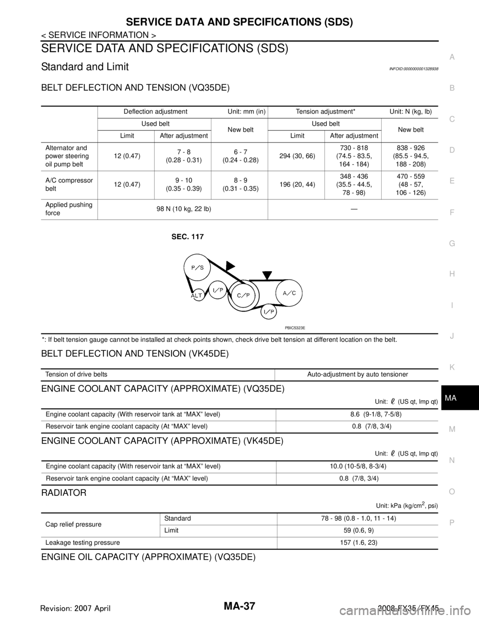
BELT DEFLECTION AND TENSION (VQ35DE)
*: If belt tension gauge cannot be installed at check points shown, check drive belt tension at different location on the belt.
BELT DEFLECTION AND TENSION (VK45DE)
ENGINE COOLANT CAPACITY (APPROXIMATE) (VQ35DE)
Unit: (US qt, lmp qt)
ENGINE COOLANT CAPACITY (APPROXIMATE) (VK45DE)
Unit: (US qt, lmp qt)
RADIATOR
Unit: kPa (kg/cm2, psi)
ENGINE OIL CAPACITY (APPROXIMATE) (VQ35DE)
Deflection adjustment Unit: mm (in) Tension adjustment* Unit: N (kg, lb) Used belt New beltUsed belt
New belt
Limit After adjustment Limit After adjustment
Alternator and
power steering
oil pump belt 12 (0.47)
7 - 8
(0.28 - 0.31) 6 - 7
(0.24 - 0.28) 294 (30, 66) 730 - 818
(74.5 - 83.5, 164 - 184) 838 - 926
(85.5 - 94.5, 188 - 208)
A/C compressor
belt 12 (0.47)
9 - 10
(0.35 - 0.39) 8 - 9
(0.31 - 0.35) 196 (20, 44) 348 - 436
(35.5 - 44.5,
78 - 98) 470 - 559
(48 - 57,
106 - 126)
Applied pushing
force 98 N (10 kg, 22 lb) —
PBIC5323E
Tension of drive belts Auto-adjustment by auto tensioner
Engine coolant capacity (With reservoir tank at “MAX” level) 8.6 (9-1/8, 7-5/8)
Reservoir tank engine coolant capacity (At “MAX” level) 0.8 (7/8, 3/4)
Engine coolant capacity (With reservoir tank at “MAX” level) 10.0 (10-5/8, 8-3/4)
Reservoir tank engine coolant capacity (At “MAX” level) 0.8 (7/8, 3/4)
Cap relief pressure Standard 78 - 98 (0.8 - 1.0, 11 - 14)
Limit 59 (0.6, 9)
Leakage testing pressure 157 (1.6, 23)
3AA93ABC3ACD3AC03ACA3AC03AC63AC53A913A773A893A873A873A8E3A773A983AC73AC93AC03AC3
3A893A873A873A8F3A773A9D3AAF3A8A3A8C3A863A9D3AAF3A8B3A8C
Page 3355 of 3924

MA-38
< SERVICE INFORMATION >
SERVICE DATA AND SPECIFICATIONS (SDS)
Unit: (US qt, lmp qt)
ENGINE OIL CAPACITY (APPROXIMATE) (VK45DE)
Unit: (US qt, lmp qt)
SPARK PLUG (PLATINUM-TIPPED TYPE) (VQ35DE)
SPARK PLUG (PLATINUM-TIPPED TYPE) (VK45DE)
WHEEL BALANCE
Drain and refill With oil filter change 4.7 (5, 4-1/8)
Without oil filter change 4.4 (4-5/8, 3-7/8)
Dry engine (Overhaul) 5.4 (5-3/4, 4-3/4)
Drain and refillWith oil filter change 5.8 (6-1/8, 5-1/8)
Without oil filter change 5.2 (5-1/2, 4-5/8)
Dry engine (Overhaul) 7.0 (7-3/8, 6-1/8)
Make NGK
Ty p e Standard PLFR5A-11
Hot PLFR4A-11
Cold PLFR6A-11
Gap (Nominal) 1.1mm (0.043 in)
Make NGK
Typ e Standard PLFR5A-11
Hot PLFR4A-11
Cold PLFR6A-11
Gap (Nominal) 1.1mm (0.043 in)
Maximum allowable unbalanceDynamic (At rim flange) Less than 5.0 g (0.18 oz) (one side)
Static (At rim flange) Less than 20 g (0.71 oz)
3AA93ABC3ACD3AC03ACA3AC03AC63AC53A913A773A893A873A873A8E3A773A983AC73AC93AC03AC3
3A893A873A873A8F3A773A9D3AAF3A8A3A8C3A863A9D3AAF3A8B3A8C
Page 3498 of 3924
SERVICE DATA AND SPECIFICATIONS (SDS)
PS-43
< SERVICE INFORMATION >
C
D E
F
H I
J
K L
M A
B
PS
N
O P
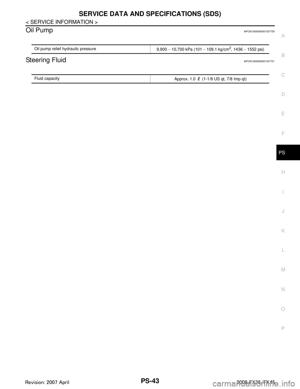
Oil PumpINFOID:0000000001327730
Steering FluidINFOID:0000000001327731
Oil pump relief hydraulic pressure 9,900 − 10,700 kPa (101 − 109.1 kg/cm2, 1436 − 1552 psi)
Fluid capacity
Approx. 1.0 (1-1/8 US qt, 7/8 Imp qt)
3AA93ABC3ACD3AC03ACA3AC03AC63AC53A913A773A893A873A873A8E3A773A983AC73AC93AC03AC3
3A893A873A873A8F3A773A9D3AAF3A8A3A8C3A863A9D3AAF3A8B3A8C
Page 3551 of 3924
DIFFERENTIAL GEAR OILRFD-9
< SERVICE INFORMATION >
CEF
G H
I
J
K L
M A
B
RFD
N
O P
DIFFERENTIAL GEAR OIL
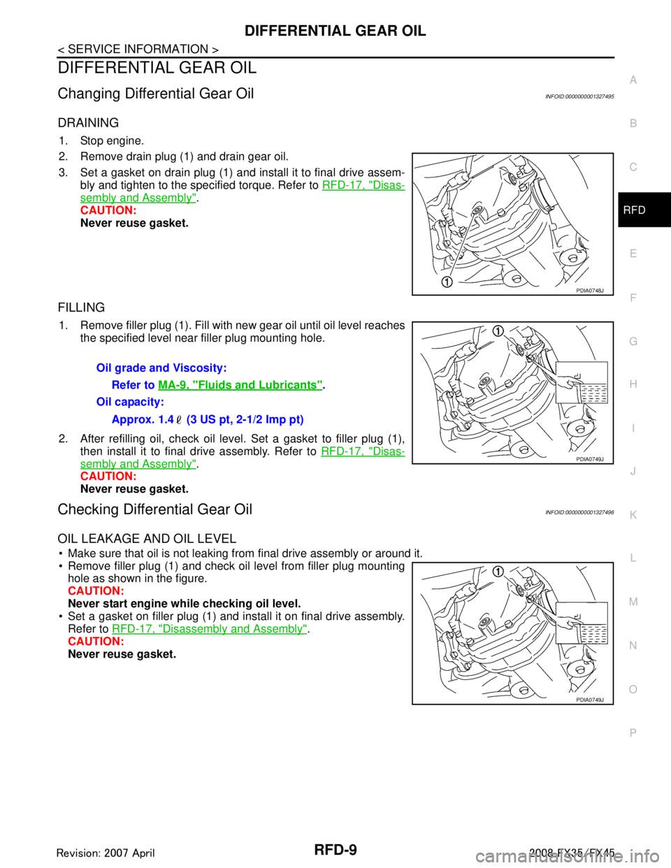
Changing Differential Gear OilINFOID:0000000001327495
DRAINING
1. Stop engine.
2. Remove drain plug (1) and drain gear oil.
3. Set a gasket on drain plug (1) and install it to final drive assem- bly and tighten to the specified torque. Refer to RFD-17, "
Disas-
sembly and Assembly".
CAUTION:
Never reuse gasket.
FILLING
1. Remove filler plug (1). Fill with new gear oil until oil level reaches the specified level near filler plug mounting hole.
2. After refilling oil, check oil level. Set a gasket to filler plug (1), then install it to final drive assembly. Refer to RFD-17, "
Disas-
sembly and Assembly".
CAUTION:
Never reuse gasket.
Checking Differential Gear OilINFOID:0000000001327496
OIL LEAKAGE AND OIL LEVEL
Make sure that oil is not leaking from final drive assembly or around it.
Remove filler plug (1) and check oil level from filler plug mounting hole as shown in the figure.
CAUTION:
Never start engine while checking oil level.
Set a gasket on filler plug (1) and install it on final drive assembly.
Refer to RFD-17, "
Disassembly and Assembly".
CAUTION:
Never reuse gasket.
PDIA0748J
Oil grade and Viscosity:
Refer to MA-9, "
Fluids and Lubricants".
Oil capacity:
Approx. 1.4 (3 US pt, 2-1/2 Imp pt)
PDIA0749J
PDIA0749J
3AA93ABC3ACD3AC03ACA3AC03AC63AC53A913A773A893A873A873A8E3A773A983AC73AC93AC03AC3
3A893A873A873A8F3A773A9D3AAF3A8A3A8C3A863A9D3AAF3A8B3A8C
Page 3580 of 3924
RFD-38
< SERVICE INFORMATION >
SERVICE DATA AND SPECIFICATIONS (SDS)
SERVICE DATA AND SPECIFICATIONS (SDS)
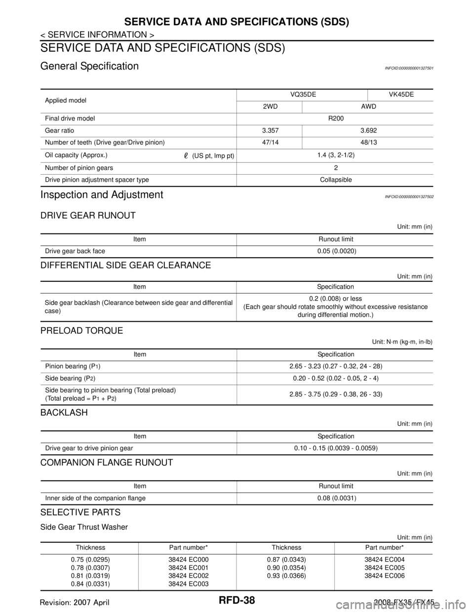
General SpecificationINFOID:0000000001327501
Inspection and AdjustmentINFOID:0000000001327502
DRIVE GEAR RUNOUT
Unit: mm (in)
DIFFERENTIAL SIDE GEAR CLEARANCE
Unit: mm (in)
PRELOAD TORQUE
Unit: N·m (kg-m, in-lb)
BACKLASH
Unit: mm (in)
COMPANION FLANGE RUNOUT
Unit: mm (in)
SELECTIVE PARTS
Side Gear Thrust Washer
Unit: mm (in)
Applied modelVQ35DE VK45DE
2WD AWD
Final drive model R200
Gear ratio 3.357 3.692
Number of teeth (Drive gear/Drive pinion) 47/14 48/13
Oil capacity (Approx.) (US pt, lmp pt)1.4 (3, 2-1/2)
Number of pinion gears 2
Drive pinion adjustment spacer type Collapsible
Item Runout limit
Drive gear back face 0.05 (0.0020)
Item Specification
Side gear backlash (Clearance between side gear and differential
case) 0.2 (0.008) or less
(Each gear should rotate smoothly without excessive resistance
during differential motion.)
Item Specification
Pinion bearing (P
1) 2.65 - 3.23 (0.27 - 0.32, 24 - 28)
Side bearing (P
2) 0.20 - 0.52 (0.02 - 0.05, 2 - 4)
Side bearing to pinion bearing (Total preload)
(Total preload = P
1 + P2) 2.85 - 3.75 (0.29 - 0.38, 26 - 33)
Item Specification
Drive gear to drive pinion gear 0.10 - 0.15 (0.0039 - 0.0059)
Item Runout limit
Inner side of the companion flange 0.08 (0.0031)
Thickness Part number* Thickness Part number*
0.75 (0.0295)
0.78 (0.0307)
0.81 (0.0319)
0.84 (0.0331) 38424 EC000
38424 EC001
38424 EC002
38424 EC003 0.87 (0.0343)
0.90 (0.0354)
0.93 (0.0366)
38424 EC004
38424 EC005
38424 EC006
3AA93ABC3ACD3AC03ACA3AC03AC63AC53A913A773A893A873A873A8E3A773A983AC73AC93AC03AC3
3A893A873A873A8F3A773A9D3AAF3A8A3A8C3A863A9D3AAF3A8B3A8C